WARNING
The
following
instructions
are
for
use
by
qualified
personnel
only.
To
avoid
electric
shock,
do
not
per-
form
servicing
other
than
contained
in
the
operating
instructions
unless
you
are
qualified
to
do
so.
SAFETY
Before
connecting
the
instrument
to
a
power
source,
carefully
read
the
following
information,
then
verify
that
the
proper
power
cord
is
used
and
the
proper
line
fuse
is
in-
stalled
for
power
source.
If
the
power
cord
is
not
applied
for
specified
voltage,
there
is
always
a
certain
amount
of
danger
from
electric
shock.
Line
voltage
This
instrument
operates
using
ac-power
input
voltages
that
100/120/220/240
V
at
frequencies
from
50 Hz
to
60
Hz.
Power
cord
The
ground
wire
of
the
3-wire
ac
power
plug
places
the
chassis
and
housing
of
this
instrument
at
earth
ground.
Do
not
attempt
to
defeat
the
ground
wire
connection
or
float
this
instrument;
to
do
so
may
pose
a
great
safety
hazard.
The
appropriate
power
cord
is
supplied
by
an
option
that
is
specified
when
the
instrument
is
ordered.
Waming
If
groundings,
especially
points
|
(Vg)
and
¥
(Ig),
are
short-
circuited
during
servicing,
it
could
lead
to
pattern
damage
due
to
large
amount
of
current
flow
on
the
PCB.
Take
ap-
propriate
care.
CONTENTS
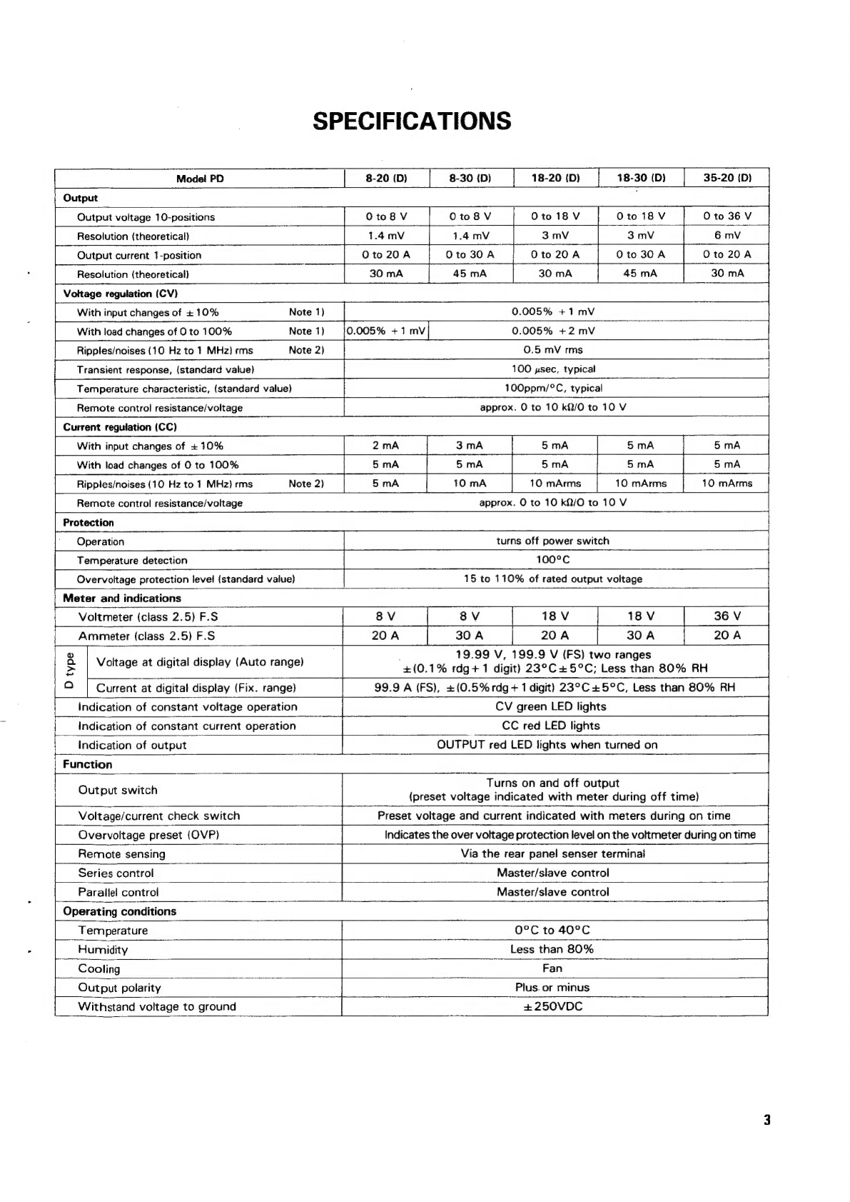
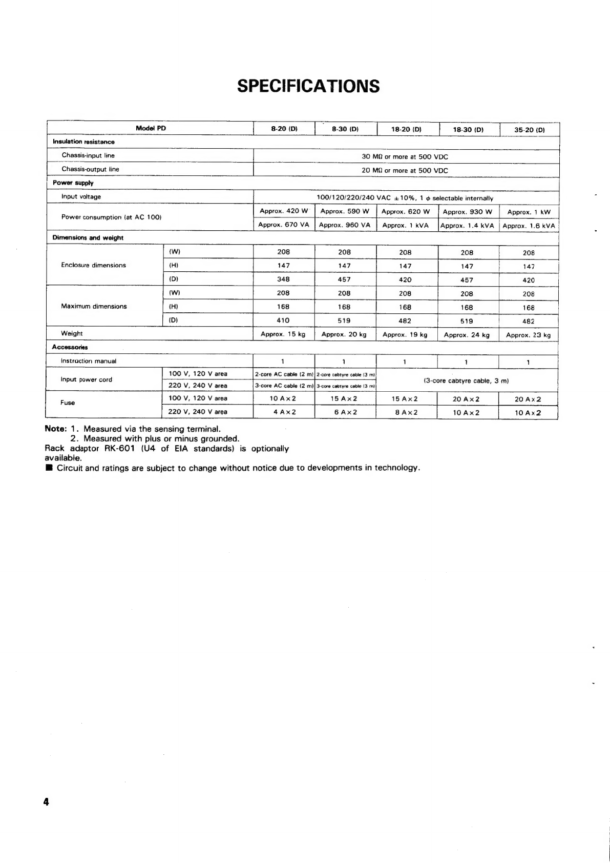
SPECIFICATIONS.
.............ccceeesceseneeeeseneenes
DISASSEMBLY
............:02cceceeeeceeseneeceneees
BLOCK
DIAGRAM
.............2:::ecceeseeesereeeeeee
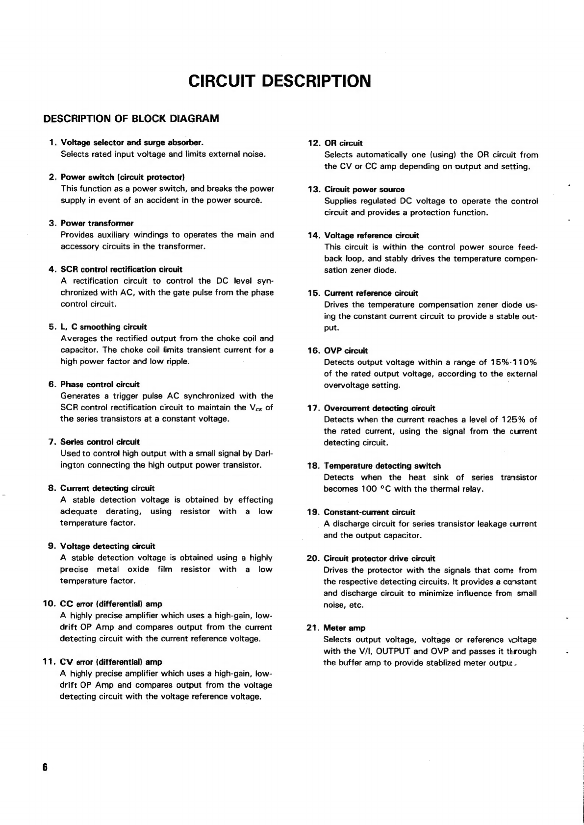
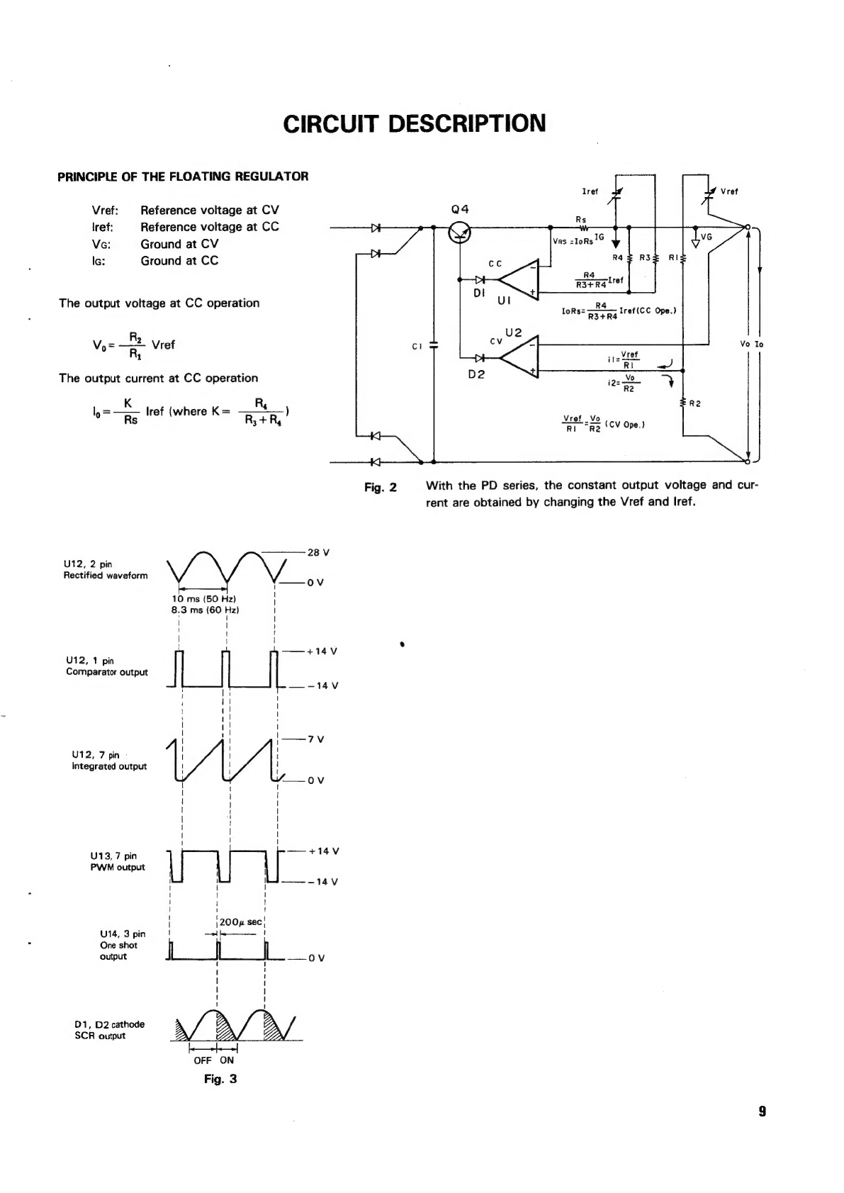
CIRCUIT
DESCRIPTION
............0ccseceseeeeseees
ADJUSTMENT.........c0:ecseseereccecsvcersrseeseeees
TROUBLESHOOTING.
..........:ccccesceeceetsereeeees
PARTS
LIST
..........
ce
ceceseeceeeeeeeceerseneenennees
SCHEMATIC
DIAGRAM.
............000.eeseceeeees
P.C.
BOARD
.........ce
cece
eccceeeeteeeenneceneeneeecens
DISASSEMBLY
............2:0ccsseseeceeseceeeeeeeees
SEMICONDUCTORS
............::cccseseceeseeeeeees