Caen A1539 User manual

CAEN
Tools for Discovery
n
Electronic Instrumentation
Rev. 0 -
Es
A1539, AG539, A154X, AG54X Power Supply
Boards
Rev. 2 - 6 May 2015

Purpose of this Manual
This document is the A1539, AG539, A154X, AG54X Power Supply Boards manual; it contains information about the
installation, the configuration and the use of the board.
Change Document Record
Date
Revision
Changes
25 November 2013
0
PRELIMINARY Release
5 December 2014
1
Updated with dual range versions
6 May 2015
2
Updated Technical specifications
Symbols, abbreviated terms and notation
T.B.D.
Reference Documents
Disclaimer
No part of this manual may be reproduced in any form or by any means, electronic, mechanical, recording, or
otherwise, without the prior written permission of CAEN SpA.
CAEN will repair or replace any product within the guarantee period if the Guarantor declares that the product is
defective due to workmanship or materials and has not been caused by mishandling, negligence on behalf of the User,
accident or any abnormal conditions or operations.
CAEN declines all responsibility for damages or injuries caused by an improper use of the Modules due to negligence on
behalf of the User. It is strongly recommended to read thoroughly the CAEN User's Manual before any kind of
operation. CAEN reserves the right to change partially or entirely the contents of this Manual at any time and without
giving any notice.
Disposal of the Product The product must never be dumped in the Municipal Waste. Please check your local regulations
for disposal of electronics products.
Made In Italy : We stress the fact that all the boards are made in Italy because in this globalized world, where getting
the lowest possible price for products sometimes translates into poor pay and working conditions for the people who
make them, at least you know that who made your board was reasonably paid and worked in a safe environment. (this
obviously applies only to the boards marked "Made in Italy", we cannot attest to the manufacturing process of "third
party" boards).

CAEN
Electronic Instrumentation
A1539, AG539, A154X, AG54X Power Supply Boards
3
Index
1. Overview............................................................................................................................4
Functional description .............................................................................................................................................. 4
2. Technical Specifications......................................................................................................5
Channel Characteristic Table .................................................................................................................................... 5
Front Panel................................................................................................................................................................ 6
Packaging .................................................................................................................................................................. 6
External connections ................................................................................................................................................ 6
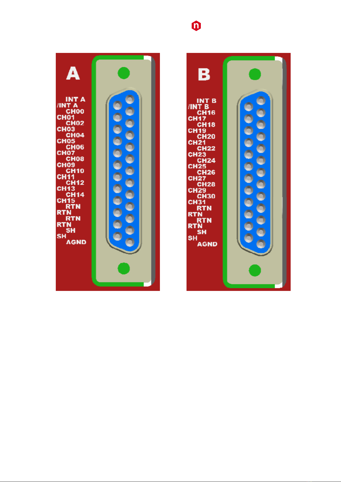
DB25 connector pin assignment ............................................................................................................................................7
Displays..................................................................................................................................................................... 8
Other components.................................................................................................................................................... 8
3. Safety and installation requirements ..................................................................................9
General safety information....................................................................................................................................... 9
Injury Precautions ..................................................................................................................................................................9
Safety Terms and Symbols on the Product ............................................................................................................... 9
Installation ................................................................................................................................................................ 9
4. Operating modes..............................................................................................................10
Output control and monitoring .............................................................................................................................. 10
Output Enable......................................................................................................................................................... 11
Grounding specifications ........................................................................................................................................ 12
Safety Earth connection .......................................................................................................................................................12
List of Figures
Fig. 1 –Mod. A154x 32, 12, 24 Channel boards ......................................................................................................................................6
Fig. 2 –DB25 connector pin assignment (32 channel version) ...............................................................................................................7
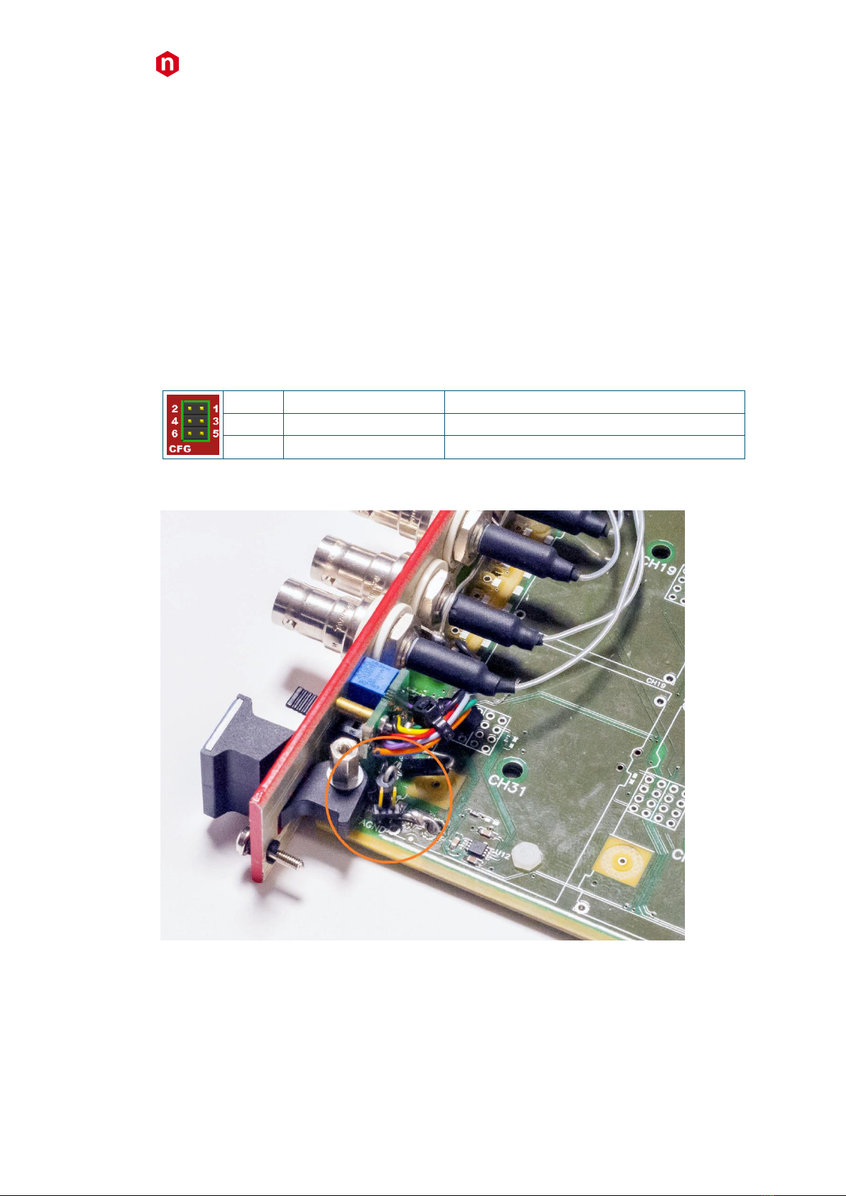
Fig. 3 –JA jumper location.......................................................................................................................................................................8
Fig. 4 –Earth configuration connection examples.................................................................................................................................13
List of Tables
Table 1 –Channel characteristics of the Mod. A1539, AG539, A154X, AG54X HV Boards ......................................................................5
Table 2 –Configuration jumpers .............................................................................................................................................................8

CAEN
Electronic Instrumentation
A1539, AG539, A154X, AG54X Power Supply Boards
4
1. Overview
Functional description
The Mod. A1539, AG539, A154X, AG54X is a family of HV boards, available with either positive or
negative polarity, compatible with the CAEN Universal Multichannel Power Supply System (SYx527).
The A1539, A154x channels share a common floating return, which allows on-detector grounding
reducing the noise level; the floating return is insulated from the crate earth up to ±50 V (with a 65 V
hardware limit); the return of the AG539, AG54x channels is wired to the crate Earth reference.
12, 24 and 32 channel versions are available; 12 channel versions output voltages are provided via SHV
connectors; 24 channel versions are available with either SHV connectors or DB25 connector; 32
channel boards have the DB25 connectors. 24 channel SHV versions are double width boards (10 TE); all
other versions are single width (5 TE).
All boards are provided with both current and voltage protections. If over-current occurs, the relevant
channel can be programmed either to turn off after a programmable trip time or to keep on providing
the maximum allowed current: this particular feature allows the modules to work as current generator
(TRIP range: 0 ÷ 999 s; 1000 s = Infinite, current generator mode. Step = 1 s). The maximum output
voltage can be fixed, through a potentiometer located on the front panel, at the same common value for
all the board channels and this value can be read out via software.
The HV RAMP-UP and RAMP-DOWN rates may be selected independently for each channel.
Some models offer dual current range, selectable via software, with increased monitor resolution for
the lower range.
The boards have also the safety board interlock: this protection allows to disable the primary HV
generation when the HV outputs are not connected to their loads.

CAEN
Electronic Instrumentation
A1539, AG539, A154X, AG54X Power Supply Boards
5
2. Technical Specifications
Channel Characteristic Table
Table 1 –Channel characteristics of the Mod. A1539, AG539, A154X, AG54X HV Boards
Version
A1539 –AG539
A1540 –AG540
A1540H
A1541 –AG541
A1542 –AG542
A1542H
Polarity
Positive / Negative / Mixed1depending on purchased version
Output Voltage
0÷100 V
0÷500 V
Max. Output
Current
High power
10 mA
1 mA
1mA
10 mA
1 mA
1 mA
High Resolution
100 µA
100 µA
Voltage Set Resolution
10 mV
Voltage Monitor Resolution
1 mV
Current Set Resolution
200 nA
20 nA
20nA
200 nA
20 nA
20 nA
Current
Monitor
Resolution
High power
10 nA
1 nA
1nA
10 nA
1 nA
1nA
High Resolution
100 pA
100 pA
VMAX hardware
0÷100 V common to all board channels
0÷500 V common to all board channels
VMAX hardware accuracy
1 V
VMAX software
0÷100 V settable for each channel
0÷500 V settable for each channel
VMAX software resolution
1 V
Ramp Up/Down
1÷50 Volt/sec, 1 Volt/sec step
1÷100 Volt/sec, 1 Volt/sec step
Voltage Ripple
<10mVpp (Max)
<5mVpp (Max)
<10mVpp (Max)
<5mVpp (Max)
Vmon vs. Vout accuracy
T.B.D.
T.B.D.
T.B.D.
T.B.D.
T.B.D.
T.B.D.
Vset Vs. Vout accuracy
T.B.D.
T.B.D.
T.B.D.
T.B.D.
T.B.D.
T.B.D.
Imon vs. Iout accuracy
T.B.D.
T.B.D.
T.B.D.
T.B.D.
T.B.D.
T.B.D.
Iset vs. Iout accuracy
T.B.D.
T.B.D.
T.B.D.
T.B.D.
T.B.D.
T.B.D.
Maximum output power
1 W/ch
0.1 W/ch
0.1 W/ch
5 W/ch
0.5 W/ch
0.5 W/ch
Consumption @ full power
32 ch: 64 W
24 ch: 48 W
12 ch: 24 W
32 ch: 6.4 W
24 ch: 4.8 W
12 ch: 2.4 W
32 ch: 6.4 W
24 ch: 4.8 W
12 ch: 2.4 W
32 ch: 320 W
24 ch: 240 W
12 ch: 120 W
32 ch: 32 W
24 ch: 24 W
12 ch: 12 W
32 ch: 32 W
24 ch: 24 W
12 ch: 12 W
1
Mixed boards have half of the channels with positive polarity and half with negative

CAEN
Electronic Instrumentation
A1539, AG539, A154X, AG54X Power Supply Boards
6
Front Panel
Fig. 1 –Mod. A15xx 32, 12, 24 Channel boards
Packaging
24 channel SHV versions are double width boards (10 TE); all other versions are single width (5 TE);
height is 6U.
External connections
The function and electro-mechanical specifications of the external connectors are listed in the following
subsections.
Version:
24, 32 channel DB25
12, 24 channel SHV
Output Channels:
FCI DBPV25S365GTLF; see below
HV coaxial connectors Radiall SHVR317580
Return & AGND:
Radiall R921921 socket, Ø 2mm (floating)
PASSIVE & SIGNAL ILK:
00-type LEMO connector
AMP 280371-2 (12 channel)

CAEN
Electronic Instrumentation
A1539, AG539, A154X, AG54X Power Supply Boards
7
DB25 connector pin assignment
Fig. 2 –DB25 connector pin assignment (32 channel version)
INT - /INT: interlock; RTN: channel return; AGND: earth; SH: connector shield; NC: not connected;

CAEN
Electronic Instrumentation
A1539, AG539, A154X, AG54X Power Supply Boards
8
Displays
HV ON LED:
Function: lights up as at least one channel is on
Type: red LEDs for positive polarity; yellow green LEDs for negative polarity.
INTERLOCK LED:
Function: lights up as the board is in INTERLOCK (channel are disabled).
Type: red LED
Other components
VMAX trimmer:
Function: it allows to adjust the hardware maximum voltage
VMAX common to all the channels. Its value can be read out
via software.
Shield CFG jumpers (24, 32 ch floating):
Function: see table below
Table 2 –Configuration jumpers
1-2
Agnd -shield
Connects Agnd (Earth) to HV cable shield
3-4
Agnd - Return
Connects Agnd (Earth) to HV channels return
5-6
Shield - Return
Connects Shield to HV channels return
JA (A15xxD):Jumper connector; short circuit: connect FAGND (Earth) and AGND (CH rtn). See below for
JA location.
Fig. 3 –JA jumper location

CAEN
Electronic Instrumentation
A1539, AG539, A154X, AG54X Power Supply Boards
9
3. Safety and installation requirements
General safety information
This section contains the fundamental safety rules for the installation and operation of the board. Read
thoroughly this section before starting any procedure of installation or operation of the product.
Injury Precautions
Review the following precautions to avoid injury and prevent damage to this product or any products
connected to it. To avoid potential hazards, use the product only as specified. Only qualified personnel
should perform service procedures.
Avoid Electric Overload.
To avoid electric shock or fire hazard, do not power a load outside of its specified range.
Avoid Electric Shock.
To avoid injury or loss of life, do not connect or disconnect cables while they are connected to a voltage
source.
Do Not Operate Without Covers.
To avoid electric shock or fire hazard, do not operate this product with covers or panels removed.
Do Not Operate in Wet/Damp Conditions.
To avoid electric shock, do not operate this product in wet or damp conditions.
Do Not Operate in an Explosive Atmosphere.
To avoid injury or fire hazard, do not operate this product in an explosive atmosphere.
Do Not Operate With Suspected Failures.
If you suspect this product to be damaged, have it inspected by qualified service personnel.
Safety Terms and Symbols on the Product
These terms may appear on the product:
DANGER indicates an injury hazard immediately accessible as you read the marking.
WARNING indicates an injury hazard not immediately accessible as you read the marking.
CAUTION indicates a hazard to property including the product.
The following symbols may appear on the product:
DANGER
WARNING
High Voltage
Refer to Manual
Installation
The Mod. A1539, AG539, A154X, AG54X are SYx527 boards. At power ON the SYSTEM, the processor will
scan all the slots in the crate to find out where the module is plugged and what kind of module it is.

CAEN
Electronic Instrumentation
A1539, AG539, A154X, AG54X Power Supply Boards
10
4. Operating modes
The Mod. A1539, AG539, A154X, AG54X boards can be controlled, either locally or remotely, through
the SYSTEM software interface. For details on SYSTEM operation, please refer to the User's Manual of
this product. The following sections contain a description of commands available for the board control
and status monitoring.
Output control and monitoring
For each output channel, it is possible, through the system, to access the following parameters:
CHANNEL NAME (settable):
descriptive name for the relevant channel
V0SET (settable):
the first of the two allowed voltage programmable values.
I0SET (settable):
the first of the two allowed current limit programmable values
V1SET (settable):
the second of the two allowed voltage programmable values
I1SET (settable):
the second of the two allowed current limit programmable values
RUp (settable):
the Ramp-Up parameter value, i.e. the maximum voltage programmable increase
rate.
RDWn (settable):
the Ramp-Down parameter value, i.e. the maximum voltage programmable
decrease rate.
TRIP (settable):
the TRIP parameter value, i.e. the maximum time an Over Current condition is
allowed to last.
SVMAX (settable):
the maximum voltage value programmable for the channel. If the value set as
SVMAX is less than the current value of the V0SET/ V1SET parameter, the latter
will automatically decrease to the SVMAX value.
VMON (monitor):
monitored voltage value
IMON (monitor):
monitored current value
STATUS (monitor):
it displays the channel status.
PW (ON/OFF):
the Power parameter shows the ON/OFF channel status. As this parameter is set
ON, the channel is switched on (if the INTERLOCK is not active and if the channel is
enabled either locally or remotely) highlighted in green when channel ON; onstate
= ON; offstate = OFF
POn (EN/DIS):
Power-On option, which can be enabled or disabled. If this option is enabled, at
Power-On or after a Restart each channel is restored in the same condition
(defined by the Power parameter) it was before the Power-Off or Reset. If this
option is disabled, at Power-On or after a Restart all the channels are off,
independently from the condition in which they were before the Power-Off or
Reset ; onstate = Enabled; offstate = Disabled
PDwn (Kill/Ramp):
Power-Down option, which can be set as KILL or RAMP. It affects the way the
channels react at a Power-Off command caused by a TRIP condition. If the KILL
option is selected, the relevant channel will be switched off at the maximum rate
available. If the RAMP option is selected, the voltage will drop to zero at a rate
determined by the value of the Ramp-Down parameter programmed for that
channel;
onstate = Ramp; offstate = Kill
TripInt:
2N-bit word (hexadecimal) maximum 16 lines, where N is the number of the
board’s Internal Trip Bus lines. Bits [0;N-1] allow the channel to sense the trip
status from the corresponding lines when set to one; in the same way, bits [N;2N-
1] allow the channel to propagate the trip status over the Trip Bus: bit N on line 0
and so on (see SY4527 User’s manual).
TripExt:
Must be set in the 0÷255 range (hexadecimal). Bits [0;3] allow the channel to
sense the trip status from the corresponding lines when set to one; in the same
way, bits [4;7] allow the channel to propagate the trip status over the trip bus: bit
4 on line 0 and so on (see SY4527 User’s manual).

CAEN
Electronic Instrumentation
A1539, AG539, A154X, AG54X Power Supply Boards
11
If the POWER ON option is enabled, as the module is turned ON, the channel is restored to the same
condition it was before the POWER OFF or RESET; if this option is disabled, at POWER ON or after a
RESET, the channel is kept OFF independently from its previous condition.
The following messages may be returned by the SYSTEM when monitoring the channel status:
OFF (channel turned OFF)
RUP (channel ramping up)
RDWN (channel ramping down)
OVC (channel in OVERCURRENT condition)
OVV (channel in OVERVOLTAGE condition)
UNV (channel in UNDERVOLTAGE condition)
2
E-TRIPPED (channel OFF due to external TRIP line signal)
3
I-TRIPPED (channel OFF due to internal OVERCURRENT condition)
EXT_DIS (channel disabled by board INTERLOCK protection)
Moreover it is possible to monitor board parameters, such as measured Temperature and HVMax, and
to check board status; the following messages may be returned by the POWER SUPPLY SYSTEM when
monitoring the board status:
UNDER_TEMP (board temperature < 5°C )
OVER_TEMP (board temperature > 65°C)
N.B.: Ax539; Ax541 and Ax542H must be operated with SYx527 ventilation fan speed set to
“High”
Output Enable
In order to enable the HV output channels, on boards with DB25 connectors, it is necessary that pin INT
and /INT are short circuited (see External connections).
Then the enable procedure is completed in one of the following ways:
Boards with LEMO interlock connectors
terminating the PASSIVE INTERLOCK (see External connections) connector on 50 Ohm.
supplying the SIGNAL INTERLOCK (see External connections) connector with a +5 V (3-
4mA) signal.
2
UNV is also reported when Hvmax limit is reached, it is up to the User to verify that VMON value does not exceed HVMAX.
3
EXTTRIP and INTTRIP parameters are expressed in Hexadecimal format

CAEN
Electronic Instrumentation
A1539, AG539, A154X, AG54X Power Supply Boards
12
Boards with AMP interlock connectors
Short circuit pin 3 and 4 [the lower ones]. Leave contact open between pin 1 (+) and 2
(-) [upper ones]
Apply +5 V (3-4mA) differential signal between pin 1 (+) and 2 (-); pin 1 is the upper
one. Leave contact open between pin 3 and 4.
The INTERLOCK LED (red) is turned off as one of the actions above is performed.
When the channels are disabled the voltage outputs drop to zero at the maximum rate available; when
the output disable cause is removed (see above), the channels remain OFF until the User turns them ON
via software..
Grounding specifications
The Mod. A1539 - A154X channels share a common floating return (FAGND, see External connections),
available on the front panel multipin connector, insulated from the crate ground (AGND, see External
connections), which is available as front panel 2mm socket connector. This feature allows on-detector
grounding, thus avoiding loops which may increase noise level. FAGND and AGND may be coupled in
several ways, according to environment requirements. Examples refer to 32 channel version.
Safety Earth connection
The connection of shield and return to Earth is fundamental for User safety.
The connection must always be at the level of detector or power supply system.
Return and Shield connections even if not present or performed incorrectly, due to protection circuits
implemented on the A1539 - A154X are bound to Earth; in this case the voltage difference between
return and Earth (System), shield and Earth is limited to approximately 50V. Please note that this is a
status of emergency-protection, not a working one. The Connector Configurator allows to optimize the
connection of the shield, of the return and of AGND (Earth). The best configuration must be determined
by the user upon application, the optimal connection depends on many characteristics of the related
experiment.

CAEN
Electronic Instrumentation
A1539, AG539, A154X, AG54X Power Supply Boards
13
The following diagrams show four examples of configuration, namely:
1. The “closed loop “ Earth configuration
2. The “closed loop “ Earth configuration, with protection stage on the load grounding
3. The “semi-open loop” Earth configuration
4. The “open loop” Earth configuration
HV Generator
Load
PMT
0
HV Channel 0
RETURN
Load
PMT
31
HV Channel 31
EARTH of
DETECTOR
Cable SHIELD
Circuit Protected
SHIELD
Circuit Protected
RETURN
HV CABLE
AGND
2 1
43
6 5
FRONT PANEL
JUMPERS
1
HV Generator
Load
PMT
0
HV Channel 0
RETURN
Load
PMT
31
HV Channel 31
EARTH of
DETECTOR
Cable SHIELD
Circuit Protected
SHIELD
Circuit Protected
RETURN
HV CABLE
AGND
2 1
43
6 5
FRONT PANEL
JUMPERS
2
HV Generator
Load
PMT
0
HV Channel 0
RETURN
Load
PMT
31
HV Channel 31
EARTH of
DETECTOR
Cable SHIELD
Circuit Protected
SHIELD
Circuit Protected
RETURN
HV CABLE
AGND
2 1
43
6 5
FRONT PANEL
JUMPERS
3
HV Generator
Load
PMT
0
HV Channel 0
RETURN
Load
PMT
31
HV Channel 31
EARTH of
DETECTOR
Cable SHIELD
Circuit Protected
SHIELD
Circuit Protected
RETURN
HV CABLE
AGND
2 1
43
6 5
FRONT PANEL
JUMPERS
4
Fig. 4 –Earth configuration connection examples

CAEN
Tools for Discovery
n
Electronic Instrumentation
A1539, AG539, A154X, AG54X Power Supply Boards
14
CAEN SpA is acknowledged as the only company in the world providing a complete range of High/Low Voltage Power
Supply systems and Front-End/Data Acquisition modules which meet IEEE Standards for Nuclear and Particle Physics.
Extensive Research and Development capabilities have allowed CAEN SpA to play an important, long term role in this field.
Our activities have always been at the forefront of technology, thanks to years of intensive collaborations with the most
important Research Centres of the world. Our products appeal to a wide range of customers including engineers, scientists
and technical professionals who all trust them to help achieve their goals faster and more effectively.
CAEN S.p.A.
CAEN GmbH
CAEN Technologies, Inc.
Via Vetraia, 11
Klingenstraße 108
1140 Bay Street - Suite 2 C
55049 Viareggio
D-42651 Solingen - Germany
Staten Island, NY 10305
Italy
Phone +49 (0)212 254 4077
USA
Tel. +39.0584.388.398
Fax +49 (0)212 25 44079
Tel. +1.718.981.0401
Fax +39.0584.388.959
Mobile +49 (0)151 16 548 484
Fax +1.718.556.9185
info@caentechnologies.com
www.caen.it
www.caen-de.com
www.caentechnologies.com
CAEN
Tools for Discovery
Electronic Instrumentation
A1539, AG539, A154X, AG54X Power Supply Boards rev. 2 - 6 May 2015
00104-13-A154X-MUTX
Copyright © CAEN SpA. All rights reserved. Information in this publication supersedes all earlier versions. Specifications subject to change without notice.
This manual suits for next models
9
Table of contents
Other Caen Power Supply manuals

Caen
Caen A7502 User manual

Caen
Caen SY 1527 Technical document

Caen
Caen A7030 User manual

Caen
Caen A1536 User manual

Caen
Caen EASY3000 Technical document

Caen
Caen SY 1527 Manual

Caen
Caen DT5519EN User manual

Caen
Caen N1471 Series Technical document

Caen
Caen 803 Series User manual

Caen
Caen A 1732 Technical document
Popular Power Supply manuals by other brands

Fairford
Fairford AGY-020 installation guide

PCB Piezotronics
PCB Piezotronics F482A20 Installation and operating manual

Andover Controls
Andover Controls CONTINUUM manual

nextys
nextys SBP200L user manual

MidNite Solar
MidNite Solar MNDC125 Instructions for use

Voodoo Lab
Voodoo Lab Pedal Power AC user manual