TBB SIES 2-4 KVA User manual
User Manual
Solar Intelligent Energy System (SIES)
Version A1.0
Date: Mar. 2018
User Manual of Solar Intelligent Energy System (SIES)
WARNING: FIRE HAZARD
SUITABLE FOR MOUNTING ON CONCRETE OR OTHER
NON- COMBUS TIBLE SURFACE ONLY
CAUTION: THE DC AND AC BREAKER MUST HAVE BEEN
TURNED OFF BEFORE SERVICING
MADE IN CHINA

User Manual of Solar Intelligent Energy System (SIES)
TBB Power Co.,Ltd
Disclaimer
Unless specially agreed in writing, TBB Power Co., Ltd.
Take no warranty as to the accuracy, sufficiency of suitability of any technical or other information
provided in this manual or other documentation.
Assumes no responsibility or liability for loss or damage, whether direct, indirect, consequential
or incidental, which might arise out of the use of such information
TBB offers standard warranty with its products, taking no responsibility for direct or indirect loss
due to equipment failure.
About this Manual
This manual describes our product features and provides procedure of installations. This manual is
for anyone intending to install our equipment.
General Instruction
Thanks for choosing our products and this manual were suitable for Solar Intelligent Energy System
(SIES).This chapter contains important safety and operation instructions. Read and keep this User
Guide well for later reference.
SIES needs to be installed by professionals and please pay attention to the following points prior to
installation:
1) Please check the input voltage or voltage of battery is same to the nominal input voltage of this
inverter.
2) Please connect positive terminal “+” of battery to “+” input of the inverter.
3) Please connect negative terminal “-” of battery to “-” input of the inverter.
4) Please use the shortest cable to connect and ensure the secure connection.
5) While connecting, please secure the connection and avoid short cut between positive terminal
and negative terminal of battery, which will cause damage of battery.
6) Inverter will have high voltage inside. Only authorized electrician can open the case.
7) The inverter WAS NOT designed to use in any life retaining equipment.

User Manual of Solar Intelligent Energy System (SIES)
Table of Contents
1. General Safety Instruction ......................................................................................................................... 1
1.1 Safety Instruction ........................................................................................................................ 1
1.2 General Precaution..................................................................................................................... 1
1.3 Precaution regarding battery operation ...................................................................................... 1
1.4 Precaution regarding photovoltaic .............................................................................................. 2
2. System Introduction ................................................................................................................................... 3
2.1 Work Modes of SIES................................................................................................................... 4
2.2 System features.......................................................................................................................... 6
2.3 Energier Pro inverter charger combination................................................................................. 7
2.4 Solar Mate MPPT charger controller .......................................................................................... 7
2.5 Smart Box (SMB)........................................................................................................................ 7
2.6 Cyber central monitor.................................................................................................................. 8
2.7 Maintenance bypass................................................................................................................... 9
2.8 Intelligent charging management................................................................................................ 9
2.9 AGS (Automatic Generator Start)............................................................................................... 9
2.10 Load management (programmable AC output).......................................................................... 9
2.11 Software configuration.............................................................................................................. 10
2.12 Naming rules of SIES................................................................................................................ 10
2.13 System scheme of SIES........................................................................................................... 12
3. Structure................................................................................................................................................... 13
3.1 SIES 2-4 KVA models............................................................................................................... 13
3.2 SIES 5-8KVA models with one Solar Mate MPPT.................................................................... 14
3.3 SIES 5-8KVA with two Solar Mate MPPT................................................................................. 15
3.4 Front panel of Energier Pro ...................................................................................................... 16
3.5 Front panel of Solar Mate MPPT.............................................................................................. 17
3.6 Smart Box (SMB)...................................................................................................................... 18
4. Installation and Connection...................................................................................................................... 20
4.1 Material list................................................................................................................................ 20
4.2 Installation Location.................................................................................................................. 21
4.3 Wires Selection......................................................................................................................... 21
4.4 Installation of SIES components............................................................................................... 22
4.5 Connection of internal cables ................................................................................................... 22
4.6 Installation of Battery ................................................................................................................ 26
4.7 Connection of external cables .................................................................................................. 28
4.8 Install GPRS Antenna............................................................................................................... 37
4.9 Install the SIM Card .................................................................................................................. 37
5. Operation and Configuration.................................................................................................................... 39
5.1 Double Checking....................................................................................................................... 39
5.2 Switch on the system................................................................................................................ 39
5.3 Configurations........................................................................................................................... 40

User Manual of Solar Intelligent Energy System (SIES)
5.4 Battery Calibration .................................................................................................................... 40
5.5 Maintenance Bypass................................................................................................................. 40
5.6 Switch off the system................................................................................................................ 41
5.7 Periodic Maintenance ............................................................................................................... 42
6. Central Monitoring and Control................................................................................................................ 43
6.1 Functions of Cyber.................................................................................................................... 43
6.2 Information displayed in Cyber ................................................................................................. 44
6.3 System Configuration................................................................................................................ 48
6.4 System Control ......................................................................................................................... 49
6.5 Wireless Communication.......................................................................................................... 52
6.6 Firmware update....................................................................................................................... 53
7. Specifications........................................................................................................................................... 54
7.1 SIES system configuration........................................................................................................ 54
7.2 Specifications of Smart Box...................................................................................................... 55
8. Trouble Shooting...................................................................................................................................... 57
8.1 Fault Codes indicated in Cyber................................................................................................. 57
8.2 Common Failure Analysis......................................................................................................... 58
9. Annex I:English Alphabets displayed by Cyber..................................................................................... 59
10. Annex II: Setting codes and functions.............................................................................................. 60

User Manual of Solar Intelligent Energy System (SIES)
TBB Power Confidential Page 1of 66
1. General Safety Instruction
1.1 Safety Instruction
As dangerous voltages and high temperature exist within the Solar Intelligent Energy System (SIES),
only qualified and authorized maintenance personnel are permitted to open and repair it. Please
make sure SIES system is turned off before open and repair it.
This manual contains information concerning the installation and operation of SIES system. All
relevant parts of the manual should be read prior to commencing the installation. Please follow the
local stipulation meantime.
Any operation against safety requirement or against design, manufacture, safety standard, and are
out of the manufacturer warranty.
1.2 General Precaution
Do not expose to dust, rain, snow or liquids of any type, it is designed for indoor use. DO NOT block
off ventilation, otherwise SIES system would be overheating.
To avoid fire and electric shock,make sure allcables selected with right gaugeand being connected
well. Smaller diameter and broken cable are not allowed to use.
Please do not put any inflammable goods near to SIES system.
Never place unit directly above batteries, gases from a battery will corrode and damage energy
storage system.
1.3 Precaution regarding battery operation
Use plenty of fresh water to clean in case battery acid contacts skin, clothing, or eyes and consult
with doctor as soon as possible.
The battery may generate flammable gas during charging. Provide adequate ventilation during
charging. NEVER smoke or allow a spark or flame in vicinity of a battery.
Do not put the metal tool on the battery; spark and short circuit might lead to explosion.

User Manual of Solar Intelligent Energy System (SIES)
TBB Power Confidential Page 2of 66
REMOVE all personal metal items such as rings, bracelets, necklaces, and watches while working
with batteries. Batteries can cause short-circuit current high enough to make metal melt, and could
cause severe burns.
A battery circuit breaker was built in the intelligent power distribution box.
1.4 Precaution regarding photovoltaic
Photovoltaic produce electrical power when exposedto light andcancausean electricshock, energy,
or fire hazard. Series fuse protection or PV box maybe required, depending on the type and
configuration of the photovoltaic used in system. Series fuse, diodes and PV circuit breaker were
built in our PV box.

User Manual of Solar Intelligent Energy System (SIES)
TBB Power Confidential Page 3of 66
2. System Introduction
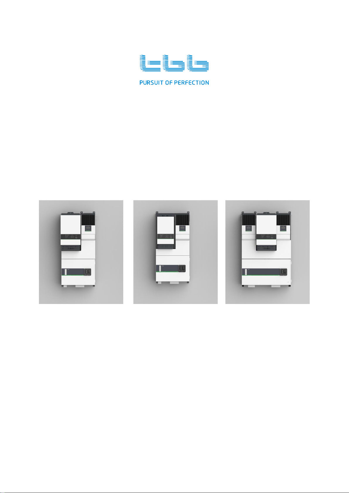
SIES is a self-consumption hybrid PV system developed by TBB power. Working together with
various kinds of battery, SIES can take advantage of energy from sun, grid or generator, in order to
realize energy independent. With built-in AGS (Automatic Generator Start) function, SIES can
automatically start or stop generator.
As an independent power solution for household and small business, SIES assures you the
continuous power and immunes to power shedding or blackout. It is the reliable solution for areas
where have no power supply or suffer electricity shortage.
Combined of MPPT charge controller, heavy duty bi-directional inverter, energy management
system, energy meters, circuit breakers and central monitor, SIES is a fully integrated system with
all components well configured and programmed.
Designed with the concept of ”Plug and Play”, it requires no further configuration and much less
connection effort. System installation is quite easy and system performance is strengthened
accordingly.
Figure 1 Overall appearance of SIES

User Manual of Solar Intelligent Energy System (SIES)
TBB Power Confidential Page 4of 66
Table 1 Configuration of SIES system
Items
System Components
A
Energier Pro bi-directional inverter
B
Solar Mate MPPT charge controller
C
Cyber(central monitoring)
D
Smart Box
2.1 Work Modes of SIES
SIES has multiple work modes, which can be configured through SmartPhone APP or Web-based
Monitoring Platform.
2.1.1 Solar Hybrid mode
This work mode is for those areas suffering from frequent power shedding. Energy from solar will be
the prioritized source for powering the loads and meanwhile charging the battery. When it is sunset
and grid is available, grid will be major source to power the loads and charge battery. Only if there
is power blackout, will battery be discharged to power the loads.
Table 2 Solar Hybrid mode
Work Mode
Priorities of Energy
Source
Description
Solar Hybrid
Solar > Grid > Battery
1. During daytime, Solar Energy has priority to power the loads
and at the same time charge battery.
2. If Solar Energy is not sufficient and grid is available, the grid
will be introduced to power the loads and charge battery.
3. Upon power blackout, battery will be discharged to power the
loads.
2.1.2 Energy Storage mode
There are two scenarios:
2.1.2.1 Scenario A: Grid is not available
This work mode is mainly working for areas without grid. Energy from solar is the prioritized source
for powering the loads and meanwhile charging the battery. When it is sunset, battery will be
discharged to power the loads. If battery has been deeply discharged, SIES will start the diesel
generator in order to power the loads and meanwhile charge the battery.
User Manual of Solar Intelligent Energy System (SIES)
TBB Power Confidential Page 5of 66
Table 3 Energy Storage mode: Grid is not available
Work Mode
Priorities of Energy Source
Description
Energy Storage
(A)
Solar > Battery > Generator
1. During daytime, Solar Energy has priority to
power the loads and at the same time charge
battery.
2. If Solar Energy is not sufficient, battery will be
discharged to power the loads.
3. When battery is discharged to low voltage level,
generator will be automatically started to power
the loads and charge the battery.
2.1.2.2 Scenario B. Grid is available but not the preferred energy source
This work mode can also be useful for areas where have grid but the people want to be independent
from grid. Energy from solar will be the prioritized source for powering the loads and meanwhile
charging the battery. When it is sunset, battery will be discharged to power the loads. Only if battery
is deeply discharged, grid will be introduced to power the loads. Furthermore, the system can be
configured whether the power from gird will be used for charging battery or completely not.
Table 4 Energy Storage mode: Grid is available but not the preferred energy source
Work Mode
Priorities of Energy
Source
Description
Energy Storage
(B)
Solar > Battery > Grid
1. During daytime, Solar Energy has priority to power the
loads and at the same time charge battery.
2. If Solar Energy is not sufficient, battery will be
discharged to power the loads.
3. When battery is discharged to low voltage level, grid
will be introduced to power the loads and charge the
battery.
2.1.3 Power Backup mode
This work mode is aiming at those area suffering occasional power blackout. Grid is the main power
source, and PV and grid will charge the battery together. Battery is to be discharged to power the
loads only if there is power blackout.
Table 5 Power Backup mode
Work Mode
Priorities of Energy
Source
Description
Power Backup
Grid > Battery
1. Grid will be major power source for powering loads. PV
and grid charge the battery together.
2. Upon power blackout, battery will be discharged to power
the loads.

User Manual of Solar Intelligent Energy System (SIES)
TBB Power Confidential Page 6of 66
2.2 System features
High performance inverter
Energier Pro series bi-directional inverter generates true sine-wave alternative current (AC) so that
it can reliably power all kind of home appliances, such as TV, washing machine, electrical stove,
microwave, water pump and air conditioner, etc. Thanks to its industrial leading efficiency, the SIES
system can efficiently manage the energy flow and help you save energy.
More information about Energier Pro, please refers to the dedicated user manual of Energier Pro.
High system efficiency
Solar Mate series MPPT charge controller of SIEShas a peak efficiencyup to 98%. Maximum Power
Point Tracking (MPPT) technology can increase the energy generation of PV panel by more than
30%, especially when the sun irradiation is at low level, for example sunrise or cloudy day etc. Solar
Mate is a multi-voltage MPPT charge controller with sophisticated battery charging algorithm for lead
acid battery or lithium-ion battery.
Energier Pro series bi-directional inverter of SIES features high conversion efficiency up to 94% and
extraordinary low zero-load power consumption, therefore the SIES can make full advantage of the
energy harvested from the sun.
Intelligent energy management
According to the chosen work mode, SIES will automatically monitor and manage the energy flow.
Energy generated by PV system and from grid or generator will be converged and optimized to a
maximum extent.
Comprehensive monitoring
SIES offers comprehensive monitoring of whole system. Cyber central monitor displays all
information including energy generation, energy consumption and battery state of charge (SoC), etc,
clearly and in real time.
Besides, as a web-based remote monitoring platform, TBB Energy Management Solution (TEMS)
meets more advancedrequirement on monitoringand control. Abundant system data of SIES system
can be remotely monitored through GPRS or WIFI connections, and the system can be remotely
configured and operated.
Quick installation design
Designed with the concept of “Plug and Play”,the SIES system can be installed quickly with minimum
time, labor and footprint.
User Manual of Solar Intelligent Energy System (SIES)
TBB Power Confidential Page 7of 66
2.3 Energier Pro inverter charger combination
Energier Pro bi-directional inverter is a new generation inverter charger combination, which
integrates a powerful battery charger, true sine wave inverter and a high speed AC transfer switch
into a single enclosure. Meantime, its multiple energy management functions / accessories enables
the users to configure advanced hybrid independent power systems for various applications.
For detailed information of Energier Pro, please refer to its user manual.
2.4 Solar Mate MPPT charger controller
Solar Mate MPPT charge controller is a solar charge controller with built-in Maximum Power Point
Tracking (MPPT) technology, which can optimize the PV’s output by eliminating the fluctuation due
to shading or temperatures variation. It tracks the maximum power point of a PV array in order to
deliver the maximum charging current to battery, so that the energy generation of PV array can be
significantly increased by as much as 30% comparing with PWM technology.
For detailed information of Solar Mate, please refer to its user manual.
2.5 Smart Box (SMB)
Smart Box is an intelligent power distribution box, which was designed with the target not only to
simplify the installation of SIES system, but also strengthen the system functions with built-in
components such as MEDU (Multiple Energy Detection Unit), circuit breakers, central monitor and
maintenance bypass, etc.
Smart Box contains the following components:
Table 6 Components of Smart Box
Category
Device
AC input
Circuit breaker, SPD, Terminals
AC output
Residual current device, Manual Bypass Circuit Breaker, Load Management Unit,
Terminals
PV input
Circuit Breaker and relevant Terminals
Battery
Circuits Breaker and relevant Terminals
MEDU is the energy detection unit, which collects the status information from the following
components and communicates with Cyber central monitor. Its functions are described as following
table.

User Manual of Solar Intelligent Energy System (SIES)
TBB Power Confidential Page 8of 66
Table 7 Functions of MEDU
Category
Functions
AC input
Measure voltage, current, frequency, power and KWh
AC output
Measure voltage, current, frequency, power and KWh
Battery
Measure SoC, charging and discharging current, voltage, temperature,
charging and discharging KWh
Load
management
Measure the power and KWh of programmable AC output L2 and L3.
Users or installers can program the work logic of two AC outputs L2 and L3,
based on multiple conditions: length of time, power, battery SoC, interlock and
consumed energy in KWh.
2.6 Cyber central monitor
Thanks to T-Bus communication protocol, Cyber can display the work status of all system
components in real time, including PV array, inverter charger combination, battery and loads.
In the middle of LCD screen of Cyber, there are two green triple arrows and one blue triple arrow
which indicate the energy flows. These two energy flow bars display the system status in real time,
and are explained in detail in chapter 6.
Figure 2 Cyber the central monitor of SIES
Table 8 Functions of Cyber
Category
Functions
Monitoring
Energier Pro bi-directional inverter, Solar Mate MPPT charge controller,
Battery and Load
Configuration
Battery Type, Battery Capacity
Control
Battery Equalization
Communication
Built-in Bluetooth, optional GPRS or WIFI
Others
Calendar, Clock
User Manual of Solar Intelligent Energy System (SIES)
TBB Power Confidential Page 9of 66
2.7 Maintenance bypass
Upon failure of Energier Pro, the Maintenance Bypass, which is located in Smart Box, can be used
for the purpose of system maintenance. As a result, on one side, the Energier Pro can be safely
dismantled from the rest of SIES for further examining and repairing, and on another side, the loads
can be continually powered by available grid or generator.
Please refer to Chapter 5.5 for more details of maintenance bypass.
This operation might damage bi-directional inverter, and can ONLY be performed by
professional. The failure of inverter due to unauthorized operation is out of warranty.
2.8 Intelligent charging management
SIES coordinates the battery charging from two chargers (Battery charger of Energier Pro and Solar
Mate MPPT charge controller) and charges battery according to multiple parameters related with
battery. Energy generated from PV array will be prioritized power source and grid as supplement
one, as a result the charging current won’t exceed the limit.
2.9 AGS (Automatic Generator Start)
With the built-in AGS function, SIES can automatically start the generator once the predefined
conditions are met. The conditions can be battery voltage, power of loads and length of time. A
software for Windows system is provided to easily program the conditions of starting and stopping
generator.
2.10 Load management (programmable AC output)
AC outputs L2 and L3 are for smart load control and can be programmed to control the specific loads,
for example air conditioner, water heater, etc. The load control can be based on combination of
conditions such as load power, battery SoC, length of time, or accumulated energy consumption of
relevant load.
Table 9 Load Management
Category
Condition
Action
Resume
Power
Load power >= set value
Switch off
Press FUNC switch in Cyber
Battery SoC
SoC <= set value
Switch off
Resume output when battery SoC is 10%
higher than the set value
Length of Time
Exceeds the set value
Switch off
KWh
Consumed maximum KWh
per setting
Switch off
Automatically resume in a new day cycle

User Manual of Solar Intelligent Energy System (SIES)
TBB Power Confidential Page 10 of 66
2.11 Software configuration
SIES is fully programmable through web-based platform, for the following functions or parameters:
System work modes
AC input parameters
Inverter parameters
Battery parameters
Battery charging parameters
Automatic Generator Start (AGS)
Load management
2.12 Naming rules of SIES
2.12.1 Models of SIES
The following naming rules are applied on models of SIES:
Figure 3 Naming rules of SIES

User Manual of Solar Intelligent Energy System (SIES)
TBB Power Confidential Page 11 of 66
Table 10 Naming rules of SIES
Field
Figures
Explanation
SIES
SIES
Series Name
AA
20
Inverter Power
2000VA
30
3000VA
40
4000VA
50
5000VA
60
6000VA
80
8000VA
BB
15
Max. AC charge current
15A
20
20A
30
30A
40
40A
45
45A
50
50A
60
60A
90
90A
C
L
Rated DC voltage
12V
M
24V
S
48V
DD
60
Max solar charge current
60A
60x2
2pcs 60A
EEEE
N.A.
Communication Type
Bluetooth
GPRS
GPRS and Bluetooth
WIFI
Wi-Fi and Bluetooth
2.12.2 Models of Smart Box
The following naming rules are applied on models of Smart Box
Table 11 Naming rules of Smart Box
Field
Figures
Explanation
SMB
SMB
Series name
AA
30
Max inverter Power
3000VA
40
4000VA
80
8000VA
B
L
Rated DC voltage
12V
M
24V
S
48V
User Manual of Solar Intelligent Energy System (SIES)
TBB Power Confidential Page 12 of 66
CC
60
Max solar charge current
60A
60x2
2pcs 60A
DDDD
N.A.
Communication Type
Bluetooth
GPRS
GPRS and
Bluetooth
WIFI
Wi-Fi and Bluetooth
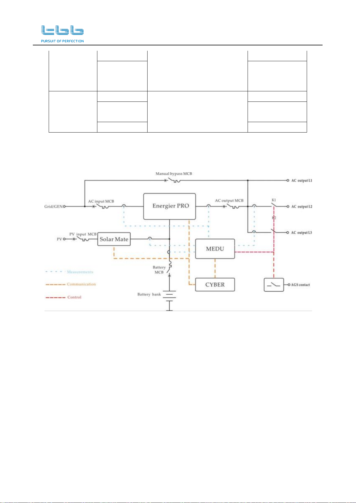
2.13 System scheme of SIES
Figure 4 System scheme of SIES

User Manual of Solar Intelligent Energy System (SIES)
TBB Power Confidential Page 13 of 66
3. Structure
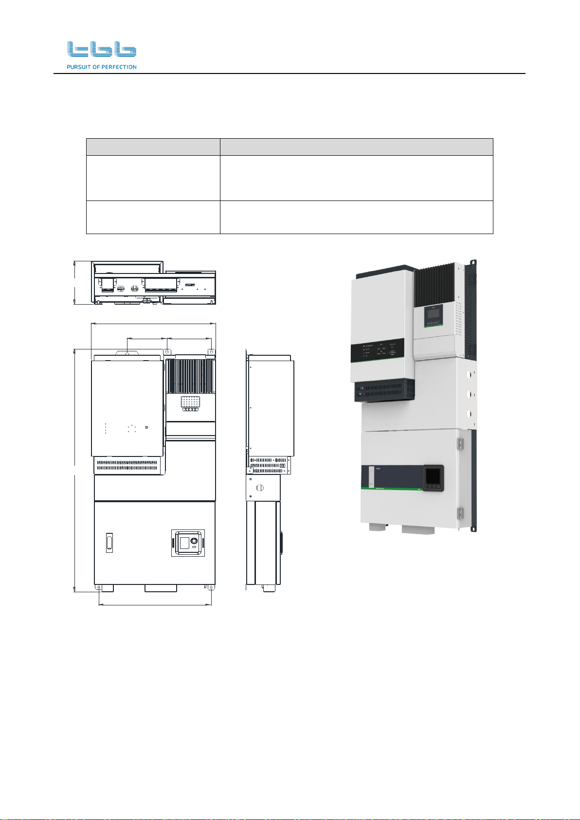
3.1 SIES 2-4 KVA models
Table 12 SIES 2-4 KVA models
System Components
Product Models
Energier Pro
Bi-directional Inverter
12V models: CF2060L; CF3090L;
24V models: CF2030M; CF3045M
48V models: CF2015S; CF3020S; CF4030S
Solar Mate
MPPT Charge Controller
12V / 24V / 48V model: SP60-150
445
475
1026,9
442,5
173,5
Figure 5 Dimension of SIES 2-4 KVA models
User Manual of Solar Intelligent Energy System (SIES)
TBB Power Confidential Page 14 of 66
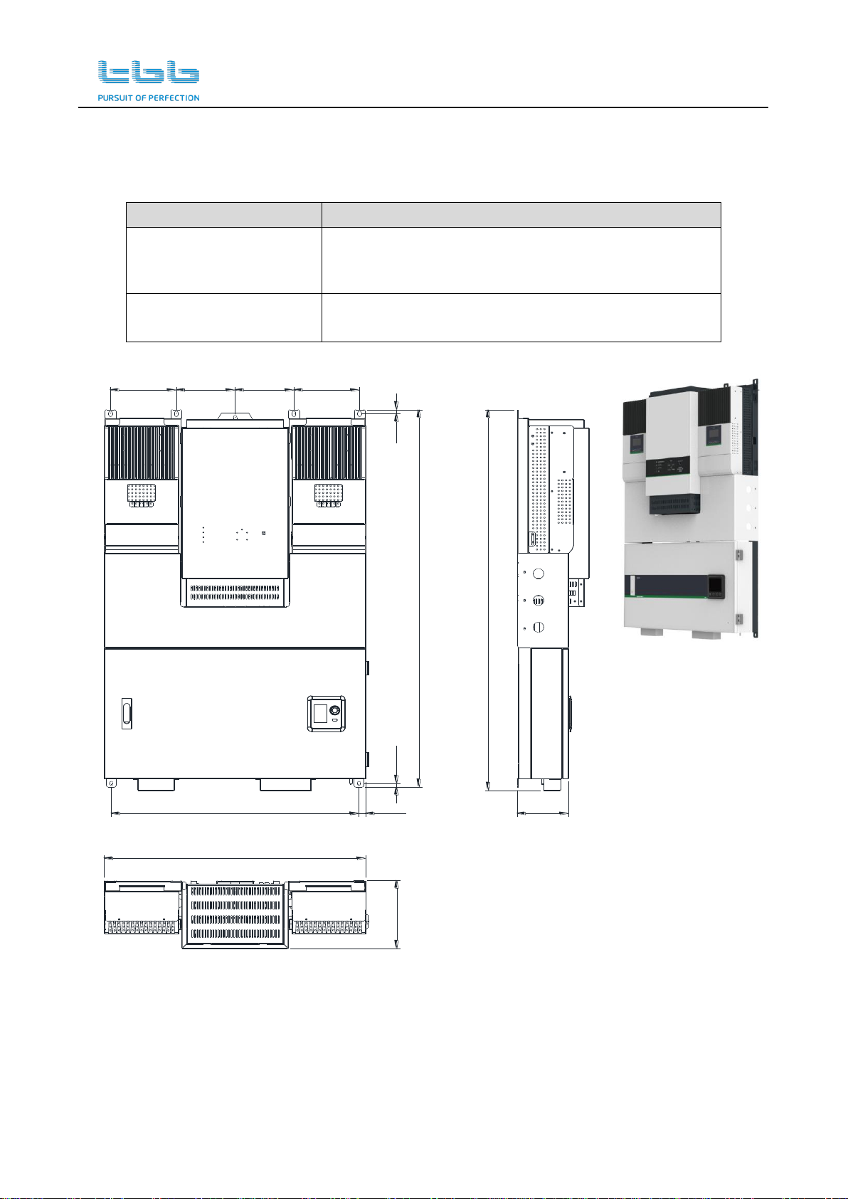
3.2 SIES 5-8KVA models with one Solar Mate MPPT
Table 13 SIES 5-8KVA models with one Solar Mate MPPT
System Components
Product Models
Energier Pro
Bi-directional Inverter
24V models: CF5090M
48V models: CF6050S, CF8060S
Solar Mate
MPPT Charge Controller
12V / 24V / 48V model: SP60-150
157,5 176
444,5
1076,4
191,5
492,7
Figure 6 Dimension of SIES 5-8KVA models with one Solar Mate MPPT
User Manual of Solar Intelligent Energy System (SIES)
TBB Power Confidential Page 15 of 66
3.3 SIES 5-8KVA with two Solar Mate MPPT
Table 14 SIES 5-8KVA with two Solar Mate MPPT
System Components
Product Models
Energier Pro
Bi-directional Inverter
48V models: CF6050S, CF8060S
Solar Mate
MPPT Charge Controller
12V / 24V / 48V model: SP60-150 x 2
138.3
1076.5
192.6
1067
10.5 12
700
18.5663
157.5 176157.5176
Figure 7 Dimension of SIES 5-8KVA with two Solar Mate MPPT
This manual suits for next models
1
Table of contents
Other TBB Power Supply manuals


