Thermal Instrument Co. 9200B User manual

9200B
FLOW COMPUTER
99764 02/05/01
Thermal Instrument Company, Inc.
217 Sterner Mill Road, Trevose, PA 19053
Phone: (215) 355-8400 Fax: (215) 355-1789
Email: [email protected]

SAFETY INSTRUCTIONS
The following instructions must be observed.
• This instrument was designed and is checked in accordance with regulations in force EN 60950 (“Safety of
information technology equipment, including electrical business equipment”).
A hazardous situation may occur if this instrument is not used for its intended purpose or is used incorrectly.
Please note operating instructions provided in this manual.
• The instrument must be installed, operated and maintained by personnel who have been properly trained.
Personnel must read and understand this manual prior to installation and operation of the instrument.
• This instrument is internally fused. Replace the internal fuse with the following specified type and rating only:
Input Power Recommended Fuse
115 VAC 160 mA slow blow fuse
230 VAC 80 mA slow blow fuse
12-24 VDC 800 mA slow blow fuse
Disconnect power supply before replacing fuse!
• The manufacturer assumes no liability for damage caused by incorrect use of the instrument or for modifications
or changes made to the instrument.
Symbols Used On Unit
Number Symbol Publication Description
1IEC 417, No. 5031 Direct current
2IEC 417, No. 5172 Equipment protected throughout by DOUBLE
INSULATION or REINFORCED INSULATION
(equivalent to Class II of IEC 536–see annex H)
3
!
ISO 3864, No. B.3.1 Caution (refer to accompanying documents)
Technical Improvements
• The manufacturer reserves the right to modify technical data without prior notice.
Proprietary Notice
Theinformationcontainedinthispublicationisderivedinpartfromproprietaryandpatentdata. Thisinformationhasbeen
preparedfortheexpressedpurposeofassistingoperatingandmaintenancepersonnelintheefficientuseoftheinstrument
describedherein. Publicationofthisinformationdoesnotconveyanyrightstouseorreproduceitortouseforanypurpose
other than in connection with the installation, operation and maintenance of the equipment described herein.
Copyright 1995
Printed in USA. All Rights Reserved.
WARNING!
This instrument contains electronic components that are susceptible to damage by static electricity. Proper handling*
procedures must be observed during the removal, installation, or handling of internal circuit boards or devices.
*Handling Procedure
1. Power to unit must be removed.
2. Personnel must be grounded, via wrist strap or other safe, suitable means, before any printed circuit board or other
internal device is installed, removed or adjusted.
3. Printed circuit boards must be transported in a conductive bag or other conductive container. Boards must not be
removedfrom protectiveenclosure untiltheimmediate timeof installation. Removedboardsmust beplaced immediately
in protective container for transport, storage, or return to factory.
Comments
ThisinstrumentisnotuniqueinitscontentofESD(electrostaticdischarge)sensitivecomponents. Mostmodernelectronic
designs contain components that utilize metal oxide technology (NMOS, CMOS, etc.). Experience has proven that even
smallamountsofstaticelectricitycandamageordestroythesedevices. Damagedcomponents,eventhoughtheyappear
to function properly, may exhibit early failure.
!
!

68
9200B Flow Computer
1. DESCRIPTION
1.1 Unit Description ...............................................................................................1
1.2 Unit Features...................................................................................................1
1.3 Specifications ..................................................................................................2
2. INSTALLATION
2.1 General Mounting Hints...................................................................................6
2.2 Mounting Diagrams .........................................................................................6
3. APPLICATIONS
3.1 Gas/Liquid Volume ..........................................................................................7
3.2 Corrected Liquid Volume .................................................................................8
3.3 Liquid Mass .....................................................................................................9
3.4 Batching ........................................................................................................10
4. WIRING
4.1 Typical Wiring ................................................................................................11
5. UNIT OPERATION
5.1 Front Panel Operation Concept for Run Mode..............................................12
5.2 General Operation.........................................................................................13
5.3 Ratemeter/Totalizer Operation ......................................................................13
5.3.1 Password Protection for Rate/Total mode ......................................13
5.3.2 Relay Operation in Rate/Total mode...............................................13
5.3.3 Pulse Output in Rate/Total mode....................................................13
5.3.4 Analog Output in Rate/Total mode..................................................13
5.3.5 RS-232 Serial Port Operation in Rate/Total mode.........................14
5.3.6 RS-485 Serial Port Operation in Rate/Total mode.........................14
5.4 Batcher Operation .........................................................................................15
5.4.1 Batcher Configuration.....................................................................15
5.4.2 Password Protection for Batcher mode ..........................................16
5.4.3 Relay Operation in Batcher mode ..................................................16
5.4.4 Pulse Output in Batcher mode.......................................................16
5.4.5 Analog Output in Batcher mode......................................................16
5.4.6 RS-232 Serial Port Operation in Batcher mode.............................17
5.4.7 RS-485 Serial Port Operation in Batcher mode.............................17
6. PROGRAMMING
6.1 Front Panel Operation Concept for Program Mode.......................................18
6.2 Setup Menus .................................................................................................19
6.3 Setup Sub-Menus..........................................................................................20
6.3.1 INSTRUMENT TYPE......................................................................20
6.3.2 SELECT FLOW EQUATION...........................................................21
6.3.3 SETUP INDICATORS (Total)..........................................................21
6.3.4 SETUP INDICATORS (Density) .....................................................21
6.3.5 SETUP INDICATORS (Rate)..........................................................22
6.3.6 SETUP INDICATORS (Temperature) .............................................22
6.3.7 SETUP FLOW INPUT (Pulse - Ain & PS (A=B)) ............................23
6.3.8 SETUP FLOW INPUT (Pulse - Quadrature, Qx1 or Qx2) ..............24
6.3.9 SETUP FLOW INPUT (Analog) ......................................................25
6.3.10 SETUPAUX INPUT......................................................................26
6.3.11 SET FLUID PROPERTIES ...........................................................27
6.3.12 SETUP PULSE OUTPUT .............................................................27
6.3.13 SETUPANALOG OUTPUT ..........................................................28
6.3.14 SETUP RELAYS...........................................................................28
6.3.15 SETUP CONTROL INPUTS(RATE/TOTAL) ................................ 30
6.3.16 SETUP CONTROL INPUTS(BATCH)...........................................30
6.3.17 SETUP REALTIME CLOCK(Time) ...............................................31
6.3.18 SETUP REALTIME CLOCK(Date)................................................31
6.3.19 SERIAL USAGE ...........................................................................32
6.3.20 SET DATALOG/PRINT(Configure) ...............................................33
6.3.21 SET DATALOG/PRINT (Select_list) .............................................34
6.3.22 ADMINISTRATIVE SETUP ...........................................................34
6.3.23 SETUP NETWORK CARD ...........................................................35
CONTENTS
i

69
9200B Flow Computer
CONTENTS
ii
7. PRINCIPLE OF OPERATION
7.1 General..........................................................................................................36
7.2 Orifice Flowmeter Considerations .................................................................36
7.3 Flow Equations..............................................................................................36
7.4 Calculating the Expansion Factor..................................................................39
7.5 Computation of Viscosity Coef.A and B........................................................40
7.6 Linearization Table ........................................................................................41
7.6.1 Linearization Table General Information.........................................41
7.6.2 Linearization Table for Pulse Inputs................................................41
7.6.3 Linearization Table for Analog Inputs..............................................41
7.6.4 Linearization Table Interpolation.....................................................41
8. TEST, SERVICE and MAINTENANCE
8.1 Test Menus ....................................................................................................42
8.2 Test Sub-Menus ............................................................................................43
8.2.1 Audit Trail........................................................................................43
8.2.2 Error History ...................................................................................43
8.2.3 Print System Setup.........................................................................43
8.2.4 Keypad test.....................................................................................44
8.2.5 Display test .....................................................................................44
8.2.6 Calibrate CH1 0mA.........................................................................45
8.2.7 Calibrate CH1 20mA.......................................................................45
8.2.8 Calibrate CH2 0mA.........................................................................46
8.2.9 Calibrate CH2 20mA.......................................................................46
8.2.10 Calibrate CH1 0V..........................................................................47
8.2.11 Calibrate CH1 10V........................................................................47
8.2.12 Calibrate CH2 0V..........................................................................48
8.2.13 Calibrate CH2 10V........................................................................48
8.2.14 Calibrate 100 ohm RTD................................................................48
8.2.15 Calibrate 4mA Out ........................................................................49
8.2.16 Calibrate 20mA Out ......................................................................49
8.2.17 Analog In Test ...............................................................................49
8.2.18 Pulse input test .............................................................................50
8.2.19 Analog out test..............................................................................50
8.2.20 Excitation out test .........................................................................50
8.2.21 Pulse out test................................................................................51
8.2.22 Relay test.....................................................................................51
8.2.23 Control input test ..........................................................................51
8.2.24 Battery Voltage test ......................................................................52
8.2.25 Data logger utility..........................................................................52
8.3 Internal Fuse Replacement ...........................................................................53
9. RS-232 SERIAL PORT
9.1 RS-232 Serial Port Description .....................................................................54
9.2 Instrument Setup by PC Over Serial Port......................................................54
9.3 Operation of Serial Communication Port with Printers ..................................54
9.4 9200B Flow Computer RS-232 Port Pinout...................................................54
10. RS-485 SERIAL PORT
10.1 RS-485 Serial Port Description ...................................................................55
10.2 General........................................................................................................55
10.3 Operation of Serial Communication Port with PC .......................................55
10.4 9200B Flow Computer RS-485 Port Pinout.................................................55
11. FLOW COMPUTER SETUP SOFTWARE
11.1 System Requirements .................................................................................56
11.2 Cable and Wiring Requirements..................................................................56
11.3 Installation for Windows™3.1 or 3.11 ..........................................................56
11.4 Using the Flow Computer Setup Software ..................................................57
11.5 File Tab ........................................................................................................57
11.6 Setup Tab.....................................................................................................57
11.7 View Tab ......................................................................................................58
11.8 Misc. Tab......................................................................................................58
12. GLOSSARY OF TERMS
12 Glossary Of Terms..........................................................................................59
13. DIAGNOSIS AND TROUBLESHOOTING
13.1 Response of 9200B Flow Computer on Error or Alarm: ..............................63
13.2 Diagnosis Flow Chart and Troubleshooting.................................................64
13.3 Error & Warning Messages: ........................................................................65
13.3.1 Sensor/Process Alarms ................................................................65
13.3.2 Self Test Alarms............................................................................66

1
9200B Flow Computer
Unit Description 1. Description
1.1 Unit Description:
The 9200B is a special purpose flow computer intended for use with
Thermal Mass Flowmeters. The units of measure for flow rate and total
can be entered by the user. An auxillary, internal, high current, DC
power supply is provided to power the Thermal Mass Flowmeters.
The 9200B accepts analog input from Thermal Mass Flowmeter and
provides linearization of the sensor and scaling to the flow rate and total
indicators. A variety of pulse output, analog outputs, control inputs, relay
alarms, and RS-232 outputs are provided standard. RS-485 Modbus
RTU is also an ordering option.
Enclosures are available suitable for panel, wall (Nema 4), benchtop,
and explosion proof enclosure (Class 1 Div 1 Groups C+D) mounting
schemes.
1.2 Unit Features:
The 9200B Flow Computer offers the following features:
• ThermalMass FlowmeterInput
• ProvidesIsolated 24VDCOutputat600mAtoPower
ThermalMass Flowmeter
• TwoLine LCDDisplay
• MultipleInstrument Functions
• MenuSelectable Hardware&SoftwareFeatures
• IsolatedOutputs Standard
• VersatileRS-232 PortStandard
• DINEnclosure withTwoPieceConnector
• OptionalNetworking Cards
• AdvancedBatching Features
• AlsoSuitable forUsewithVolumetricFlowmeterTypes
Unit Features

2
9200B Flow Computer
1.3 Specifications:
Specifications:
Flow Meters and Computations
Meter Types: Thermal Mass flowmeters plus all linear
pulse and square law meters supported including:
vortex, turbine, magnetic, PD, target, orifice, venturi
and many others
Linearization: Square root, 16 point table or UVC
table
Computations: Volume, Corrected Volume & Mass
Fluid Computations: Temperature, Density, Viscosity
and API 2540 for petroleum.
Environmental
Operating Temperature: 0°C to +50°C
Storage Temperature: -40°C to +85 C
Humidity : 0-95% Non-condensing
Materials: U.L. approved
Listing: UL/CUL Listed (File No. E192404), CE
Compliant
Display
Type: 2 lines of 20 characters, Backlit LCD
Character Size: 0.3" nominal
User programmable label descriptors and units of
measure
Keypad
Keypad Type: Membrane Keypad with 16 keys
Enclosure
Size: See Dimensions
Depth behind panel: 6.5" including mating connector
Type: DIN
Materials: Plastic, UL94V-0, Flame retardant
Bezel: Textured per matt finish
Real Time Clock
The 9200B is equipped with a battery backed real
time clock with display of time and date.
Format:
12 or 24 hour time display
Day, Month, Year date display
Power Input
The factory equipped power option is internally fused.
An internal line to line filter capacitor and MOV are
provided for added transient suppression.
110 VAC Power: 85-127 Vrms, 50/60Hz (11.0 VA)
220 VAC Power: 170-276 Vrms, 50/60Hz (11.0 VA)
Flow Inputs:
Analog Input:
Accuracy: 0.02% FS at 20°C
Ranges
Voltage: 0-40 VDC, 0-20 VDC, 4-20 VDC
Current: 4-20 mA, 0-20 mA
Basic Measurement Resolution: 16 bit
Update Rate: 4 updates/sec
Automatic Fault detection: Signal over/under-range,
Current Loop Broken
Calibration: Software Calibration (no trimmers) and
Auto-zero Continuously
Extended calibration:
Learns Zero and Full Scale of each range
using special test mode.
Fault Protection:
Reverse Polarity: No ill effects
Over-Voltage Limit: 50 VDC Over voltage
protection
Over-Current Protection: Internally current
limited protected to 24VDC
Pulse Inputs:
Number of Flow Inputs: one with or without
quadrature
Input Impedance: 10 KΩnominal
Pullup Resistance: 10 KΩto 5 VDC (menu
selectable)
Pull Down Resistance: 10 KΩto common
Trigger Level: (menu selectable)
High Level Input
Logic On: 3 to 30 VDC
Logic Off: 0 to 1 VDC
Low Level Input (mag pickup)
Sensitivity:
10 mV or 100 mV
Minimum Count Speed:
Menu selectable down to 0.01 Hz
Maximum Count Speed:
Menu Selectable: 40Hz, 3000Hz or 20
kHz
Overvoltage Protection: 50 VDC
Auxiliary / Compensation Input
The auxiliary/compensation input is menu selectable
for temperature, density or not used. This input is
used for the compensated input when performing
compensated flow calculations. It can also be used
as a general purpose input for display and alarming.
Operation: Ratiometric
Accuracy: 0.01% FS at 20°C
Basic Measurement Resolution:
16 bit
Update Rate: 1 update/sec minimum
Automatic Fault detection:
Signal Over-range/under-range
Current Loop Broken
RTD short
RTD open
Fault mode to user defined default settings
Fault Protection:
Reverse Polarity: No ill effects
Over-Voltage Limit (Voltage Input): 50 VDC
Available Input Ranges
Voltage: 0-10 VDC, 0-5 VDC, 1-5 VDC
Current: 4-20 mA, 0-20 mA
Resistance: 100 Ohms DIN RTD
100 Ohm DIN RTD
(DIN 43-760, BS 1904):
Three Wire Lead Compensation
Internal RTD linearization learns ice point
resistance
1 mA Excitation current with reverse polarity
protection
Temperature Resolution: 0.01 C
Control Inputs
Switch Inputs are menu selectable for Start, Stop,
Reset, Lock, Inhibit, Alarm Acknowledge, Print or
Not Used.
Control Input Specifications
Input Scan Rate: 10 scans per second
Logic 1: 4 - 30 VDC
Logic 0: 0 - 0.8 VDC
Input Impedance: 100 KΩ
Control Activation:
Positive Edge or Pos. Level based on product
definition for switch usage.

3
9200B Flow Computer
Excitation Voltage
Menu Selectable: 5, 12, 24 VDC @ 100 mA (fault
protected)
Auxillary DC Supply with High Current Capability
24 VDC 420 mA (600 mA Peak)
Relay Outputs
The relay outputs are menu assignable to
(Individually for each relay) Low Rate Alarm, Hi
Rate Alarm, Prewarn Alarm, Preset Alarm or General
purpose warning (security), low temperature/high
temperature.
Number of relays: 2 (4 optional)
Contact Style: Form C contacts
Contact Ratings: 5 amp, 240 VAC or 30 VDC
Serial Communication
The serial port can be used for printing, datalogging,
modem connection and communication with a
computer.
RS-232:
Device ID: 01-99
Baud Rates: 300, 600, 1200, 2400, 4800, 9600,
19200
Parity: None, Odd, Even
Handshaking: None, Software, Hardware
Print Setup: Configurable print list and formatting.
Print Out: Custom form length, print headers,
print list.
Print Initialization: Print on end of batch, key
depression, interval, time of day
or remote request.
RS-485:
Device ID: 01-247
Baud Rates: 2400, 4800, 9600, 19200
Parity: None, Odd, Even
Protocol: Modbus RTU (Half Duplex)
Data Logging
The data logger captures print list information to
internal storage for aproximately 1000 transactions.
This information can be used for later uploading or
printing. Storage format is selectable for Comma-
Carriage Return or Printer formats.
Isolated Analog Output
The analog output is menu assignable to correspond
to the Uncompensated Volume Rate, Corrected
Volume Rate, Mass Rate, Temperature, Density,
Volume Total, Corrected Volume Total or Mass Total.
Type: Isolated Current Sourcing
Available Ranges: 4-20 mA, 0-20 mA
Resolution: 12 bit
Accuracy: 0.05% FS at 20°C
Update Rate: 1 update/sec minimum
Temperature Drift: Less than 200 ppm/C
Maximum Load: 1000 ohms (at nominal line voltage)
Compliance Effect: Less than .05% Span
60 Hz rejection: 40 dB minimum
Calibration: Operator assisted Learn Mode
Averaging: User entry of damping constant to
cause a smooth control action
Isolated Pulse output
The isolated pulse output is menu assignable to
Uncompensated Volume Total, Compensated
Volume Total or Mass Total
Pulse Output Form: Open Collector
Maximum On Current: 25 mA
Maximum Off Voltage: 30 VDC
Saturation Voltage: 1.0 VDC
Maximum Off Current: 0.1 mA
Pulse Duration: 10mSec or 100mSec
Pulse output buffer: 256
Fault Protection
Reverse polarity: Shunt Diode
Operating Mode
The Flow Computer can be thought of as making a
series of measurements of flow, temperature/density
sensors and then performing calculations to arrive
at a result(s) which is then updated periodically on
the display. The analog output, the pulse output,
and the alarm relays are also updated. The cycle
then repeats itself.
Step 1:Update the measurements of input signals-
Raw Input Measurements are made at each input
using equations based on input signal type selected.
The system notes the “out of range” input signal as
an alarm condition.
Step 2:Compute the Flowing Fluid Parameters-
The temperature, viscosity, and density equations
are computed as needed based on the flow equation
and input usage selected by the user.
Step 3 : Compute the Volumetric Flow-
Uncompensated flow is the term given to the flow in
volume units. The value is computed based on the
flowmeter input type selected and augmented by
any performance enhancing linearization that has
been specified by the user.
Step 4: Compute the Corrected Volume Flow at
Reference Conditions-
In the case of a corrected volume flow calculation,
the corrected volume flow is computed as required
by the selected compensation equation.
Step 5 : Compute the Mass Flow-
All required information is now available to compute
the mass flow rate as volume flow times density.
Step 6: Check Flow Alarms-
The flow alarm functions have been assigned to
one of the above flow rates during the setup of the
instrument. A comparison is now made by comparing
the current flow rates against the specified hi and
low limits.
Step 7: Compute the Analog Output-
This designated flow rate value is now used to
compute the analog output.
Step 8: Compute the Flow Totals by Summation-
A flow total increment is computed for each flow
rate. This increment is computed by multiplying the
respective flow rate by a time base scaler and then
summing. The totalizer format also includes
provisions for total rollover.
Step 9: Total Preset Comparisons-
The total associated with a preset function is then
compared against the corresponding preset value
and any required control actions taken.
Step 10: Pulse Output Service-
The pulse output is next updated by scaling the total
increment which has just been determined by the
pulse output scaler and summing it to any residual
pulse output amount.
Step 11: Update Display and Printer Output-
The instrument finally runs a task to update the
various table entries associated with the front panel
display and serial outputs.

4
9200B Flow Computer
Setup Mode
The setup mode is password protected by means of a
numeric lock out code established by the user. In
addition, a secret, manufacturers numeric unlock
entry sequence is available.
The system also provides a minimum implementation
of an “audit trail” which tracks significant setup changes
to the unit. This feature is increasingly being found of
benefit to users or simply required by Weights and
Measurement Officials in systems used in commerce,
trade, or “custody transfer” applications.
A Worksheet is provided to assist the user in setting
up the instrument. In addition, a software program is
available which runs on a PC using a RS-232 Serial
for connection to the Flow Computer. Illustrative
examples may be down loaded in this manner.
The setup mode has numerous subgrouping of
parameters needed for flow calculations. There is a
well conceived hierarchy to the setup parameter list.
Selections made at the beginning of the setup affect
offerings further down in the lists.
In the setup mode, the Flow Computer activates the
correct setup variables based on the instrument
configuration, the flow equation, and the hardware
selections made for the compensation transmitter type,
the flow transmitter type, and meter enhancements
(linearization) options selected. All required setup
parameters are enabled. All setup parameters not
required are suppressed.
A help line prompt is provided for each entry. In addition
a help message is available which may be accessed
by depressing the “HELP” key.
Also note that in the setup mode are parameter
selections which have preassigned industry standard
values. The unit will assume these values unless they
are modified by the user.
Most of the process input variables have available a
“default” or emergency value which must be entered.
These are the values that the unit assumes when a
malfunction is determined to have occurred on the
corresponding input.
It is possible to enter in a nominal constant value for
temperature or density, or analog flow inputs by placing
the desired nominal value into both the lo and hi
values. This is also a convenience when performing
bench top tests without simulators.
Maintenance Mode:
The Maintenance Mode of the 9200B Flow
Computer is the Test and Calibration Mode for the
device. This mode provides a number of specialized
utilities required for factory calibration, instrument
checkout on start-up, and periodic calibration
documentation.
A password is required to gain access to this
specialized mode of operation. Normally quality,
calibration, and maintenance personnel will find
this mode of operation very useful. It is also useful
for factory testing.
Many of these tests may be used during start-up of
a new system. Inputs signals may be read, and
output signals may be exercised to verify the
electrical interconnects before the entire system is
put on line.
The following action items may be performed in the
Maintenance Mode:
Print Calibration/Maintenance Report
Examine Audit Trail
Perform Keypad Checkout
Perform Display Checkout
Perform Pulse Input Checkout
Perform Pulse Output Checkout
Perform Control Input Checkout
Perform Relay Output Checkout
Perform Analog Input Checkout
Perform Analog Output Checkout
Calibrate Analog Inputs using the Learn Feature
Calibrate Analog Output using the Learn Feature
Battery Check
Note that a calibration of the analog input/output
will advance the audit trail counters since it effects
the accuracy of the system.
RS-232 Serial Port
The 9200B Flow Computer has a general purpose
RS-232 Port which may be used for any one of the
following purposes:
Transaction Printing
Data Logging Internal Datalog Dumps
Remote Metering by Modem (optional)
Computer Communication Link
Configuration by Computer
Print System Setup
Print Calibration/Malfunction History
Remote Control
Instrument Setup by PC’s over Serial Port
A Diskette program is provided with the 9200B
Flow Computer that enables the user to rapidly
configure the 9200B Flow Computer using an
Personnel Computer. Included on the diskette are
common instrument applications which may be used
as a starting point for your application. This permits
the user to have an excellent starting point and
helps speed the user through the instrument setup.

5
9200B Flow Computer
Operation of Serial Communication Port with
Printers
The 9200B Flow Computer RS-232 channel
supports a number of operating modes. One of
these modes is intended to support operation with
a printer in metering applications requiring
transaction printing, data logging and/or printing
of calibration and maintenance reports.
For transaction printing, the user defines the items
to be included in the printed document. The user
can also select what initiates the transaction print
generated as part of the setup of the instrument.
The transaction document may be initiated via a
front panel key depression, a remote contact
closure, or upon completion of a batch.
In data logging, the user defines the items to be
included in each data log as a print list. The user
can also select when or how often he wishes a
data log to be made. This is done during the setup
of the instrument as either a time of day or as a
time interval between logging.
The system setup and maintenance report lists all
the instrument setup parameters and usage for
the current instrument configuration. In addition,
the Audit trail information is presented along with
a status report listing any observed malfunctions
which have not been corrected.
The user initiates the printing of this report at a
designated point in the menu by pressing the print
key on the front panel.
Operation of Serial Port with Modems (optional)
The 9200B Flow Computer RS-232 channel supports
a number of operating modes. One of these modes
is intended to support operation with a modem in
remote metering applications. .
An external modem is intentionally being used with
the 9200B Flow Computer. This permits use with the
variety of modem standards worldwide while avoiding
the specialized approvals required for equipment that
is deemed to fall under the category of
telecommunication equipment.
In the modem mode, the 9200B Flow Computer is
assumed to be operating in a remote metering role.
The 9200B Flow Computer will support key items in
the Hayes Compatible “AT” Command Set. In this
role, the 9200B Flow Computer will have the following
special abilities:
0. Monitor the modem status as a task of the system
1. Instruct the modem to answer an incoming call
ATA
2. Respond to the calling modem at a compatible
baud rate and protocol
3. Perform error checking in conjunction with the
modem
4. Monitor the status of the carrier
5. Terminate the telephone connection in event the
connection is lost.
In addition, the 9200B Flow Computer will be capable
of initiating a call to a designed telephone number in
the event of a metering malfunction.

6
9200B Flow Computer
9200B 9200B
Bezel Adaptor
Gasket
Mounting Bracket
2. Installation
2.1 General Mounting Hints:
The 9200B Flow Computer should be located in an area with a clean, dry
atmosphere which is relatively free of shock and vibration. The unit is
installed in a 5.43" (138mm) wide by 2.68" (68mm) high panel cutout.
(see Mounting Dimensions) To mount the Flow Computer, proceed as
follows:
a. Prepare the panel opening.
b. Slide the unit through the panel cutout until the it touches the panel.
c. Install the screws (provided) in the mounting bracket and slip the
bracket over the rear of the case until it snaps in place.
d. Tighten the screws firmly to attach the bezel to the panel. 3 in. lb. of
torque must be applied and the bezel must be parallel to the panel.
Termination Connectors:
Minimum Wire Gauge: 22 AWG
Maximum Wire Gauge: 14 AWG
Voltage/current limits are limited by unit specifications.
Permanently Connected Equipment:
UL 3101-1, Section 6.12.2.1 specifies that:
• A switch or circuit breaker shall be included in the building
installation;
• It shall be in close proximity to the equipment and within easy
reach of the OPERATOR;
• Itshallbe markedasthe disconnectingdeviceforthe equipment.
Ensure that the switch or circuit breaker chosen is suitable for the
power requirements of the unit.
2.2 Mounting Diagrams:
General Mounting
Hints
2. Installation
Mounting Procedure
Mounting Bracket
Standard Mounting Bezel Kit Mounting
Dimensions
Dotted Line Shows Optional Bezel Kit
Panel
Cutout
5.43
(138)
2.68
(68)
Dimensions are in inches (mm)
5.67 (144)
2.83
(72)
3.43
(87)
6.18
STOP
START PRINT
5
0–
TIME
CLEAR
•
MENU
ENTER
HELP
TEMP
4
PRE 1
3
RATE
2
TOTAL
1
GRAND
6SCROLL
7PRE 2
8DENS
9
RATE
TOTAL 267395.749 GPM
GAL
147.43
6.15
(156) 0.5
(13)
0.28 (7.2)
0.4 (10)

7
9200B Flow Computer
3. Applications
3.1 Gas/Liquid Volume
Measurements:
A flowmeter measures the flow in a gas or liquid line. A temperature
sensor can also be installed.
Calculations:
• For Flowmeters with Pulse Outputs, Volume flow is calculated using
the flowmeter frequency output and the user entered K-Factor.
• For Flowmeters with Analog Transmitters, Volume flow is calculated
using the measured flowmeter signal and the user entered scale settings.
Output Results:
• Display Results
Flow Rate, Resettable Total, Non-Resettable Total
• Analog Output
Rate or Total
• Pulse Output
Total
• Relay Outputs
Rate or Total Alarms
Applications:
The Flow Computer can monitor actual volume flow and total of any
liquid. Flow alarms are provided via relays and datalogging is available
via analog (4-20mA) and serial outputs.
Gas/Liquid Volume
Pulse Input; Average K-Factor
input frequency * time scale factor
Volume Flow = K-Factor
Analog Input; Linear
Volume Flow = % input * Full Scale Flow
Gas/Liquid Volume
Illustration
Calculations
STOP
START PRINT
5
0–
TIME
CLEAR
•
MENU
ENTER
HELP
TEMP
4
PRE 1
3
RATE
2
TOTAL
1
GRAND
6SCROLL
7PRE 2
8DENS
9
Flowmeter

8
9200B Flow Computer
3.2 Corrected Liquid Volume
Measurements:
A flowmeter measures the actual volume in a liquid line. A temperature
sensor is installed to correct for liquid thermal expansion.
Calculations:
• Corrected Volume is calculated using the flow and temperature inputs
as well as the thermal expansion coefficient stored in the flow computer.
Use the "SET FLUID PROPERTIES" submenu to define reference
temperature and density values for standard conditions.
Output Results:
• Display Results
Flow Rate, Resettable Total, Non-Resettable Total, Temperature,
Density
• Analog Output
Rate, Total, Temperature or Density
• Pulse Output
Total
• Relay Outputs
Rate , Total or Temperature Alarms
Applications:
Monitoring corrected volume flow and total of any liquid. Flow alarms are
provided via relays and datalogging is available via analog (4-20mA) and
serial outputs.
Corrected
Liquid Volume
Volume Flow
As calculated in section 3.1
Corrected Volume Flow
(Temp. Transmitter)
Corrected Volume Flow = vol. flow * (1 - Therm.Exp.Coef. *(Tf-Tref))2
Calculations
Corrected
Liquid Volume
Illustration
STOP
START PRINT
5
0–
TIME
CLEAR
•
MENU
ENTER
HELP
TEMP
4
PRE 1
3
RATE
2
TOTAL
1
GRAND
6SCROLL
7PRE 2
8DENS
9
Flowmeter Temperature Transmitter
9
9200B Flow Computer
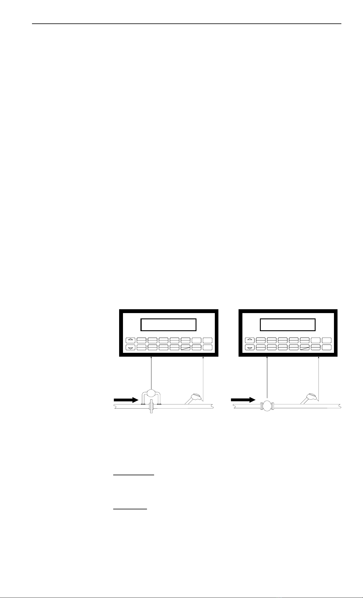
3.3 Liquid Mass
Measurements:
Actual volume is measured by the flow element (DP transmitter,
Flowmeter). Temperature is measured by the temperature transmitter. A
density transmitter can be used for direct density measurements.
Calculations:
• The density and mass flow are calculated using the reference density
and the thermal expansion coefficient of the liquid (see "SET FLUID
PROPERTIES" submenu)
Output Results:
• Display Results
Flow Rate, Resettable Total, Non-Resettable Total, Temperature,
Density
• Analog Output
Rate, Total, Temperature or Density
• Pulse Output
Total
• Relay Outputs
Rate, Total or Temperature Alarms
Applications:
Monitoring mass flow and total of any liquid. Flow alarms are provided via
relays and datalogging is available via analog (4-20mA) and serial outputs.
Liquid Mass
Liquid Mass
Illustration
Volume Flow
As calculated in section 3.1
Mass Flow
Mass Flow = volume flow * density
Calculations
STOP
START PRINT
5
0–
TIME
CLEAR
•
MENU
ENTER
HELP
TEMP
4
PRE 1
3
RATE
2
TOTAL
1
GRAND
6SCROLL
7PRE 2
8DENS
9
Orifice Plate
with DP Transmitter Temp./Dens.
Transmitter
STOP
START PRINT
5
0–
TIME
CLEAR
•
MENU
ENTER
HELP
TEMP
4
PRE 1
3
RATE
2
TOTAL
1
GRAND
6SCROLL
7PRE 2
8DENS
9
Flowmeter Temp./Dens.
Transmitter

10
9200B Flow Computer
3.4 Batching
Measurements:
A flowmeter measures the actual volume in a liquid line. A temperature
sensor can also be installed to correct for liquid thermal expansion (see
3.2 Corrected Volume).
Calculations:
• For Flowmeters with Pulse Outputs, Volume flow is calculated using
the flowmeter frequency output and the user entered K-Factor.
• For Flowmeters with Analog Transmitters, Volume flow is calculated
using the measured flowmeter signal and the user entered scale settings.
• Corrected Volume is calculated using the flow and temperature inputs
as well as the thermal expansion coefficient stored in the flow computer.
Output Results:
• Display Results
Flow Rate, Batch Total, Non-Resettable Total, Temperature, Density
• Analog Output
Rate, Total, Temperature or Density
• Pulse Output
Total
• Relay Outputs
Batch Total, Rate, or Temperature Alarms
Applications:
Batching and monitoring flow and total of any liquid. Batching is
accomplished via relays and datalogging is available via analog (4-
20mA) and serial outputs.
Batching
Batching Illustration
Calculations
Volume Flow
As calculated in section 3.1
Corrected Volume Flow
(Temp. Transmitter)
Corrected Vol. Flow = volume flow * (1 - Therm.Exp.Coef. *(Tf-Tref))2
STOP
START PRINT
5
0–
TIME
CLEAR
•
MENU
ENTER
HELP
TEMP
4
PRE 1
3
RATE
2
TOTAL
1
GRAND
6SCROLL
7PRE 2
8DENS
9
Flowmeter Temperature Transmitter
(Optional) Solenoid Valve

11
9200B Flow Computer
4 WIRING
4.1 Typical Wiring:
Typical Wiring
115 VAC
123456
Remote Counter
100 Ohm
DIN RTD
{
{
Alarm Relay 1
Alarm Relay 2
STRIPCHART
RECORDER
-
+
(+) Excitation
Signal Common
FLOW SENSOR
13 PULSE OUTPUT +
PULSE OUTPUT -
ANALOG OUTPUT -
ANALOG OUTPUT +
RLY1
RLY2
AC LINE
AC NEUTRAL24
18 COM
19
20
21
22
23
NO
NC
COM
NO
14
15
16
17 NC
POWER IN
4-20 mA
COM RLY3
COM RLY4
26
27
28
29
30
NO
NC
NO
25 NC
PULSE IN 1
PULSE IN 2
DC OUTPUT
COMMON
RTD EXCIT +
RTD SENS
RTD SENS -
CNTR IN 1
CNTR IN 2
CNTR IN 3
COMMON
---------
8
9
10
11
12
2
3
4
5
6
7
1
SEE USER
MANUAL
COMP
Iin +
+
Vin +
Iin +
Vin +
IN
IN
FLOW
AC LINE
AC NEUTRAL34
31
32
33
DC +
DC - Auxiliary
Power Supply
24 VDC at
600 mA peak
115 VAC
(-) Excitation

12
9200B Flow Computer
5. UNIT OPERATION
5.1 Front Panel Operation Concept for Run Mode
The 9200B Flow Computer is fully programmable through the front panel.
Please review the following usage summary before attempting to use the
instrument.
HELP
On-line help is provided to assist the operator in using this product. The help is
available during RUN and SETUP modes simply by pressing the HELP key. The
HELP key is used to enter decimals when entering numeric values.
FUNCTION KEYS
In the RUN mode, several keys have a special, direct access feature, to display
an item of interest (i.e. RATE, TOTAL, PRE 1, etc.). Press the key to view your
choice. Press the SCROLL key to return to scrolling display.
CLEARING TOTALIZER
To clear the total, you must press the TOTAL Function Key 3 times. You will be
asked to verify this action. The operator will be prompted to enter password if the
unit is locked.
NOTE: In the Batcher Mode, simply press the CLEAR key to reset the total (the
batcher must be stopped or finished batching). It is not necessary to press
the TOTAL Function Key first.
CLEARING GRAND TOTAL
To clear the grand total, you must press the GRAND Function Key 3 times. You
will be asked to verify this action. The supervisor will be prompted to enter the
supervisor password if the unit is locked.
PRESET KEYS
In the RUN mode, PRE 1 & PRE 2 keys are used to view and/or change the preset
setpoints. To view the Presets, simply press the desired Preset key. Rapidly
press the Preset keys 3 times, then press the Clear key for direct editing of the
preset setpoints.
SCROLL
Rapidly press the Scroll key three times to setup a display list.
Press the CLEAR key to remove old scroll list.
Press the function key for the item you wish to add
Use the ∆ ∇ keys to assign the line.
PRINT
The PRINT key is used to print on demand. When the PRINT key is pressed, a
user defined list of data (TOTAL, RATE, PRE 1, etc.) is sent to the RS-232 port. A
timed message of "PRINTING" will be displayed to acknowledge the print request.
SPECIAL BATCHING KEYS
The START and STOP keys are used only when batching to start and stop
batches. The CLEAR key will clear the total without first pressing the TOTAL key
(unit must be stopped). All other keys work the same in both Rate/Total mode and
Batch mode. The Start and Stop keys operation are set by the control input
settings. The Start options are: START or RESET/START. The Stop options are:
STOP or STOP/RESET.
MENU KEY
The MENU key is used to enter the Setup and Test modes. Press the MENU key
to enter the Setup and Test modes. (See section 6 for Setup mode, section 8 for
Test mode). The MENU key is used as "escape" in Setup and Test Programming.
Pressing the MENU key wile programming in the Sub-Menu groups will backup the
display to that Sub-Menu group heading. Pressing the MENU key while viewing
the Sub-Menu groups will backup the display to the Top Level Menu.
ACKNOWLEDGING ALARMS
Most alarm messages are self-clearing. Press the ENTER key to acknowledge
and clear alarms.
NOTE: Some keys and functions are password protected. Enter the password to
gain access. The passwords are factory set as follows:
Operator = 0
Supervisor = 2000
How To Use
On-Line Help
How To Use
Function Keys
How To Clear The
Totalizer
How To Clear The
Grand Total
How To Enter
Presets
How To Create a
Scroll List
How To Use
The Print Key
How To Use
Special Batching
Keys
How To Use
The Menu Key
How To
Acknowledge Alarms
STOP
START PRINT
5
0–
TIME
CLEAR
•
MENU
ENTER
HELP
TEMP
4
PRE 1
3
RATE
2
TOTAL
1
GRAND
6SCROLL
7PRE 2
8DENS
9

13
9200B Flow Computer
5.2 General Operation
The unit can display: Rate, Total, Grand Total, Temperature, Density, Presets
and Time of Day. The Temperature and/or Density can be displayed even if
you are using the Volumetric Flow Equation (a Temperature or Density sensor
must be installed). When used with volumetric flowmeters, the unit can perform
Mass or Corrected Volume equations using a temperature or density sensor
(these equations can be computed without Temp/Dens sensors by using user
defined default values). The unit can be programmed to perform Ratemeter/
Totalizer or Batching functions (see section 6.3, SELECT INSTRUMENT
Submenu).
5.3 Ratemeter/Totalizer Operation
The Ratemeter/Totalizer mode is used primarily to monitor flowrate and
accumulated total. The relays can be used to trigger flow, total, temperature or
density alarms.
5.3.1 Password Protection for Rate/Total mode
After an Operator and/or Supervisor Password is entered in the setup mode
(see section 6.3, SETUP PASSWORD submenu), the unit will be locked. The
unit will prompt the user for the password when trying to perform the following
functions:
Clear Total
Clear Grand Total
Enter Menu
Edit Preset 1 (PRE 1 Key)
Edit Preset 2 (PRE 2 Key)
The Supervisor password should be reserved for supervisors. The Supervisor
password will allow access to restricted areas of the Setup and Test menus.
5.3.2 Relay Operation in Rate/Total mode
Up to four relays are available (two standard) for alarm outputs. The relays can
be assigned to trip according to rate, total, temperature, density readings or
general system alarms. The relays can be programmed for low or high alarms.
Preset 1 (RLY1) and Preset 2 (RLY2) are easily accessible by pressing the
PRE 1 or PRE 2 key on the front panel. Preset 3 and Preset 4 are accessible
only through the setup menu.
5.3.3 Pulse Output in Rate/Total mode
The isolated pulse output (open collector) is menu assignable to Volume Total,
Corrected Volume Total or Mass Total. The pulse output duration can be set for
10mS (50 Hz max) or 100mS (5 Hz max). A pulse output scale factor (pulse
value) can be set to scale the pulse output. The pulse output is ideal for
connecting to remote totalizers or other devices such as a PLC. See section
1.3 for electrical specifications.
5.3.4 Analog Output in Rate/Total mode
The analog output is menu assignable to correspond to the Volume Rate,
Corrected Volume Rate, Mass Rate, Temperature, Density, Volume Total,
Corrected Volume Total or Mass Total. The analog output is ideal for "trend"
tracking using strip chart recorders or other devices.
General
Operation
Rate/Total
Operation
Password Protection
(Rate/Total mode)
Relay Operation
(Rate/Total mode)
Pulse Output
(Rate/Total mode)
Analog Output
(Rate/Total mode)

14
9200B Flow Computer
5.3.5 RS-232 Serial Port Operation in Rate/Total mode
The RS-232 serial port can be used for programming (using the Setup Disk)
or for communicating to printers and computers in the Operating Mode (Run
Mode).
PC Communications:
The Setup Disk also allows the user to query the unit for operating status
such as Flow Rate, Flow Total, Temperature, Density, Presets, etc.
Operation of RS-232 Serial Port with Printers:
Transaction Printing
For transaction printing, the user defines the items to be included in the
printed document (see section 6.3.20 SET DATA OUTPUT, Select_list). The
transaction document can be initiated by pressing the PRINT key or by a
remote contact closure.
Data Logging
In data logging, the user defines the items to be included in each data log
(see section 6.3.20 SET PRINTER OUTPUT, Select_list). The user can also
select when (time of day) or how often (print interval) the data log is to be
made (see section 6.3.19 SET PRINTER OUTPUT, Configure).
System Setup and Maintenance Report
The system setup and maintenance report lists all of the instrument setup
parameters and usage for the current instrument configuration. The audit
trail information and a status report is also printed. This report is initiated in
the Test menu (see section 8.2.3 PRINT SYSTEM SETUP).
RS-232 Serial Port
(Rate/Total mode)
5.3.6 RS-485 Serial Port (optional)
RS-485 Port Description:
The optional RS-485 card utilizes Modbus RTU protocol to access
a variety of process parameters and totalizers. The Relays can
be controlled via Modbus. In addition, action routines can be
executed. For further information, contact factory and request
RS-485 Protocol manual.
Operation of Serial Communication Port with PC
The flow computer's RS-485 channel supports a number of
Modbus RTU commands. Modbus RTU drivers are available
from third party sources for a variety of Man Machine Interface
software for IBM compatible PC's.
The user reads and writes information from/to the RS-485 using
the Modbus RTU commands. The 9200B Flow Computer then
responds to these information and command requests.
Process variables and totalizers are read in register pairs in
floating point format. Time and date are read as a series of
integer register values. Alarms are individually read as coils.
Action routines are initiated by writing to coils.
RS-485 Serial Port
(Rate/Total mode)

15
9200B Flow Computer
5.4 Batcher Operation
The Batcher mode is used primarily to control batches. The main difference
between the Batch mode and Rate/Total mode is the relay operation. The
Batch mode allows the operator to "START" the unit via the front panel or
remote input. Once started, the relays (RLY1 & RLY2) will energize and send
power to a flow control device (i.e. solenoid valve or pump). The flow sensor
will send a signal to the unit and total accumulation will begin. When the
Prewarn value (PRE 2) is reached, Relay 2 will drop out (this is ideal for flow
slow down). When the Batch amount (PRE 1) is reached, Relay 1 will drop out
and the Batch is complete.
Several messages will be displayed during normal batch operation (i.e. Batch
Fill, Batch Stopped). The keypad is disabled for the duration of these timed
messages (approx. 2 sec).
5.4.1 Batcher Configuration.
When the unit is programmed for batch mode, several batch operation choices
are available. These choices include: Up or Down Counting, Maximum Batch
Preset, Batch Overrun Compensation, Auto Batch Restart, Time Delay, Start or
Reset/Start, and Stop or Stop/Reset.
Batch Count Mode
The Batch Count Mode allows the user to choose whether the unit will batch up
to a preset value or batch down from a preset value to zero.
Maximum Batch Preset
The Maximum Batch Preset allows the user to program the Maximum Batch
value allowed to be entered by the operator. If an operator should try to
program a batch higher then this value, the unit will not allow the value to be
entered and will prompt the user with an error message saying that the Maximum
Batch Preset has been exceeded.
Batch Overrun
The Batch Overrun is used for batch applications that have slow responding
valves and a consistent batching flowrate. When the Batch Overrun is set, the
unit will compensate for batch overruns by computing an averaged overrun
value from the last four batches. This average is used to internally adjust the
batch setpoint to minimize overrun.
Auto Batch Restart
The Auto Batch Restart function allows the user to set an amount of time to
automatically restart a batch after the completion of a batch. This time can be
set from 1 to 99 seconds.
Time Delay
The Time Delay for Auto Batch Restart functions as follows: When a batch is
completed, the next batch will automatically start after the amount of time
entered here.
Batcher Configuration

16
9200B Flow Computer
START, RESET/START and STOP, STOP/RESET
When configuring the control inputs, Control Input1 can be set for START or
RESET/START. When set for START, the unit will start batching when a signal
is applied to Control Input1 or the front panel Start key is pressed. A separate
Reset signal must be used to clear the previous batch total. When set for
RESET/START, the unit will automatically reset then start when a signal is
applied to Control Input1 or the front panel Start key is pressed (provided that
the pervious batch was completed). If a previous batch was stopped during a
batch cycle, the unit will Start from where it was stopped.
Control Input 2 can be set for STOP or STOP/RESET. When set for STOP, the
unit will stop batching when a signal is applied to Control Input 2 or the front
panel Stop key is pressed. A separate Reset signal must be used to clear the
batch total. When set for STOP/RESET, a running batch will stop when a
signal is applied to Control Input 2 or the front panel Stop key is pressed. If the
unit is Stopped or after a completed batch, the unit will reset when a signal is
applied to Control Input 2 or the front panel Stop key is pressed.
NOTE: Applying a voltage level to Control Input 2 will inhibit all Start inputs in
either mode.
5.4.2 Password Protection for Batcher Mode
After an Operator and/or Supervisor Password is entered in the setup mode
(see section 6.3, SETUP PASSWORD submenu), the unit will be locked. The
unit will prompt the user for the password when trying to perform the following
functions:
Clear Grand Total
Enter Menu
The Supervisor password should be reserved for supervisors. The Supervisor
password will allow access to restricted areas of the Setup and Test menus.
The passwords are factory set as follows:
Operator = 0
Supervisor = 2000
5.4.3 Relay Operation in Batcher mode
Up to four relays are available (two standard) for alarm outputs. Preset 1
(RLY1) is reserved for batch amount, Preset 2 (RLY2) is reserved for prewarn.
(see section 5.4 Batcher Operation for Relay 1 & Relay 2 functions)
Preset 1 (RLY1) and Preset 2 (RLY2) are easily accessible by pressing the PRE
1 or PRE 2 key on the front panel. Preset 3 and Preset 4 are accessible only
through the setup menu.
Relays 3 and 4 can be assigned to trip according to rate, total, temperature,
overrun or alarm. When Rate is selected the relays can be programmed for low
or high alarms.
5.4.4 Pulse Output in Batcher mode
The isolated pulse output (open collector) is menu assignable to Volume Total,
Corrected Volume Total or Mass Total. The pulse output duration can be set for
10mS (50 Hz max) or 100mS (5 Hz max). A pulse output scale factor (pulse
value) can be set to scale the pulse output. The pulse output is ideal for
connecting to remote totalizers or other devices such as a PLC. See section 1.3
for electrical specifications.
5.4.5 Analog Output in Batcher mode
The analog output is menu assignable to correspond to the Volume Rate,
Corrected Volume Rate, Mass Rate, Temperature, Density, Volume Total,
Corrected Volume Total or Mass Total. The analog output is ideal for "trend"
tracking using strip chart recorders or other devices.
Password Protection
(Batch mode)
Relay Operation
(Batch mode)
Pulse Output
(Batch mode)
Analog Output
(Batch mode)
Table of contents
Popular Desktop manuals by other brands


Crestron
Crestron EDU-500 quick start

IBM
IBM NetVista Hardware Maintenance Manual

Lenovo
Lenovo ThinkCentre M72z Handboek voor de gebruiker

Lenovo
Lenovo ThinkCentre A51p Hardware removal and replacement guide

Moxa Technologies
Moxa Technologies DA-680 Series Quick installation guide

IBM
IBM 8862 - Eserver xSeries 365 Maintenance and troubleshooting guide