Thermal Solutions EVAW Series Service manual

1
Price - $3.00
INSTALLATION, OPERATING AND
SERVICE INSTRUCTIONS
EVAW SERIES WATER HEATER
102462-01-12/12
Your Local Thermal Solutions Representative:
ON/OFF, MODULATION
For Service and repairs to the heating plant, call your heating contractor. When seeking information on the water
heater from the manufacturer, provide water heater model and serial number as shown on rating label.
Water Heater Model
Serial Number Type System
Heating Contractor
EVAW-
Phone NumberAddress
Installation Date
AS
ME
H
File Number
MH47005

2
The following terms are used throughout this manual to bring attention to the presence of hazards of various risk
levels, or to important information concerning product life.
IMPORTANT INFORMATION - READ CAREFULLY
NOTE: Post these instructions and maintain in legible condition.
NOTE: The equipment shall be installed in accordance with those installation regulations required in the area
where the installation is to be made. These regulations shall be carefully followed in all cases. Authorities having
jurisdiction shall be consulted before installations are made.
All wiring on W. H. installed in the USA shall be in accordance with the National Electrical Code and/or local
regulations.
All wiring on W. H. installed in Canada shall be in accordance with the Canadian Electrical Code and/or local
regulations.
AVERTISSEMENT. Assurez-vous de bien suivre les
instructions données dans cette notice pour réduire au
minimum le risque d'incendie ou d'explosion ou pour
éviter tout dommage matériel, toute blessure ou la
mort.
- Ne pas entreposer ni utiliser d'essence ou ni d'autres
vapeurs ou liquides inammables à proximité de cet
appareil ou de tout autre appareil.
- QUE FAIRE SI VOUS SENTEZ UNE ODEUR DE GAZ:
• Ne pas tenter d'allumer d'appareil.
• Ne touchez à aucun interrupteur; ne pas vous servir
des téléphones se trouvant dans le bâtiment.
• Appelez immédiatement votre fournisseur de gaz
depuis un voisin. Suivez les instructions du
fournisseur.
• Si vous ne pouvez rejoindre le fournisseur, appelez
le service des incendies.
- L'installation et l'entretien doivent être assurés par un
installateur ou un service d'entretien qualié ou par le
fournisseur de gaz.
DANGER
Indicates an imminently hazardous situation
which, if not avoided, will result in death, serious
injury or substantial property damage.
WARNING
Indicates a potentially hazardous situation which,
if not avoided could result in death, serious injury
or substantial property damage.
CAUTION
Indicates a potentially hazardous situation which,
if not avoided could result in death, serious injury
or substantial property damage.
NOTICE
Indicates special instructions on installation,
operation, or maintenance which are important
but not related to personal injury hazards.
WARNING: If the information in theses instructions
is not followed exactly, a re or explosion may result
causing property damage, personal injury or death.
- Do not store or use gasoline or other ammable
vapors and liquids in the vicinity of this or any other
appliance.
- WHAT TO DO IF YOU SMELL GAS
• Do not try to light any appliance.
• Do not touch any electrical switch; do not use any
phone in your building.
• Immediately call your gas supplier from a neighbor's
phone. Follow the gas suppliers instructions.
• If you cannot reach your gas supplier, call the re
department.
- Installation and service must be performed by a
qualied installer, service agency or the gas supplier.

3
ECITON
.launamsihtfokcabehtnodetnirpsihcihwfoypoca,ytnarrawdetimilasahreliobsihT
dellatsniyltcerroceraslortnocllatahteesotrotcartnocgnillatsniehtfoytilibisnopserehtsitI
.etelpmocsinoitallatsniehtnehwylreporpgnitarepoeradna
This water heater has a limited warranty, a copy of which is printed on the back of this manual. It is the
responsbility of the installing contractor to see that all controls are correctly installed and are operating
properly when the installation is complete.
NOTICE
This water heater requires regular maintenance and service to operate safely. Follow the instructions
contained in this manual.
Improper installation, adjustment, alteration, service or maintenance can cause property damage, personal
injury or loss of life. Read and understand the entire manual before attempting installation, start-up,
operation, or service. Installation and service must be performed only by an experienced, skilled installer or
service agency.
The water heater must be properly vented.
This water heater needs fresh air for safe operation and must be installed so there are provisions for
adequate combustion and ventilation air.
The interior of the venting and air intake systems must be inspected and cleaned annually and should be
inspected periodically for any obstructions. Clean and unobstructed venting and air intake systems are
necessary to allow noxious fumes that cause injury or loss of life to vent safely and will contribute toward
maintaining the water heater's efciency.
Installation is not complete unless a factory supplied pressure relief valve is installed on the water heater
- see Installation section of this manual for details.
This water heater is supplied with safety devices which may cause the appliance to shut down and not
re-start without service - if damage due to frozen pipes is a possibility, the domestic hot water system
should not be left unattended in cold weather; or appropriate safeguards and alarms should be installed on
the system to prevent damage if the water heater is inoperative.
This water heater contains very hot water under high pressure. Do not unscrew any pipe ttings nor
attempt to disconnect any components of this water heater without positively assuring the water is cool
and has no pressure. Always wear protective clothing and equipment when installing, starting up or
servicing this water heater to prevent scald injuries. Do not rely on the pressure and temperature gauges
to determine the temperature and pressure of the water heater. This water heater contains components
which become very hot when the water heater is operating. Do not touch any components unless they are
cool.
Water heater materials of construction, products of combustion and fuel contain alumina, silica, heavy
metals, carbon monoxide, nitrogen oxides, aldehydes and/or other toxic or harmful substances which can
cause death or serious injury and which are known to the state of California to cause cancer, birth defects
and other reproductive harm. Always use proper safety clothing, respirators and equipment when servicing
or working nearby the appliance.
Failure to follow all instructions in the proper order can cause personal injury or death. Read all
instructions, including all those contained in component manufacturers manuals which are provided with
the water heater before installing, starting up, operating, maintaining or servicing.
Keep water heater area clear and free from combustible materials, gasoline and other ammable vapors or
liquids.
All cover plates, enclosures and guards must be in place at all times.
This product must be installed by a licensed plumber or gas tter when installed within the Commonwealth
of Massachusetts.
WARNING

4
I. Pre-Installation................................. 6
II. Unpacking the Water Heater .......... 8
III. Installation........................................ 9
A. Vent Guidelines Due to Removal
of an Existing Water Heater.........9
B. Venting ........................................ 9
C. Combustion Air ......................... 16
D. Water Treatment ....................... 18
E. Water Piping and Trim .............. 19
F. Gas Piping ................................ 22
G. Electrical ................................... 26
Table of Contents
Minimum Clearance to Combustible Materials
Left Side Right Side Front Rear Top Flue Connector
6" 6" 24" 6" 6" 18"
*Recommended Clearance for Service*
Left Side or Right Side Front Rear______ Top
500 24" 24" 24" 16"
750 24" 24" 24" 16"
1000 24" 24" 24" 16"
1500 24" 24" 24" 19"
2000 24" 24" 24" 31"
* When 3 or more units are mounted side-by-side, front service clearance increases by 12"
and the rear service clearance increases by 24".
NOTE: Verify clearance with local codes.
H. Modular Systems ...................... 29
I. Condensate Drains ................... 34
IV. System Start-up ............................. 36
V. Operation ....................................... 39
VI. Service/Maintenance ..................... 43
VII. Repair Parts .................................. 52
VII. Appendix A. Temperature
Controller Operation for
Modulating Water Heaters ............. 69
NOTICE
Modular systems (two or more EVA Series water heaters) may be installed with zero (0) side clearances
between the water heaters.

5
Figure 1: Dimensions and Capacities
WATER
HEATER
DIMENSION
A B C E F G H J K L M N P Q R S T U V W X Y Z
EVA-500 71-1/4 28-1/4 30-1/4 41-1/8 17-1/8 6-1/8 4-1/8 21-3/4 14-1/2 11-1/4 2 1-1/4 4 4 5-1/2 14-1/8 23-5/8 13-1/4 3-1/2 19-1/2 9-1/4 6-1/4 16
EVA-750 61 28-1/4 30-1/4 30-5/8 17-7/8 7 4-3/8 21-3/4 14-1/2 19 3 1-1/2 4 6 6-1/8 13-7/8 23-5/8 9-1/2 3-1/2 19-1/2 9-1/4 6-1/4 16
EVA-1000 67-1/8 28-1/4 30-1/4 36-3/4 17-7/8 7 4-3/8 21-3/4 14-1/2 19 3 1-1/2 6 6 6-1/8 13-7/8 23-5/8 9-1/2 3-1/2 19-1/2 9-1/4 6-1/4 16
EVA-1500 79-1/8 28-1/4 30-1/4 49 17-7/8 7 4-3/8 21-3/4 27-1/2 19 3 1-1/2 6 8 6-1/8 13-7/8 23-5/8 9-1/2 3-1/2 19-1/2 9-1/4 6-1/4 19
EVA-2000 91-3/4 28-1/4 30-1/4 61-3/8 17-7/8 7 4-3/8 21-3/4 27-1/2 19 3 1-1/2 6 8 6-1/8 13-7/8 23-5/8 9-1/2 9-1/4 19-1/2 9-1/4 6-1/4 31
ELECTRICAL
WATER
HEATER
MODEL
RANGE
MOTOR
(HP)
STANDARD
ELECTRICAL SUPPLY
(VOLTS/HERTZ/PHASES)
TOTAL CURRENT
DRAW
ON/OFF
(AMPS)
MOD
(AMPS)
500 1/2
120/60/1 8.1 2.50
208/60/1 4.4 2.52
230/60/1 4.4 2.52
230/60/3 2.6 2.52
230/60/3 2.52 2.52
460/60/3 1.61 1.61
750/2000 1-1/2
120/60/1 17.7 4.96
208/60/1 9.2 4.96
230/60/1 9.2 4.96
208/60/3 5.2 4.96
230/60/3 4.96 4.96
460/60/3 2.83 2.83
WATER
HEATER
MODEL
CAPACITIES
INPUT
(MBH)
OUTPUT
(MBH)
WATER
VOLUME
(GAL.)
HEAT
TRANSFER
AREA
(SQ.FT.)
DRY
WEIGHT
(LBS.)
WET
WEIGHT
EVA-500 500 410 6.1 123 817 868
EVA-750 750 615 15.9 131 1,172 1,305
EVA-1000 1,000 820 16.4 175 1,260 1,397
EVA-1500 1,500 1,230 17.4 264 1,402 1,547
EVA-2000 2,000 1,640 18.5 352 1,536 1,690
'H'
'L'
21
4
'U'
'G'
'S'
'E'
'F'
'K'
'R'
'W'
'A'
'B' 'C'
'V'
'Y'
'T'
'J'
'Z'
REQUIREMENT
FOR BURNER
REMOVAL 'X'
GAS PILOT
1/4 O.D. TUBE
GAS VENT
3/4 NPT PIPE
WATER
OUTLET
'M' NPT PIPE
INLET AIR
'Q' DIAMETER
GALVANIZED DUCT
CONDENSATE DRAIN
5/8 O.D. TUBE -
TO BE PIPED TO AN
EXTERNAL TRAP
BOILER DRAIN
1 NPT PIPE
GAS SUPPLY
'N' NPT PIPE
WATER INLET
'M' NPT PIPE
FLUE OUTLET
'P' DIAMETER
SAF-T-VENT
WATER HEATER DRAIN
1 NPT PIPE

6
WARNING
Adequate combustion and ventilation air must be
provided to assure proper combustion.
I. Pre-Installation
A.Installation must conform to the requirements of
the authority having jurisdiction. In the absence
of such requirements, installation must conform
to the National Fuel Gas Code, NFPA 54/ANSI
Z223.1, and/or CAN/CGA B149.1 Natural Gas
and Propane Installation Code. Where required
by the authority having jurisdiction, the installation
must conform to the Standard for Controls and
Safety Devices for Automatically Fired Boilers,
ANSI/ASME CSD-1.
B. Thewaterheaterisnotdesigncertiedfor
installationoncombustibleooring.Thewater
heater must not be installed on carpeting.
C. Provide clearance between water heater jacket
and combustible material in accordance with local
reordinance.Refertopage4ofthismanual
for minimum listed clearance from combustible
material.
D. Installonleveloor.Forbasementinstallation
provideconcretebaseifoorisnotperfectlylevel
orifwatermaybeencounteredonooraround
water heater. Floor must be able to support
weight of water heater, water and all additional
system components.
E. Protect gas ignition system components from
water (dripping, spraying, rain, etc.) during
water heater operation and service (circulator
replacement, condensate trap service, control
replacement, etc.).
F. Provide combustion and ventilation air in
accordance with applicable provisions of local
building codes or: USA - National Fuel Gas
Code, NFPA 54/ANSI Z223.1, Section 5.3, Air for
Combustion and Ventilation; Canada - Natural Gas
Installation Code, CAN/CGA - B149.1, or Propane
Installation Code, CAN/CGA - B.149.2, Part 5,
Venting Systems and Air Supply for Appliances.
G. Locate the water heater in an area where leakage
of the appliance or connections will not result in
damage to the area adjacent to the appliance or to
loweroorsofthestructure.Whensuchlocation
cannot be avoided it is recommended that a
suitable drain pan, adequately drained, be
installed under the appliance; however, the
panmustnotrestrictcombustionairow.
H. Provide adequate combustion and ventilation air
required for operation of the water heater. Refer
to the venting and combustion air sections of this
manualforspecicinstructions.
I. Provide adequate clearance for servicing and
proper operation.
J. For other than direct vent applications, the
appliance must be located as close as possible to
a chimney or gas vent.
The following guideline is based on the National Fuel
Gas Code, NFPA 54/ANSI Z223.1.
1. Determine volume of space (boiler room).
Rooms communicating directly with space
(through openings not furnished with doors) are
considered part of space.
Volume [ft³] = Length [ft] x Width [ft] x Height [ft]
2. Determine Total Input of all appliances in
space. Round result to nearest 1,000 Btu per
hour (Btuh).
3. Determine type of space. Divide Volume by
Total Input.
a. If result is greater than or equal to 50 ft³
per 1,000 Btuh, space is considered an
unconned space.
b. If result is less than 50 ft³ per 1,000 Btuh,
space is considered a conned space.
4. Determine building type. A building of
unusually tight construction has the following
characteristics:
a. Walls and ceiling exposed to outside
atmosphere have a continuous water vapor
retarder with a rating of 1 perm or less with
openings gasketed and sealed, and;
b. Weather-stripping has been added on
openable windows and doors, and;
c. Caulking or sealants applied in joints around
window and door frames, between sole
platesandoors,betweenwall-ceiling
joints, between wall panels, at plumbing
and electrical penetrations, and at other
openings.
WARNING
Carefully read all instructions before installing
water heater. Failure to follow all instructions in
proper order can cause personal injury or death.

7
6. For water heater located within unconned
space in building of unusually tight construction
or within conned space, provide outdoor
air through two permanent openings which
communicate directly or by duct with the
outdoors or spaces (crawl or attic) freely
communicating with the outdoors. Locate
one opening within 12 inches of top of space.
Locate remaining opening within 12 inches of
bottom of space. Minimum dimension of air
opening is 3 inches. Size each opening per the
following:
a. Direct communication with outdoors.
Minimum free area of 1 square inch per
4,000 Btu per hour input of all equipment in
space.
b. Vertical ducts. Minimum free area of 1
square inch per 4,000 Btu per hour input of
all equipment in space. Duct cross-sectional
area shall be same as opening free area.
c. Horizontal ducts. Minimum free area of 1
square inch per 2,000 Btu per hour input of
all equipment in space. Duct cross-sectional
area shall be same as opening free area.
Alternate method for water heaters located
withinconnedspace.Useindoorairiftwo
permanent openings communicate directly
withadditionalspace(s)ofsufcientvolume
such that combined volume of all spaces
meetcriteriaforunconnedspace.Sizeeach
opening for minimum free area of 1 square inch
per 1,000 Btu per hour input of all equipment in
spaces, but not less than 100 square inches.
7. Ventilation Duct Louvers and Grilles. Equip
outside openings with louvers to prevent
entrance of rain and snow, and screens to
prevent entrance of insects and rodents.
Louversandgrillesmustbexedinopen
position or interlocked with equipment to open
automatically before burner operation. Screens
must not be smaller than ¼ inch mesh.
Consider the blocking effect of louvers, grilles
and screens when calculating the opening size
to provide the required free area. If free area
of louver or grille is not known, assume wood
louvers have 20-25 percent free area and metal
louvers and grilles have 60-75 percent free
area.
Water heaters operated with sealed combustion
are exempt from needing provisions for
combustion air from the room, provided air
intake piping is installed per code and the
instructions in this manual.
NOTICE
REGNAD
rehtoroenilosagerehwreliobllatsnitonoD
fosecruosro,sdiuqilrosropavelbammalf
,srenaelc,sehcaelb.e.i(snobracordyh
cirbaf,srevomertniap,syarps,slacimehc
.derotsrodesuera).cte,srenetfos
Do not install water heater where gasoline or
other ammable vapors or liquids, or sources of
hydrocarbons (i.e. bleaches, cleaners, chemicals,
sprays, paint removers, fabric softeners, etc.) are
used or stored.
DANGER
ECITON
,reliobehtfotnetnocretawwolehtoteuD
otdragerhtiwreliobehtfognizistcerrocni
nitluserlliwdaolmetsysgnitaeheht
detareleccadnagnilcycreliobevissecxe
snoituloSlamrehT.eruliaftnenopmoc
ybdesuacseruliaftnarrawTONSEOD
OD.snoitacilppareliobdezisyltcerrocni
.metsysehtotreliobehtezisrevoTON
ehtecuderyltaergsreliobraludoM
.gnizisrevoreliobfodoohilekil
Due to the low water content of the water heater,
incorrect sizing of the water heater with regard
to the heating system load will result in
excessive cycling and accelerated component
failure. Thermal Solutions DOES NOT warrant
failures caused by incorrectly sized water heater
applications. DO NOT oversize the water heater
to the system. Modular water heaters greatly
reduce the likelihood of oversizing.
NOTICE
5. For water heater located in an unconned
space in a building of other than unusually
tight construction, adequate combustion and
ventilation air is normally provided by fresh air
inltrationthroughcracksaroundwindowsand
doors.

8
II. Unpacking the Water Heater
E. Tilt the water heater to one side and slide a small
roller under the raised base.
F. Tilt the water heater to the other side and slide
another roller under the base.
Placealargerpiperolleronoorbehindtheskid.
G. Roll the water heater forward or backward off the
skid and onto the pipe roller.
H. Move water heater to its permanent location.
A.Move water heater to approximate installed
position.
B. Remove all crate fasteners.
C. Open outside container and remove all inside
protective spacers and bracing.
D. Remove all appliance hold-down fasteners.
CAUTION
Do not drop water heater. Do not bump water
heater jacket against oor.
WARNING
Installation of this water heater should be under-
taken only by trained and skilled personnel from
a qualied service agency.
ECITON
,reliobehtfotnetnocretawwolehtoteuD
otdragerhtiwreliobehtfognizistcerrocni
nitluserlliwdaolmetsysgnitaeheht
detareleccadnagnilcycreliobevissecxe
snoituloSlamrehT.eruliaftnenopmoc
ybdesuacseruliaftnarrawTONSEOD
OD.snoitacilppareliobdezisyltcerrocni
.metsysehtotreliobehtezisrevoTON
ehtecuderyltaergsreliobraludoM
.gnizisrevoreliobfodoohilekil
NOTICE
Water heater crate is equipped with a tip & tell
label. If label indicates water heater has been
tipped over during shipping, remove crate and
inspect before trucker leaves.

9
III. Installation
A. VENT GUIDELINES DUE TO REMOVAL OF AN
EXISTING WATER HEATER
For installations not involving the replacment of an
existing water heater, proceed to step B.
When an existing water heater is removed from
a common venting system, the common venting
system is likely to be too large proper venting of the
remaining appliances. At the time of removal of an
existing water heater, the following steps shall be
followed with each appliance remaining connected
to the common venting sytem placed in operation,
while the other appliances remaining connected to
the common venting system are not in operation:
1. Seal any unused openings in the common venting
system.
2. Visually inspect the venting system for proper size and
horizontal pitch and determine there is no blockage or
restriction,leakage,corrosion,andotherdeciencies
which could cause an unsafe condition.
3. Insofar as is practical, close all building doors and
windows and all doors between the space in which
the appliances remaining connected to the common
venting system are located and other spaces of the
building. Turn on clothes dryers and any appliance
not connected to the common ventings system.
Turn on any exhaust fans, such as range-hoods and
bathroom exhausts, so they will operate at maximum
speed. do not operate a summer exhaust fan. Close
replacedampers.
4. Place in operation the appliance being inspected.
Follow the Lighting (or Operating) Instructions.Adjust
thermostat so appliance will operate continuously.
5. Test for Spillage at the draft hood relief opening
afterve(5)minutesofmainburneroperation.Use
themaeofamatchorcandle,orsmokefroma
cigarette, cigar, or pipe.
6. After it has been determined that each appliance
remaining connected to the common venting system
properly vents when tested as outlined above, return
doors,windows,exhaustfants,replacedampers
and any other gas burning appliance to their previous
conditions of use.
7. Any improper operation of the common venting
system should be corrected so teh installation
conforms with the National Fuel Gas Code, NFPA
54/ANSI Z223.1. When resizing any portion of the
common venting system, the common venting
system should be resized to approach the minimum
size as determined using the appropriate tables in
Part II in the National Fuel Gas Code, NFPA54/ANSI
Z223.1.
B. VENTING
WARNING
Improper venting may result in property damage
and the release of ue gasses which contain
deadly carbon monoxide (CO) into the building,
which can cause severe personal injury and/or
death.
1. General Venting Requirements
In order to properly vent this water heater, the
installer must select and install a vent system that
meetsallrequirementsspeciedinthissection
(VENTING) as well as following the instructions
provided by the vent system manufacturer.
a. The vent system shall be designed and
constructed in accordance with the National Fuel
Gas Code/NFPA 54 ANSI Z223.1 and applicable
localbuildingcodestodevelopapositiveow
adequatetoconveyueorventgassestothe
outdoors.
b. If this water heater is being installed in
Massachusetts, follow the Massachusetts Code
instructions printed later in this section.
c. Consult the vent pipe manufacturer’s instructions
forventsystemassemblyandsystemspecic
installation requirements.
WARNING
Vent pipe system must be made of materials
approved for use with condensing ue gasses.
d. Vent pipe system shall be acceptable for use with
water heater fuel type.
e. Vent pipe system shall be compatible either by
directly connecting, or by use of an adapter, to the
water heater vent connection.
i. This boiler is shipped with an AL 29-4C® Heat-
Fab Saf-T-Vent connection.
ii. Alteration of the water heater vent connection
is prohibited.
f. Do not reduce the diameter of the vent pipe.
The vent pipe must not be smaller than the vent
connector on the water heater.

10
g. Vent pipe system must be adequately supported
atintervalsnolessthanve(5)feetapart.The
completed vent system must be rigid and able to
withstand impacts without collapse.
h. If any point of the vent pipe system is higher
thanthewaterheateruecollar,theventsystem
must have adequate condensate drain loop(s) to
prevent condensate from running back into the
water heater.
i. It is permissible to run vent pipe through a vertical
or horizontal chase provided minimum clearances
to combustible materials are maintained.
j. The minimum clearance to combustible material
issix(6)inches,unlessotherwisespeciedbythe
vent system manufacturer.
k. Horizontal vent pipe must slope no less than one
(1) inch in four (4) feet of run.
l. The vent termination location is restricted as
follows:
i. Minimum twelve (12) inches above grade plus
normally expected snow accumulation or seven
(7) feet above grade if located adjacent to public
walkways. DO NOT INSTALL over public walkway
where local experience indicates condensation or
vapor from the water heater creates a nuisance or
hazard.
ii. Minimum three (3) feet above any forced
air inlet located within ten (10) feet of the vent
termination.
iii. Minimum four (4) feet below, four (4) feet
horizontally or one (1) foot above any door,
window or gravity air inlet.
iv. Minimum four (4) feet horizontally from electric
meters, gas meters, regulators and relief valves.
This distance may be reduced if equipment is
protected from damage due to condensation or
vapor by enclosure, overhangs, etc.
v. Minimum twelve (12) inches from corners of
building.
m. Use appropriately designed thimbles when
passing through combustible walls or roofs.
n. Installre-stopswhereventpassesthrough
oors,ceilingsorframedwalls.There-stopmust
close the opening between the vent pipe and the
structure.
o. Enclose vent passing through occupied or
unoccupied spaces above the water heater with
materialshavingareresistanceratingatleast
equaltotheratingoftheadjoiningoororceiling.
Maintain minimum clearance to combustible
materials.
p. Locate vent terminal above combustion air intake
terminal (if used) and no closer than one (1) foot
horizontally.
q. Verticalventingrequiresashingandastorm
collar to prevent moisture from entering the
structure.
r. Vertical vent termination must be at least two (2)
feet plus the expected snow accumulation above
roof penetration height.
s. This water heater's venting may be Category
IV(positiveventpressure,uecondensing)or
CategoryII(non-positiveventpressure,ue
condensing), with regards to National Fuel Gas
Code/NFPA 54 ANSI Z223.1.
2. Positive Pressure Venting Requirements
a. Vent pipe system must be fully sealed.
WARNING
Do not use vent dampers or barometric dampers
with positive pressure vent systems.
b. Direct vent applications: For direct vent (ducted
combustion air) installations, the maximum vent
length is 50 equivalent feet. The vent length is
equal to the total length of straight pipe plus the
equivalentlengthofventttings.
c. Non-direct vent applications: For non-direct vent
installations (those without ducted combustion
air), design the vent system so that the pressure
measured at the outlet of the water heater is
between0”w.c.and0.3”w.c.athighre.
d. For sidewall venting, slope pipe toward vent
termination, if possible.
e. See Figures 2, 3 and 4 for examples of positive
pressure venting arrangements.
3. Negative Pressure (Conventional) Venting
Requirements
This section outlines requirements for conventional
venting installations, where a negative pressure at
thewaterheaterueoutletisachievedbymeans
of natural convection through a vertical length of
vent pipe or lined chimney.
a. Refer to Figure 5 for an example of a typical
conventional venting arrangement.
b. A lined chimney or vertical length of vent pipe may
be used. Chimney lining must be acceptable for
usewithcondensinguegas.

11
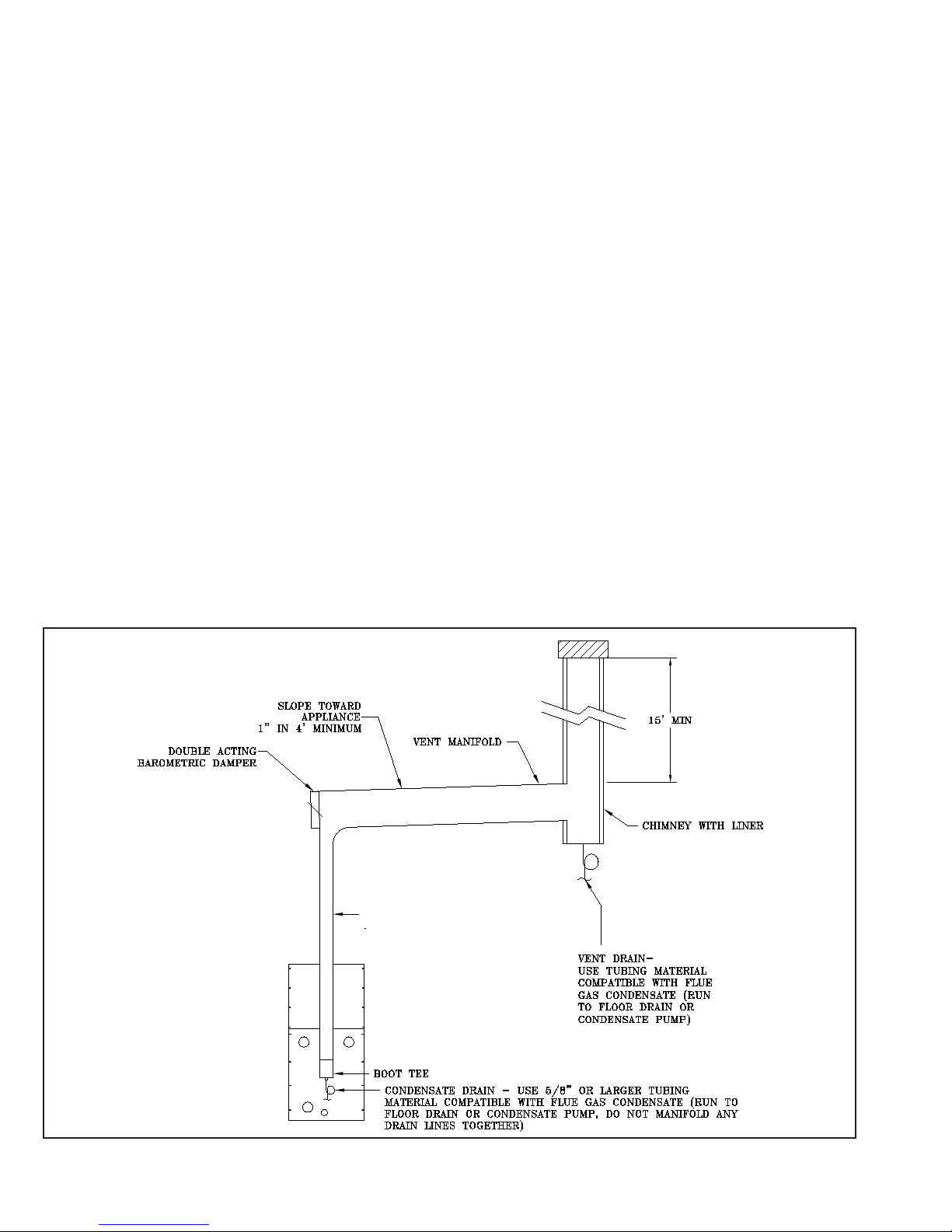
c. The minimum chimney/vertical vent height is 15
feet.
d. Install a condensate drain to collect any
condensate that may form in the lined chimney/
vertical vent.
e. Install a double acting barometric damper with
integraluespillageinterlock.
f. Thechimney/verticalventandueconnectormust
besizedandconguredtoprovideaminimum-0.04
inchw.c.pressure(draft)atthewaterheaterue
outlet.
g. The chimney must be protected from down drafts,
rain and debris by using a chimney cap or star.
h. Start installing vent at vent cap and continue
installation toward the water heater.
i. Theueconnectorandchimneyuediametermay
need to be increased or decreased depending on
the dimensions of the water heater. Consult the
National Fuel Gas Code or Local Codes for sizing.
Waterheaterinput,ueconnectorlateraldistance
andchimneyheightaffecttheueconnectoror
chimneyuediameters.
j. A double acting barometric damper with integral
uespillageinterlockswitchmustbeusedwhen
the water heater is vented conventionally.
4. General Guidelines
a. ThiswaterheaterhasbeencertiedwithAL29-
4C® venting. Select a vent material that is
approvedforusewithcondensinguegasses.
b. Install vent system before installing air intake,
water, gas or electrical connections.
c. For instances where the vent system
manufacturer’s instructions do not make a
specication,refertothebelowpoints.
i. Makesurepipeandttingsarecleanby
swabbing with alcohol. Use Dow Corning 736 or
732 RTV, Polybar #500 RTV or Sil-bond 4500 or
6500 to seal vent pipe.
ii. Refer to the appropriate drawings in this
section of this manual to determine common
acceptablecongurationsofventingsystem.
5. IMPORTANT
The Commonwealth of Massachusetts requires
compliance with regulation 248 CMR 4.00 and
5.00 for installation of side-wall vented gas
appliances as follows:
(a) For all side wall horizontally vented gas
fueled equipment installed in every dwelling,
building or structure used in whole or in part for
residential purposes, including those owned or
operated by the Commonwealth and where the
side wall exhaust vent termination is less than
seven(7)feetabovenishedgradeinthearea
of the venting, including but not limited to decks
and porches, the following requirements shall
besatised:
1. INSTALLATION OF CARBON MONOXIDE
DETECTORS. At the time of installation of
the side wall horizontal vented gas fueled
equipment,theinstallingplumberorgastter
shall observe that a hard wired carbon
monoxide detector with an alarm and battery
back-upisinstalledontheoorlevelwherethe
gas equipment is to be installed. In addition,
theinstallingplumberorgasttershallobserve
that a battery operated or hard wired carbon
monoxide detector with an alarm is installed on
each additional level of the dwelling, building
or structure served by the side wall horizontal
vented gas fueled equipment. It shall be the
responsibility of the property owner to secure
theservicesofqualiedlicensedprofessionals
for the installation of hard wired carbon
monoxide detectors.
a. In the event that the side wall
horizontally vented gas fueled equipment
is installed in a crawl space or an attic, the
hard wired carbon monoxide detector with
alarm and battery back-up may be installed
onthenextadjacentoorlevel.
b. In the event that the requirements of
this subdivision can not be met at the time
of completion of installation, the owner shall
have a period of thirty (30) days to comply
with the above requirements; provided,
however, that during said thirty (30) day
period, a battery operated carbon monoxide
detector with an alarm shall be installed.
2. APPROVED CARBON MONOXIDE
DETECTORS. Each carbon monoxide detector
as required in accordance with the above
provisions shall comply with NFPA 720 and be
ANSI/UL2034listedandIAScertied.
3. SIGNAGE.Ametalorplasticidentication
plate shall be permanently mounted to the
exterior of the building at a minimum height of
eight (8) feet above grade directly in line with
the exhaust vent terminal for the horizontally
vented gas fueled heating appliance or
equipment. The sign shall read, in print size
no less than one-half (1/2) inch in size, “GAS
VENT DIRECTLY BELOW. KEEP CLEAR OF
ALL OBSTRUCTIONS”.

12
2. Product Approved side wall horizontally
vented gas fueled equipment installed in a room
or structure separate from the dwelling, building
or structure
(c) MANUFACTURER REQUIREMENTS - GAS
EQUIPMENT VENTING SYSTEM PROVIDED.
When the manufacturer of Product Approved
side wall horizontally vented gas equipment
provides a venting system design or venting
system components with the equipment, the
instructions provided by the manufacturer for
installation of the equipment and the venting
system shall include:
4. INSPECTION. The state or local gas inspector
of the side wall horizontally vented gas fueled
equipment shall not approve the installation
unless, upon inspection, the inspector observes
carbon monoxide detectors and signage
installed in accordance with the provisions of
248 CMR 5.08(2)(a)1 through 4.
(b) EXEMPTIONS: The following equipment is
exempt from 248 CMR 5.08(2)(a)1 through 4:
1. The equipment listed in Chapter 10 entitled
“Equipment Not Required To Be Vented” in the
most current edition of NFPA 54 as adopted by
the Board; and
1. Detailed instructions for the installation of the
venting system design or the venting system
components; and
2. A complete parts list for the venting system
design or venting system.
(d) MANUFACTURER REQUIREMENTS - GAS
EQUIPMENT VENTING SYSTEM NOT
PROVIDED. When the manufacturer of a
Product Approved side wall horizontally
vented gas fueled equipment does not
providethepartsforventingtheuegases,
butidenties“specialventingsystems”,the
followingrequirementsshallbesatisedbythe
manufacturer:
1. The referenced “special venting system”
instructions shall be included with the appliance
or equipment installation instructions; and
2. The “special venting systems” shall be
Product Approved by the Board, and the
instructions for that system shall include a parts
list and detailed installation instructions.
(e) A copy of all installation instructions for all
Product Approved side wall horizontally vented
gas fueled equipment, all venting instructions,
all parts lists for venting instructions, and/or all
venting design instructions shall remain with
the appliance or equipment at the completion
of the installation.
Figure 5: Typical Negative Pressure (Conventional) Venting
VENT PIPE (SAME DIAMETER) AS
APPLIANCE VENT CONNECTOR

13
Figure 3: Sidewall Pressurized Venting (Optional)
Figure 2: Sidewall Pressurized Venting

14
Figure 4: Vertical Pressurized Venting

15
C. COMBUSTION AIR - See Figures 6 and 7.
1. The water heater may be operated with inside
or outside air.
2. Refer to combustion air piping drawings in this
section of this manual for proper outside air
installation details.
3. Combustion air conduit can be galvanized
smokepipe,PVC,CPVC,orexiblealuminum
conduit.
4. Themaximumairinletlengthisfty(50)
equivalent feet. Air inlet length is equal to the
total length of straight pipe plus the equivalent
lengthofttings.Consultconduitmanufacturer
forequivalentlengthofttingsandpipe.
5. Consult air intake pipe manufacturer's
instructions for proper method of sealing intake
pipesectionsandttings.Donotuseother
adhesives or sealants except as expressly
permitted by the intake pipe manufacturer's
instructions.
6. Air intake termination must be located at
least twelve (12) inches above grade plus the
expected snow accumulation.
7. Water heater may be installed with vertical
venting and sidewall combustion air inlet or
visa versa.
8. The air intake pipe must be adequately
supported with straps or supports no less
thanve(5)feetapart.Thecompletedair
intake pipe system must be rigid and able to
withstand impacts without collapse.
Dirty, contaminated or dusty air used for
combustion will decrease the useful life of the
water heater air lter. Use outside air if inside
air quality is questionable. Use outside air if the
water heater is installed in manufacturing plants,
laundries, dry cleaners or other locations with
heavy particulates in the air.
CAUTION
Do not locate air intake where petroleum
distillates, CFC's, detergents, volatile vapors or
any other chemicals are present. Severe water
heater corrosion and failure will result. Thermal
Solutions does not warrant failures caused by
contaminated air.
Do not locate air intake termination where
natural convection or wind conditions may
cause the water heater exhaust gases to be
drawn into the air intake.
WARNING
WARNING
Do not reduce size of air intake pipe.
Read, understand and follow combustion air
instruction restrictions contained in the
Pre-Installation instructions of this manual.
Figure 6: Horizontal Air Intake Piping

16
Figure 7: Vertical Air Intake Piping

17
D. WATER TREATMENT
The quality of water used in the system is essential for
the successful operation and longevity of the system
components. A successful water treatment plan will
helptomaintainefciency,reducetheregularityof
repair and/or replacement, and extend the working
life of the water heater and other system equipment.
If left untreated, poor water quality could cause a
number of problems including, but not limited to,
oxidation, scaling, corrosion, and fouling. See Table
0 for examples of typical chemical agents found in
untreated water along with their potential effects.
Table 0: Chemical Agents and Effects
Compound Effect
Calcium Carbonate
(CaCO3)
Soft Scale
Calcium Bicarbonate
(CaHCO3)
Soft Scale, CO2
Calcium Sulphate (CaSO4) Hard Scale
Calcium Choloride (CaCl2) Corrosion
Magnesium Carbonate
(MgCO3)
Soft Scale
Magnesium Bicarbonate
(MgHCO3)
Corrosion, Scale
Magnesium Sulphate
(MgSO4)
Corrosion
Silicon Dioxide (SiO2) Hard Scale
Since the condition of water varies from location
to location, it is impossible to prescribe a one-size-
ts-alltreatmentplanforthesystemwater.Inorder
to develop an effective water treatment plan, it will
be necessary to gain knowledge of the impurities
dissolved in the water. Once all the impurities
areidentied,thepropertreatmentplancanbe
established. Therefore, it will be essential to obtain
theexpertiseofaqualiedindustrialwatertreatment
professional for establishing a treatment plan.
In addition, a periodic testing/sampling plan should
be developed. The intent of the plan should be to: (1)
ensure the protection of the water heater and system
equipment, (2) prevent an unforeseen system failure,
(3) provide information for use in addressing the water
quality,and(4)toconrmtheproperconcentrationof
chemicals in use.
CAUTION
The system water shall have a maximum water
hardness of 8.5 grains or 150 ppm. However,
other aspects of water quality can affect system
operation and longevity. A qualied water
treatment expert should be consulted to develop
a complete water treatment plan.
Oxygen contamination of system water will
cause corrosion of iron and steel system
components, and can lead to failure. Thermal
Solutions Standard Warranty does not cover
problems caused by oxygen contamination of
system water.
Proper water treatment and water heater
maintenance is required to avoid scale build-
up on the inside of the water heater. Thermal
Solutions Standard Warranty does not cover
problems caused by scale build-up.

18
2. Design and install system piping to prevent
return water temperatures below 120°F. Refer
toTable1forwaterheaterowandpressure
drop requirements.
3. Connect system supply and return piping to
water heater. Refer to Figure 8. Also consult
I=B=R Installation and Piping Guides. Maintain
½" minimum distance between water piping
and combustible material. Consult Thermal
Solutions for unusual system requirements.
E. WATER PIPING AND TRIM
1. Design and install water heater and system
piping to prevent oxygen contamination of
appliance water and frequent water additions.
a. There are many possible causes of oxygen
contamination such as:
i. Addition of excessive make-up water
as a result of system leaks.
ii. Absorption through open tanks and
ttings.
iii. Oxygen permeable materials in the
distribution system.
b. In order to insure long product life, oxygen
sources must be eliminated. This can
be accomplished by taking the following
measures:
i. Repairing system leaks to eliminate the
need for addition of make-up water.
ii. Eliminatingand/orrepairingttings
which allow oxygen absorption.
iii. Using of non-permeable materials in the
distribution system.
iv. Isolating the water heater from the
system water by installing a heat
exchanger.
vi. Using properly designed and operating
air elimination devices in water piping. 4. Installdrainvalveinttingprovidedatbottom
rear of the water heater.
5. Install optional low water cut-off such as
McDonnell & Miller Model PS851-M-120 or
equal in system piping above the water heater.
Return water temperature below 120°F will cause
ue gas condensation inside the water heater.
Flue gas condensate can lead to water heater
failure. Thermal Solutions Standard Warranty
does not cover problems caused by ue gas
condensation. All piping either new or existing
must be cleaned to remove mill scale and oils
from the system. Failure to do so could result in
premature failure of the heat exchanger (not cov-
ered by Thermal Solutions Standard Warranty).
CAUTION
WARNING
Supply and return water temperature differences
greater than 40°F at high re can lead to water
heater failure. Thermal Solutions Standard
Warranty does not cover problems caused by
temperature difference greater than 40°F at high
re.
CAUTION
Failure to properly pipe water heater may result
in improper operation and damage to the water
heater structure.
On an existing or retrot system, a lter or
strainer must be installed on the system return
prior to the water heater.

19
6. Theremustbeaminimumofvepipe
diameters of straight horizontal run downstream
oftheowswitch.Otherwise,prematurefailure
ofowswitchpaddlemayoccur.Seeow
switch instruction manual (MM-601) included
with water heater.
7. If the water heater is installed in a closed water
supplysystem,suchasonehavingabackow
preventer in the cold water supply line,means
shall be provided to control thermal expansion.
Contact the water supplier or local plumbing
inspector on how best to control this situation.
8. A pressure relief valve is supplied with each
water heater. No valve is to be placed between
the relief valve and appliance. No reducing
coupling or other restriction shall be installed in
the discharge line.
a. Pipe the safety relief discharge to a
suitable place for disposal when relief
occurs.
b. Do not install reducing couplings or other
restrictive devices in the safety relief dis-
charge line.
c. The safety relief discharge line must allow
for complete drainage of both the value and
line.
9. If the relief valve discharges periodically, this
may be due to thermal expansion in a closed
water supply system. Contact the water
supplier or local plumbing inspector on how to
correct this situation. DO NOT PLUG THE
RELIEF VALVE.
10. The seperate hot water storage container must
have a temperature and pressure relief valve
installed.
a. This relief valve shall comply with the
standard for relief valves for hot water sup-
ply systems ANSI 221.22-CSA4.4.
Failure to operate the unit with the proper water
ow rate can lead to appliance failure. Always
install water ow switch so that the unit stops
operating if improper water ow is present.
Safety relief valve discharg piping must be piped
such that the potential of severe burns is
eliminated. DO NOT pipe in any area where
freezing could occur. DO NOT install any shut-off
valves, plugs or caps. Consult Local Codes for
proper discharge piping arrangement.
Do not operate water heater with ow rates in
excess of the maximum ow rates listed in Table
1. Tube erosion and pitting will occur. Thermal
Solutions Standard Warranty does not cover
problems caused by excessive water ow rates.
If a high head system pump is installed, assure
that the appliance relief valve and system piping
are capable of operating properly at the
combined pressure of the system ll pressure
plus the pump static head pressure.
Do not install valves, plgus or caps in safety
relief valve piping.
Do not install valves, plugs or caps in safety
relief valve piping.
Safety relief valve piping must be terminated
such that in the event the safety relief valve
opens, the discharge will not cause personal
injury or damage.
WARNING
TABLE 1 – EVA WATER HEATER FLOW AND PRESSURE DROP
WATER
HEATER
MODEL
20°ΔT
(at high re)
40°ΔT
(at high re) Minimum
Flow Rate
(GPM)
Maximum
Flow Rate
(GPM)
Supply/Return
Pipe
(inch dia.)
ΔP
(ft.)
Flow
(GPM)
ΔP
(ft.)
Flow
(GPM)
EVA-500 2.93 44 0.74 22 22 44 2
EVA-750 1.81 66 0.46 33 33 66 3
EVA-1000 3.24 88 0.81 44 44 88 3
EVA-1500 7.37 132 1.85 66 66 132 3
EVA-2000 13.27 176 3.32 88 88 176 3

20
b. No reducing coupling or other restriction
shall be installed in the discharge line.
c. No valve shall be placed between the
relief valve and tank.
11. The discharge from temperature and pressure
valve(s) shall be conducted to a suitable place
for disposal when relief occurs.
12. If the appliance is used in an application other
than that of a circulating type, a temperature
and pressure relief valve must be installed near
the hot water outlet.
13. All relief valves shall be installed in a manner
such that they are accessible for servicing or
replacement.
Figure 8: Water Piping
This manual suits for next models
5
Table of contents
Other Thermal Solutions Water Heater manuals
Popular Water Heater manuals by other brands

andrews
andrews CSC39 Installation guide, operation & service manual

STIEBEL ELTRON
STIEBEL ELTRON MINI 3 installation instructions

THERMEx
THERMEx Eterna Series user manual

Eurofred
Eurofred daitsu WITD-AQUATANK HP Series Installation and maintenance manual

Danfoss
Danfoss TERMIX PM2+P installation guide

THERMEx
THERMEx SYSTEM Series operating manual