11
INSTALLATION
EN
BOILER B3 15-80 - REV006A
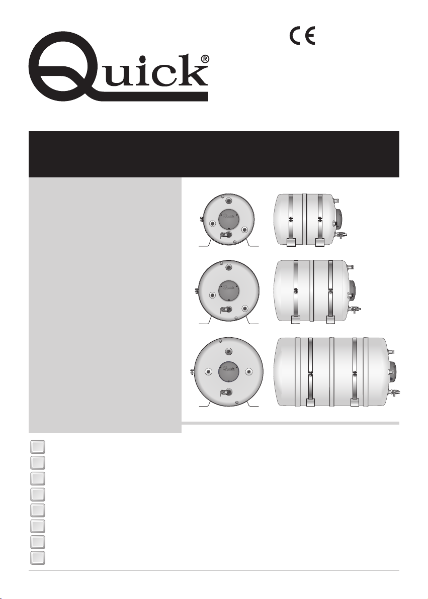
NAUTIC WATER HEATER
Our long experience operating in the nautical field has given us the means to supply a new series of water heat-
ers with innovative characteristics compared with other heaters available on the market.
The advantages given by Quick®Nautic boilers, are:
• high quality of materials ensure the product is both reliable and long lasting.
• Heat exchanger with a large exchanging surface.
• Producing hot water also by means of an electric element, which is provided with an adjustable and safety
thermostat.
• Relief/non return valve that protects the tank against overpressure and drains off water from the boiler when
no longer used.
• The installation is easy and practical on a flat area.
BEFORE USING THE WATER HEATER READ CAREFULLY THIS INSTRUCTION MANUAL.
IF IN DOUBT, PLEASE CONTACT THE NEAREST “QUICK®” DEALER.
WARNING: use this water heater in the applications described in this manual. Don’t use the equipment
for any other purpose. Quick®will not be held responsible for damage to equipment and/or personal inju-
ries caused by a misusage of the equipment.
PACKAGE CONTAINS: water heater - mounting - bolts, nuts and screws (for assembly) - user’s manual - condi-
tions of warranty.
INSTALLATION SITE
The water heater has to be placed in a dry and well-ventilated location. This precaution is required, even though
water heaters are made of sea environment resistant materials, since electrical systems are present (in models
provided). Moreover, if installed in non-ventilated environments, condensation could occur and could be mistak-
en for a leak.
INSTALLATION
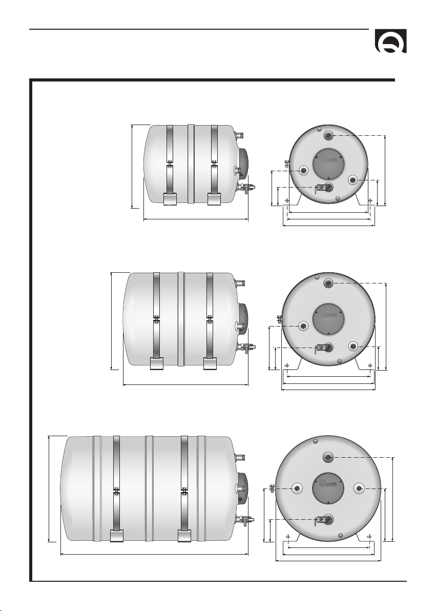
• Put mounting (17) on the tank (1) using studs and nuts provided (18, 19, 20).
• Fix water heater on flat surface or inclined plane or wall, as shown in fig. 1, using proper mountings for the
weight of the water heater and for the type of installation site in the boat.
WARNING: the weight of water heater/unit in the technical data refers to the empty unit. In order to
have the gross weight add to the empty weight, the water amount. (1 liter of water will almost weigh 1
Kg. / 2,2 lb).
• Carry out the hydraulic connections, relating to the input and output of tap water and from the engine
cooling to the heat exchanger, as shown in fig. 2. Keep the connections between engine cooling system and
heat exchanger as short as possible.
WARNING: the overpressure release pipe must be positioned sloping evenly downwards in a location
protected from the formation of ice.
WARNING: water might drip from the overpressure release pipe of the device, and this pipe must be left
open to the atmosphere.
WARNING: when fittings are used on water outlets, use Loctite 243, 577 or Teflon on the threads in order
to ensure tightness. Make sure that there is no water leakage.


 Operation and maintenance instructions")