Thermo King SB-400 User manual

SB-400
TK 51113-2-MM (Rev. 2, 08/02)
Copyright©2001 Thermo King Corp., Minneapolis, MN, U.S.A. Printed in
U.S.A.

2
This manual is published for informational purposes only and the information so provided should
not be considered as all-inclusive or covering all contingencies. If further information is required,
Thermo King Corporation should be consulted.
Sale of product shown in this manual is subject to Thermo King’s terms and conditions
including, but not limited to, the Thermo King Limited Express Warranty. Such terms and
conditions are available upon request. Thermo King’s warranty will not apply to any
equipment which has been “so repaired or altered outside the manufacturer’s plants as,
in the manufacturer’s judgment, to effect its stability.”
No warranties, express or implied, including warranties of fitness for a particular
purpose or merchantability, or warranties arising from course of dealing or usage of
trade, are made regarding the information, recommendations, and descriptions
contained herein. Manufacturer is not responsible and will not be held liable in contract
or in tort (including negligence) for any special, indirect or consequential damages,
including injury or damage caused to vehicles, contents or persons, by reason of the
installation of any Thermo King product or its mechanical failure.
The maintenance information in this manual covers unit models:
System SB-400 30 (918593)
SB-400 (002004)
For further information, refer to:
THERMOGUARD µP-VI Microprocessor for Screw Compressor Applications
Diagnostic Manual TK 51329
SB-400 Refrigeration System Manual TK 51696
SB-400 Operator’s Manual TK 51212
SB-400 Parts Manual TK 51356
DAS Data Acquisition System Manual TK 50565
TK 482 and TK 486 Engine Overhaul Manual TK 50136
S391 Screw Compressor Overhaul Manual TK 50567
Tool Catalog TK 5955
Evacuation Station Operation and Field Application TK 40612
ElectroStatic Discharge (ESD) Training Guide TK 40282
The information in this manual is provided to assist owners, operators and service people in the proper upkeep
and maintenance of Thermo King units.

3
Recover Refrigerant
At Thermo King, we recognize the need to preserve the environment
and limit the potential harm to the ozone layer that can result from
allowing refrigerant to escape into the atmosphere.
We strictly adhere to a policy that promotes the recovery and limits
the loss of refrigerant into the atmosphere.
In addition, service personnel must be aware of Federal regulations
concerning the use of refrigerants and the certification of
technicians. For additional information on regulations and technician
certification programs, contact your local Thermo King dealer.

4

5
Table of Contents
List of Figures . . . . . . . . . . . . . . . . . . . . . . . . . . . . . . . . . . . . . . . . . . . . . . . . . . . . . . . . . . . . . . . . . . . . . . . . . . . 9
Safety Precautions . . . . . . . . . . . . . . . . . . . . . . . . . . . . . . . . . . . . . . . . . . . . . . . . . . . . . . . . . . . . . . . . . . . . . . 11
General Practices . . . . . . . . . . . . . . . . . . . . . . . . . . . . . . . . . . . . . . . . . . . . . . . . . . . . . . . . . . . . . . . . . . . . . . . . 11
Refrigerant . . . . . . . . . . . . . . . . . . . . . . . . . . . . . . . . . . . . . . . . . . . . . . . . . . . . . . . . . . . . . . . . . . . . . . . . . . . . . 11
Refrigerant Oil . . . . . . . . . . . . . . . . . . . . . . . . . . . . . . . . . . . . . . . . . . . . . . . . . . . . . . . . . . . . . . . . . . . . . . . . . . . 11
Specifications . . . . . . . . . . . . . . . . . . . . . . . . . . . . . . . . . . . . . . . . . . . . . . . . . . . . . . . . . . . . . . . . . . . . . . . . . . 13
Engine . . . . . . . . . . . . . . . . . . . . . . . . . . . . . . . . . . . . . . . . . . . . . . . . . . . . . . . . . . . . . . . . . . . . . . . . . . . . . . . . . 13
Belt Tension . . . . . . . . . . . . . . . . . . . . . . . . . . . . . . . . . . . . . . . . . . . . . . . . . . . . . . . . . . . . . . . . . . . . . . . . . . . . 14
Refrigeration System . . . . . . . . . . . . . . . . . . . . . . . . . . . . . . . . . . . . . . . . . . . . . . . . . . . . . . . . . . . . . . . . . . . . . 14
Electrical Control System . . . . . . . . . . . . . . . . . . . . . . . . . . . . . . . . . . . . . . . . . . . . . . . . . . . . . . . . . . . . . . . . . . 14
Electrical Components . . . . . . . . . . . . . . . . . . . . . . . . . . . . . . . . . . . . . . . . . . . . . . . . . . . . . . . . . . . . . . . . . . . . 15
SMART REEFER µP-VI Microprocessor Temperature Controller . . . . . . . . . . . . . . . . . . . . . . . . . . . . . . . . . . . 15
Design Features and Unit Photos . . . . . . . . . . . . . . . . . . . . . . . . . . . . . . . . . . . . . . . . . . . . . . . . . . . . . . . . . . 17
Design Features . . . . . . . . . . . . . . . . . . . . . . . . . . . . . . . . . . . . . . . . . . . . . . . . . . . . . . . . . . . . . . . . . . . . . . . . . 17
Serial Number Locations . . . . . . . . . . . . . . . . . . . . . . . . . . . . . . . . . . . . . . . . . . . . . . . . . . . . . . . . . . . . . . . . . . . 18
Unit Photos . . . . . . . . . . . . . . . . . . . . . . . . . . . . . . . . . . . . . . . . . . . . . . . . . . . . . . . . . . . . . . . . . . . . . . . . . . . . . 19
Maintenance Inspection Schedule . . . . . . . . . . . . . . . . . . . . . . . . . . . . . . . . . . . . . . . . . . . . . . . . . . . . . . . . . 25
Unit Description . . . . . . . . . . . . . . . . . . . . . . . . . . . . . . . . . . . . . . . . . . . . . . . . . . . . . . . . . . . . . . . . . . . . . . . . 27
General Description . . . . . . . . . . . . . . . . . . . . . . . . . . . . . . . . . . . . . . . . . . . . . . . . . . . . . . . . . . . . . . . . . . . . . . 27
SMART REEFER µP-VI Microprocessor . . . . . . . . . . . . . . . . . . . . . . . . . . . . . . . . . . . . . . . . . . . . . . . . . . . 27
CYCLE-SENTRY Start-Stop Controls . . . . . . . . . . . . . . . . . . . . . . . . . . . . . . . . . . . . . . . . . . . . . . . . . . . . . 27
Data Logging . . . . . . . . . . . . . . . . . . . . . . . . . . . . . . . . . . . . . . . . . . . . . . . . . . . . . . . . . . . . . . . . . . . . . . . . 28
DAS . . . . . . . . . . . . . . . . . . . . . . . . . . . . . . . . . . . . . . . . . . . . . . . . . . . . . . . . . . . . . . . . . . . . . . . . . . . . . . . 28
Tracker . . . . . . . . . . . . . . . . . . . . . . . . . . . . . . . . . . . . . . . . . . . . . . . . . . . . . . . . . . . . . . . . . . . . . . . . . . . . . 28
Electronic Throttling Valve (ETV) . . . . . . . . . . . . . . . . . . . . . . . . . . . . . . . . . . . . . . . . . . . . . . . . . . . . . . . . . 28
Refrigeration System Components . . . . . . . . . . . . . . . . . . . . . . . . . . . . . . . . . . . . . . . . . . . . . . . . . . . . . . . . 28
Thermo King S391 Screw Compressor with Loading Valves . . . . . . . . . . . . . . . . . . . . . . . . . . . . . . . . . . . . 30
Refrigeration System . . . . . . . . . . . . . . . . . . . . . . . . . . . . . . . . . . . . . . . . . . . . . . . . . . . . . . . . . . . . . . . . . . 30
Sequence of Operation . . . . . . . . . . . . . . . . . . . . . . . . . . . . . . . . . . . . . . . . . . . . . . . . . . . . . . . . . . . . . . . . . . . . 31
Operating Modes . . . . . . . . . . . . . . . . . . . . . . . . . . . . . . . . . . . . . . . . . . . . . . . . . . . . . . . . . . . . . . . . . . . . . 31
Special Start-up Modes . . . . . . . . . . . . . . . . . . . . . . . . . . . . . . . . . . . . . . . . . . . . . . . . . . . . . . . . . . . . . . . . 41
Compressor Temperature (CTMP) System . . . . . . . . . . . . . . . . . . . . . . . . . . . . . . . . . . . . . . . . . . . . . . . . . . . . 42
Auxiliary Modes . . . . . . . . . . . . . . . . . . . . . . . . . . . . . . . . . . . . . . . . . . . . . . . . . . . . . . . . . . . . . . . . . . . . . . . . . . 42
Alarm Codes . . . . . . . . . . . . . . . . . . . . . . . . . . . . . . . . . . . . . . . . . . . . . . . . . . . . . . . . . . . . . . . . . . . . . . . . . . . . 43
Operating Instructions . . . . . . . . . . . . . . . . . . . . . . . . . . . . . . . . . . . . . . . . . . . . . . . . . . . . . . . . . . . . . . . . . . . 45
Control Panel . . . . . . . . . . . . . . . . . . . . . . . . . . . . . . . . . . . . . . . . . . . . . . . . . . . . . . . . . . . . . . . . . . . . . . . . . . . 45
On/Off Switch . . . . . . . . . . . . . . . . . . . . . . . . . . . . . . . . . . . . . . . . . . . . . . . . . . . . . . . . . . . . . . . . . . . . . . . . 45
Optional On/Off/Sleep Switch . . . . . . . . . . . . . . . . . . . . . . . . . . . . . . . . . . . . . . . . . . . . . . . . . . . . . . . . . . . . 46
Display . . . . . . . . . . . . . . . . . . . . . . . . . . . . . . . . . . . . . . . . . . . . . . . . . . . . . . . . . . . . . . . . . . . . . . . . . . . . . 46
Keypad . . . . . . . . . . . . . . . . . . . . . . . . . . . . . . . . . . . . . . . . . . . . . . . . . . . . . . . . . . . . . . . . . . . . . . . . . . . . . 46
Computer Port . . . . . . . . . . . . . . . . . . . . . . . . . . . . . . . . . . . . . . . . . . . . . . . . . . . . . . . . . . . . . . . . . . . . . . . 47
Printer Port . . . . . . . . . . . . . . . . . . . . . . . . . . . . . . . . . . . . . . . . . . . . . . . . . . . . . . . . . . . . . . . . . . . . . . . . . . 47
Unit Indicators . . . . . . . . . . . . . . . . . . . . . . . . . . . . . . . . . . . . . . . . . . . . . . . . . . . . . . . . . . . . . . . . . . . . . . . . . . . 47
Unit Protection Devices . . . . . . . . . . . . . . . . . . . . . . . . . . . . . . . . . . . . . . . . . . . . . . . . . . . . . . . . . . . . . . . . . . . . 47
Unit Operation . . . . . . . . . . . . . . . . . . . . . . . . . . . . . . . . . . . . . . . . . . . . . . . . . . . . . . . . . . . . . . . . . . . . . . . . . . . 48
Manual Pretrip Inspection (Before Starting Unit) . . . . . . . . . . . . . . . . . . . . . . . . . . . . . . . . . . . . . . . . . . . . . 48
Starting Unit With Electronic Full Pretrip . . . . . . . . . . . . . . . . . . . . . . . . . . . . . . . . . . . . . . . . . . . . . . . . . . . 49
Selection of Operating Modes . . . . . . . . . . . . . . . . . . . . . . . . . . . . . . . . . . . . . . . . . . . . . . . . . . . . . . . . . . . 50
Restarting Unit . . . . . . . . . . . . . . . . . . . . . . . . . . . . . . . . . . . . . . . . . . . . . . . . . . . . . . . . . . . . . . . . . . . . . . . 50
After Start Inspection . . . . . . . . . . . . . . . . . . . . . . . . . . . . . . . . . . . . . . . . . . . . . . . . . . . . . . . . . . . . . . . . . . 51
Loading Procedure . . . . . . . . . . . . . . . . . . . . . . . . . . . . . . . . . . . . . . . . . . . . . . . . . . . . . . . . . . . . . . . . . . . . 51
Post Load Procedure . . . . . . . . . . . . . . . . . . . . . . . . . . . . . . . . . . . . . . . . . . . . . . . . . . . . . . . . . . . . . . . . . . 51
Post Trip Checks . . . . . . . . . . . . . . . . . . . . . . . . . . . . . . . . . . . . . . . . . . . . . . . . . . . . . . . . . . . . . . . . . . . . . 51

Table of Contents
6
Electrical Maintenance . . . . . . . . . . . . . . . . . . . . . . . . . . . . . . . . . . . . . . . . . . . . . . . . . . . . . . . . . . . . . . . . . . .53
Alternator (Australian Bosch) . . . . . . . . . . . . . . . . . . . . . . . . . . . . . . . . . . . . . . . . . . . . . . . . . . . . . . . . . . . . . . . .53
Charging System Diagnostic Procedures . . . . . . . . . . . . . . . . . . . . . . . . . . . . . . . . . . . . . . . . . . . . . . . . . . .53
Battery . . . . . . . . . . . . . . . . . . . . . . . . . . . . . . . . . . . . . . . . . . . . . . . . . . . . . . . . . . . . . . . . . . . . . . . . . . . . . . . . .56
Unit Wiring . . . . . . . . . . . . . . . . . . . . . . . . . . . . . . . . . . . . . . . . . . . . . . . . . . . . . . . . . . . . . . . . . . . . . . . . . . . . . .56
Fuses . . . . . . . . . . . . . . . . . . . . . . . . . . . . . . . . . . . . . . . . . . . . . . . . . . . . . . . . . . . . . . . . . . . . . . . . . . . . . . . . . .56
Fuse Link . . . . . . . . . . . . . . . . . . . . . . . . . . . . . . . . . . . . . . . . . . . . . . . . . . . . . . . . . . . . . . . . . . . . . . . . . . . . . . .57
Air Heater . . . . . . . . . . . . . . . . . . . . . . . . . . . . . . . . . . . . . . . . . . . . . . . . . . . . . . . . . . . . . . . . . . . . . . . . . . . . . .57
SMART REEFER µP-VI Microprocessor Controller . . . . . . . . . . . . . . . . . . . . . . . . . . . . . . . . . . . . . . . . . . . . . .57
Engine Maintenance . . . . . . . . . . . . . . . . . . . . . . . . . . . . . . . . . . . . . . . . . . . . . . . . . . . . . . . . . . . . . . . . . . . . .59
EMI 3000 . . . . . . . . . . . . . . . . . . . . . . . . . . . . . . . . . . . . . . . . . . . . . . . . . . . . . . . . . . . . . . . . . . . . . . . . . . . . . . .59
Engine Lubrication System . . . . . . . . . . . . . . . . . . . . . . . . . . . . . . . . . . . . . . . . . . . . . . . . . . . . . . . . . . . . . . . . .59
Engine Oil Change . . . . . . . . . . . . . . . . . . . . . . . . . . . . . . . . . . . . . . . . . . . . . . . . . . . . . . . . . . . . . . . . . . . .59
Oil Filter Change . . . . . . . . . . . . . . . . . . . . . . . . . . . . . . . . . . . . . . . . . . . . . . . . . . . . . . . . . . . . . . . . . . . . . .59
Low Oil Pressure . . . . . . . . . . . . . . . . . . . . . . . . . . . . . . . . . . . . . . . . . . . . . . . . . . . . . . . . . . . . . . . . . . . . . .59
Engine Cooling System . . . . . . . . . . . . . . . . . . . . . . . . . . . . . . . . . . . . . . . . . . . . . . . . . . . . . . . . . . . . . . . . . . . .61
ELC (Extended Life Coolant) . . . . . . . . . . . . . . . . . . . . . . . . . . . . . . . . . . . . . . . . . . . . . . . . . . . . . . . . . . . .61
Antifreeze Maintenance Procedure . . . . . . . . . . . . . . . . . . . . . . . . . . . . . . . . . . . . . . . . . . . . . . . . . . . . . . . .62
Bleeding Air From The Cooling System . . . . . . . . . . . . . . . . . . . . . . . . . . . . . . . . . . . . . . . . . . . . . . . . . . . .63
Engine Thermostat . . . . . . . . . . . . . . . . . . . . . . . . . . . . . . . . . . . . . . . . . . . . . . . . . . . . . . . . . . . . . . . . . . . .64
Engine Fuel System . . . . . . . . . . . . . . . . . . . . . . . . . . . . . . . . . . . . . . . . . . . . . . . . . . . . . . . . . . . . . . . . . . . . . .64
Operation . . . . . . . . . . . . . . . . . . . . . . . . . . . . . . . . . . . . . . . . . . . . . . . . . . . . . . . . . . . . . . . . . . . . . . . . . . .64
Maintenance . . . . . . . . . . . . . . . . . . . . . . . . . . . . . . . . . . . . . . . . . . . . . . . . . . . . . . . . . . . . . . . . . . . . . . . . .64
Bleeding The Fuel System . . . . . . . . . . . . . . . . . . . . . . . . . . . . . . . . . . . . . . . . . . . . . . . . . . . . . . . . . . . . . .66
Draining Water from Fuel Tank . . . . . . . . . . . . . . . . . . . . . . . . . . . . . . . . . . . . . . . . . . . . . . . . . . . . . . . . . . .66
Fuel Filter/Water Separator . . . . . . . . . . . . . . . . . . . . . . . . . . . . . . . . . . . . . . . . . . . . . . . . . . . . . . . . . . . . . .66
Fuel Filter/Water Separator Replacement . . . . . . . . . . . . . . . . . . . . . . . . . . . . . . . . . . . . . . . . . . . . . . . . . .66
Engine Speed Adjustments . . . . . . . . . . . . . . . . . . . . . . . . . . . . . . . . . . . . . . . . . . . . . . . . . . . . . . . . . . . . . .67
Injection Pump Timing . . . . . . . . . . . . . . . . . . . . . . . . . . . . . . . . . . . . . . . . . . . . . . . . . . . . . . . . . . . . . . . . .68
Injection Pump Removal . . . . . . . . . . . . . . . . . . . . . . . . . . . . . . . . . . . . . . . . . . . . . . . . . . . . . . . . . . . . . . . .69
Injection Pump Reinstallation . . . . . . . . . . . . . . . . . . . . . . . . . . . . . . . . . . . . . . . . . . . . . . . . . . . . . . . . . . . .70
Fuel Solenoid . . . . . . . . . . . . . . . . . . . . . . . . . . . . . . . . . . . . . . . . . . . . . . . . . . . . . . . . . . . . . . . . . . . . . . . .71
Engine Valve Clearance Adjustment . . . . . . . . . . . . . . . . . . . . . . . . . . . . . . . . . . . . . . . . . . . . . . . . . . . . . . . . . .73
Crankcase Breather . . . . . . . . . . . . . . . . . . . . . . . . . . . . . . . . . . . . . . . . . . . . . . . . . . . . . . . . . . . . . . . . . . . . . . .74
EMI 3000 Air Cleaner . . . . . . . . . . . . . . . . . . . . . . . . . . . . . . . . . . . . . . . . . . . . . . . . . . . . . . . . . . . . . . . . . . . . .75
Air Restriction Indicator . . . . . . . . . . . . . . . . . . . . . . . . . . . . . . . . . . . . . . . . . . . . . . . . . . . . . . . . . . . . . . . . . . . .75
Belts . . . . . . . . . . . . . . . . . . . . . . . . . . . . . . . . . . . . . . . . . . . . . . . . . . . . . . . . . . . . . . . . . . . . . . . . . . . . . . . . . . .75
Alternator Belt Adjustment . . . . . . . . . . . . . . . . . . . . . . . . . . . . . . . . . . . . . . . . . . . . . . . . . . . . . . . . . . . . . .76
Upper And Lower Fan Belt Adjustment . . . . . . . . . . . . . . . . . . . . . . . . . . . . . . . . . . . . . . . . . . . . . . . . . . . . .76
Fan Belt Removal and Installation . . . . . . . . . . . . . . . . . . . . . . . . . . . . . . . . . . . . . . . . . . . . . . . . . . . . . . . .77
Refrigeration Maintenance . . . . . . . . . . . . . . . . . . . . . . . . . . . . . . . . . . . . . . . . . . . . . . . . . . . . . . . . . . . . . . . .79
Suction Pressures . . . . . . . . . . . . . . . . . . . . . . . . . . . . . . . . . . . . . . . . . . . . . . . . . . . . . . . . . . . . . . . . . . . . . . . .79
Refrigerant Charge . . . . . . . . . . . . . . . . . . . . . . . . . . . . . . . . . . . . . . . . . . . . . . . . . . . . . . . . . . . . . . . . . . . . . . .80
Testing The Refrigerant Charge With An Empty Trailer . . . . . . . . . . . . . . . . . . . . . . . . . . . . . . . . . . . . . . . .80
Testing The Refrigerant Charge With A Loaded Trailer . . . . . . . . . . . . . . . . . . . . . . . . . . . . . . . . . . . . . . . .80
Testing for an Overcharge . . . . . . . . . . . . . . . . . . . . . . . . . . . . . . . . . . . . . . . . . . . . . . . . . . . . . . . . . . . . . .80
Moisture Indicating Sight Glass . . . . . . . . . . . . . . . . . . . . . . . . . . . . . . . . . . . . . . . . . . . . . . . . . . . . . . . . . .81
Refrigerant Leaks . . . . . . . . . . . . . . . . . . . . . . . . . . . . . . . . . . . . . . . . . . . . . . . . . . . . . . . . . . . . . . . . . . . . . . . .81
Compressor Shaft Seal Leak Check . . . . . . . . . . . . . . . . . . . . . . . . . . . . . . . . . . . . . . . . . . . . . . . . . . . . . . .82
Checking Compressor Oil . . . . . . . . . . . . . . . . . . . . . . . . . . . . . . . . . . . . . . . . . . . . . . . . . . . . . . . . . . . . . . . . . .82
Adding Compressor Oil . . . . . . . . . . . . . . . . . . . . . . . . . . . . . . . . . . . . . . . . . . . . . . . . . . . . . . . . . . . . . . . . . . . .83
Compressor Pump Down . . . . . . . . . . . . . . . . . . . . . . . . . . . . . . . . . . . . . . . . . . . . . . . . . . . . . . . . . . . . . . . . . .84
Low Side Pump Down . . . . . . . . . . . . . . . . . . . . . . . . . . . . . . . . . . . . . . . . . . . . . . . . . . . . . . . . . . . . . . . . . . . . .84
High Pressure Cut In Switch (HPCI) Test . . . . . . . . . . . . . . . . . . . . . . . . . . . . . . . . . . . . . . . . . . . . . . . . . . . . . .85
High Pressure Cutout Switch (HPCO) Test . . . . . . . . . . . . . . . . . . . . . . . . . . . . . . . . . . . . . . . . . . . . . . . . . . . . .85
Three-Way Valve Condenser Pressure Bypass Check Valve . . . . . . . . . . . . . . . . . . . . . . . . . . . . . . . . . . . . . . .86
Electronic Throttling Valve (ETV) . . . . . . . . . . . . . . . . . . . . . . . . . . . . . . . . . . . . . . . . . . . . . . . . . . . . . . . . . . . .87
Pressure Transducers . . . . . . . . . . . . . . . . . . . . . . . . . . . . . . . . . . . . . . . . . . . . . . . . . . . . . . . . . . . . . . . . . . . . .88
Loading Valve Test . . . . . . . . . . . . . . . . . . . . . . . . . . . . . . . . . . . . . . . . . . . . . . . . . . . . . . . . . . . . . . . . . . . . . . .88

Table of Contents
7
Refrigeration Maintenance (continued)
Liquid Line Solenoid Test . . . . . . . . . . . . . . . . . . . . . . . . . . . . . . . . . . . . . . . . . . . . . . . . . . . . . . . . . . . . . . . . . . 89
Liquid Injection Valve Test . . . . . . . . . . . . . . . . . . . . . . . . . . . . . . . . . . . . . . . . . . . . . . . . . . . . . . . . . . . . . . . . . 90
Water Valve Test . . . . . . . . . . . . . . . . . . . . . . . . . . . . . . . . . . . . . . . . . . . . . . . . . . . . . . . . . . . . . . . . . . . . . . . . 90
Heat Check Valve Test . . . . . . . . . . . . . . . . . . . . . . . . . . . . . . . . . . . . . . . . . . . . . . . . . . . . . . . . . . . . . . . . . . . . 91
Compressor Test . . . . . . . . . . . . . . . . . . . . . . . . . . . . . . . . . . . . . . . . . . . . . . . . . . . . . . . . . . . . . . . . . . . . . . . . 92
Refrigeration Service Operations . . . . . . . . . . . . . . . . . . . . . . . . . . . . . . . . . . . . . . . . . . . . . . . . . . . . . . . . . . 97
Compressor . . . . . . . . . . . . . . . . . . . . . . . . . . . . . . . . . . . . . . . . . . . . . . . . . . . . . . . . . . . . . . . . . . . . . . . . . . . . 97
Compressor Coupling Removal . . . . . . . . . . . . . . . . . . . . . . . . . . . . . . . . . . . . . . . . . . . . . . . . . . . . . . . . . . 97
Compressor Coupling Installation . . . . . . . . . . . . . . . . . . . . . . . . . . . . . . . . . . . . . . . . . . . . . . . . . . . . . . . . . 98
Compressor Repair . . . . . . . . . . . . . . . . . . . . . . . . . . . . . . . . . . . . . . . . . . . . . . . . . . . . . . . . . . . . . . . . . . . 99
System Clean-up Procedures . . . . . . . . . . . . . . . . . . . . . . . . . . . . . . . . . . . . . . . . . . . . . . . . . . . . . . . . . . . . . . 100
System Clean-Up Procedure Using Internal Oil Filter Replacement . . . . . . . . . . . . . . . . . . . . . . . . . . . . . 100
System Clean-Up Procedure Using Screw Compressor Clean-Up Kit P/N 204-920 . . . . . . . . . . . . . . . . . 100
In-line Condenser Check Valve . . . . . . . . . . . . . . . . . . . . . . . . . . . . . . . . . . . . . . . . . . . . . . . . . . . . . . . . . . . . 102
Condenser Check Valve Replacement . . . . . . . . . . . . . . . . . . . . . . . . . . . . . . . . . . . . . . . . . . . . . . . . . . . . . . . 102
Discharge Vibrasorber . . . . . . . . . . . . . . . . . . . . . . . . . . . . . . . . . . . . . . . . . . . . . . . . . . . . . . . . . . . . . . . . . . . 102
Receiver Tank . . . . . . . . . . . . . . . . . . . . . . . . . . . . . . . . . . . . . . . . . . . . . . . . . . . . . . . . . . . . . . . . . . . . . . . . . . 102
Filter Drier . . . . . . . . . . . . . . . . . . . . . . . . . . . . . . . . . . . . . . . . . . . . . . . . . . . . . . . . . . . . . . . . . . . . . . . . . . . . . 103
Evaporator Expansion Valve . . . . . . . . . . . . . . . . . . . . . . . . . . . . . . . . . . . . . . . . . . . . . . . . . . . . . . . . . . . . . . . 103
Checking Evaporator Expansion Valve Superheat . . . . . . . . . . . . . . . . . . . . . . . . . . . . . . . . . . . . . . . . . . . . . . 104
Evaporator Coil . . . . . . . . . . . . . . . . . . . . . . . . . . . . . . . . . . . . . . . . . . . . . . . . . . . . . . . . . . . . . . . . . . . . . . . . . 104
Three-way Valve Repair . . . . . . . . . . . . . . . . . . . . . . . . . . . . . . . . . . . . . . . . . . . . . . . . . . . . . . . . . . . . . . . . . . 105
Removal/Disassembly . . . . . . . . . . . . . . . . . . . . . . . . . . . . . . . . . . . . . . . . . . . . . . . . . . . . . . . . . . . . . . . . 105
End Cap Checks . . . . . . . . . . . . . . . . . . . . . . . . . . . . . . . . . . . . . . . . . . . . . . . . . . . . . . . . . . . . . . . . . . . . . 106
Assembly/Installation . . . . . . . . . . . . . . . . . . . . . . . . . . . . . . . . . . . . . . . . . . . . . . . . . . . . . . . . . . . . . . . . . 107
Three-Way Valve Condenser Pressure Bypass Check Valve Repair . . . . . . . . . . . . . . . . . . . . . . . . . . . . . . . . 108
Pilot Solenoid . . . . . . . . . . . . . . . . . . . . . . . . . . . . . . . . . . . . . . . . . . . . . . . . . . . . . . . . . . . . . . . . . . . . . . . . . . 109
Suction Vibrasorbers . . . . . . . . . . . . . . . . . . . . . . . . . . . . . . . . . . . . . . . . . . . . . . . . . . . . . . . . . . . . . . . . . . . . . 109
High Pressure Cutout And High Pressure Cut In Switches . . . . . . . . . . . . . . . . . . . . . . . . . . . . . . . . . . . . . . . . 109
High Pressure Relief Valve . . . . . . . . . . . . . . . . . . . . . . . . . . . . . . . . . . . . . . . . . . . . . . . . . . . . . . . . . . . . . . . . 110
Liquid Line Solenoid . . . . . . . . . . . . . . . . . . . . . . . . . . . . . . . . . . . . . . . . . . . . . . . . . . . . . . . . . . . . . . . . . . . . . 110
Subcooler/Condenser/Radiator . . . . . . . . . . . . . . . . . . . . . . . . . . . . . . . . . . . . . . . . . . . . . . . . . . . . . . . . . . . . . 110
Discharge Pressure Transducer . . . . . . . . . . . . . . . . . . . . . . . . . . . . . . . . . . . . . . . . . . . . . . . . . . . . . . . . . . . . 111
Suction Pressure Transducer . . . . . . . . . . . . . . . . . . . . . . . . . . . . . . . . . . . . . . . . . . . . . . . . . . . . . . . . . . . . . . 111
Electronic Throttling Valve (ETV) . . . . . . . . . . . . . . . . . . . . . . . . . . . . . . . . . . . . . . . . . . . . . . . . . . . . . . . . . . . 111
Economizer Heat Exchanger . . . . . . . . . . . . . . . . . . . . . . . . . . . . . . . . . . . . . . . . . . . . . . . . . . . . . . . . . . . . . . 113
Economizer Expansion Valve . . . . . . . . . . . . . . . . . . . . . . . . . . . . . . . . . . . . . . . . . . . . . . . . . . . . . . . . . . . . . . 113
Checking Economizer Expansion Valve Superheat . . . . . . . . . . . . . . . . . . . . . . . . . . . . . . . . . . . . . . . . . . . . . 114
Heat Check Valve Repair . . . . . . . . . . . . . . . . . . . . . . . . . . . . . . . . . . . . . . . . . . . . . . . . . . . . . . . . . . . . . . . . . 115
Heat Check Valve Replacement . . . . . . . . . . . . . . . . . . . . . . . . . . . . . . . . . . . . . . . . . . . . . . . . . . . . . . . . . . . . 115
Liquid Injection Valve . . . . . . . . . . . . . . . . . . . . . . . . . . . . . . . . . . . . . . . . . . . . . . . . . . . . . . . . . . . . . . . . . . . . 116
Structural Maintenance . . . . . . . . . . . . . . . . . . . . . . . . . . . . . . . . . . . . . . . . . . . . . . . . . . . . . . . . . . . . . . . . . 117
Unit and Engine Mounting Bolts . . . . . . . . . . . . . . . . . . . . . . . . . . . . . . . . . . . . . . . . . . . . . . . . . . . . . . . . . . . . 117
Unit Inspection . . . . . . . . . . . . . . . . . . . . . . . . . . . . . . . . . . . . . . . . . . . . . . . . . . . . . . . . . . . . . . . . . . . . . . . . . 117
Condenser, Evaporator, And Radiator Coils . . . . . . . . . . . . . . . . . . . . . . . . . . . . . . . . . . . . . . . . . . . . . . . . . . . 117
Defrost Drains . . . . . . . . . . . . . . . . . . . . . . . . . . . . . . . . . . . . . . . . . . . . . . . . . . . . . . . . . . . . . . . . . . . . . . . . . . 117
Unit Installation . . . . . . . . . . . . . . . . . . . . . . . . . . . . . . . . . . . . . . . . . . . . . . . . . . . . . . . . . . . . . . . . . . . . . . . . . 117
Defrost Damper . . . . . . . . . . . . . . . . . . . . . . . . . . . . . . . . . . . . . . . . . . . . . . . . . . . . . . . . . . . . . . . . . . . . . . . . . 118
Condenser and Evaporator Fan Location . . . . . . . . . . . . . . . . . . . . . . . . . . . . . . . . . . . . . . . . . . . . . . . . . . . . . 119
Condenser Fan Blower . . . . . . . . . . . . . . . . . . . . . . . . . . . . . . . . . . . . . . . . . . . . . . . . . . . . . . . . . . . . . . . . 119
Evaporator Fan Blower . . . . . . . . . . . . . . . . . . . . . . . . . . . . . . . . . . . . . . . . . . . . . . . . . . . . . . . . . . . . . . . . 119
Fan Shaft Assembly . . . . . . . . . . . . . . . . . . . . . . . . . . . . . . . . . . . . . . . . . . . . . . . . . . . . . . . . . . . . . . . . . . . . . 120
Fan Shaft Assembly Overhaul . . . . . . . . . . . . . . . . . . . . . . . . . . . . . . . . . . . . . . . . . . . . . . . . . . . . . . . . . . 120
Idler Assembly . . . . . . . . . . . . . . . . . . . . . . . . . . . . . . . . . . . . . . . . . . . . . . . . . . . . . . . . . . . . . . . . . . . . . . . . . 121
Idler Assembly Overhaul . . . . . . . . . . . . . . . . . . . . . . . . . . . . . . . . . . . . . . . . . . . . . . . . . . . . . . . . . . . . . . 121
Mechanical Diagnosis . . . . . . . . . . . . . . . . . . . . . . . . . . . . . . . . . . . . . . . . . . . . . . . . . . . . . . . . . . . . . . . . . . 123

Table of Contents
8
Refrigeration Diagnosis . . . . . . . . . . . . . . . . . . . . . . . . . . . . . . . . . . . . . . . . . . . . . . . . . . . . . . . . . . . . . . . . .127
Refrigeration System Diagnosis . . . . . . . . . . . . . . . . . . . . . . . . . . . . . . . . . . . . . . . . . . . . . . . . . . . . . . . . . . . .127
Diagnosis Procedure . . . . . . . . . . . . . . . . . . . . . . . . . . . . . . . . . . . . . . . . . . . . . . . . . . . . . . . . . . . . . . . . . .127
Refrigeration Diagnosis Charts . . . . . . . . . . . . . . . . . . . . . . . . . . . . . . . . . . . . . . . . . . . . . . . . . . . . . . . . . .129
Refrigeration Diagrams . . . . . . . . . . . . . . . . . . . . . . . . . . . . . . . . . . . . . . . . . . . . . . . . . . . . . . . . . . . . . . . . . .133
Index . . . . . . . . . . . . . . . . . . . . . . . . . . . . . . . . . . . . . . . . . . . . . . . . . . . . . . . . . . . . . . . . . . . . . . . . . . . . . . . . .137
Wiring Diagram Index . . . . . . . . . . . . . . . . . . . . . . . . . . . . . . . . . . . . . . . . . . . . . . . . . . . . . . . . . . . . . . . . . . .139

9
List of Figures
Figure 1: Compressor Serial Number Location . . . . . . . . . . . . . . . . . . . . . . . . . . . . . . . . . . . . . . . . . . . . . . . . . . 18
Figure 2: Unit Serial Number Locations . . . . . . . . . . . . . . . . . . . . . . . . . . . . . . . . . . . . . . . . . . . . . . . . . . . . . . . 18
Figure 3: Engine Serial Number Location . . . . . . . . . . . . . . . . . . . . . . . . . . . . . . . . . . . . . . . . . . . . . . . . . . . . . . 18
Figure 4: Front View . . . . . . . . . . . . . . . . . . . . . . . . . . . . . . . . . . . . . . . . . . . . . . . . . . . . . . . . . . . . . . . . . . . . . 19
Figure 5: Back View . . . . . . . . . . . . . . . . . . . . . . . . . . . . . . . . . . . . . . . . . . . . . . . . . . . . . . . . . . . . . . . . . . . . . 20
Figure 6: Front View with Doors Open . . . . . . . . . . . . . . . . . . . . . . . . . . . . . . . . . . . . . . . . . . . . . . . . . . . . . . . . 21
Figure 7: Engine Compartment . . . . . . . . . . . . . . . . . . . . . . . . . . . . . . . . . . . . . . . . . . . . . . . . . . . . . . . . . . . . . . 22
Figure 8: Control Panel . . . . . . . . . . . . . . . . . . . . . . . . . . . . . . . . . . . . . . . . . . . . . . . . . . . . . . . . . . . . . . . . . . . . 23
Figure 9: Refrigeration System Components . . . . . . . . . . . . . . . . . . . . . . . . . . . . . . . . . . . . . . . . . . . . . . . . . . 29
Figure 10: High and Low Speed Cool . . . . . . . . . . . . . . . . . . . . . . . . . . . . . . . . . . . . . . . . . . . . . . . . . . . . . . . . 33
Figure 11: Modulated Cool with LV1 Open . . . . . . . . . . . . . . . . . . . . . . . . . . . . . . . . . . . . . . . . . . . . . . . . . . . . 35
Figure 12: Running Null . . . . . . . . . . . . . . . . . . . . . . . . . . . . . . . . . . . . . . . . . . . . . . . . . . . . . . . . . . . . . . . . . . 37
Figure 13: Low Speed Heat . . . . . . . . . . . . . . . . . . . . . . . . . . . . . . . . . . . . . . . . . . . . . . . . . . . . . . . . . . . . . . . 39
Figure 14: Control Panel . . . . . . . . . . . . . . . . . . . . . . . . . . . . . . . . . . . . . . . . . . . . . . . . . . . . . . . . . . . . . . . . . . . 45
Figure 15: On/Off/Sleep Switch . . . . . . . . . . . . . . . . . . . . . . . . . . . . . . . . . . . . . . . . . . . . . . . . . . . . . . . . . . . . . 46
Figure 16: Check Points for Alternator Test . . . . . . . . . . . . . . . . . . . . . . . . . . . . . . . . . . . . . . . . . . . . . . . . . . . . 53
Figure 17: Full Field Test . . . . . . . . . . . . . . . . . . . . . . . . . . . . . . . . . . . . . . . . . . . . . . . . . . . . . . . . . . . . . . . . . 56
Figure 18: Relay Board . . . . . . . . . . . . . . . . . . . . . . . . . . . . . . . . . . . . . . . . . . . . . . . . . . . . . . . . . . . . . . . . . . . . 57
Figure 19: Air Heater . . . . . . . . . . . . . . . . . . . . . . . . . . . . . . . . . . . . . . . . . . . . . . . . . . . . . . . . . . . . . . . . . . . . . . 57
Figure 20: ELC Nameplate Located On Expansion Tank . . . . . . . . . . . . . . . . . . . . . . . . . . . . . . . . . . . . . . . . . . 61
Figure 21: Engine Cooling System . . . . . . . . . . . . . . . . . . . . . . . . . . . . . . . . . . . . . . . . . . . . . . . . . . . . . . . . . . . 63
Figure 22: Engine Fuel System . . . . . . . . . . . . . . . . . . . . . . . . . . . . . . . . . . . . . . . . . . . . . . . . . . . . . . . . . . . . . . 65
Figure 23: Fuel Tank . . . . . . . . . . . . . . . . . . . . . . . . . . . . . . . . . . . . . . . . . . . . . . . . . . . . . . . . . . . . . . . . . . . . . . 66
Figure 24: Injection Pump . . . . . . . . . . . . . . . . . . . . . . . . . . . . . . . . . . . . . . . . . . . . . . . . . . . . . . . . . . . . . . . . . . 66
Figure 25: Filling Fuel Filter/Water Separator . . . . . . . . . . . . . . . . . . . . . . . . . . . . . . . . . . . . . . . . . . . . . . . . . . . 67
Figure 26: Engine Speed Adjustments . . . . . . . . . . . . . . . . . . . . . . . . . . . . . . . . . . . . . . . . . . . . . . . . . . . . . . . . 67
Figure 27: Component Location . . . . . . . . . . . . . . . . . . . . . . . . . . . . . . . . . . . . . . . . . . . . . . . . . . . . . . . . . . . . . 68
Figure 28: Top Dead Center One and Four . . . . . . . . . . . . . . . . . . . . . . . . . . . . . . . . . . . . . . . . . . . . . . . . . . . . 68
Figure 29: Timing Mark Alignment . . . . . . . . . . . . . . . . . . . . . . . . . . . . . . . . . . . . . . . . . . . . . . . . . . . . . . . . . . . 69
Figure 30: Correct Injection Timing Mark Alignment . . . . . . . . . . . . . . . . . . . . . . . . . . . . . . . . . . . . . . . . . . . . . . 69
Figure 31: Fuel Solenoid Location . . . . . . . . . . . . . . . . . . . . . . . . . . . . . . . . . . . . . . . . . . . . . . . . . . . . . . . . . . . 71
Figure 32: Fuel Solenoid Connector Pin Identification . . . . . . . . . . . . . . . . . . . . . . . . . . . . . . . . . . . . . . . . . . . . 71
Figure 33: Fuel Solenoid Components . . . . . . . . . . . . . . . . . . . . . . . . . . . . . . . . . . . . . . . . . . . . . . . . . . . . . . . . 72
Figure 34: Top Dead Center One and Four . . . . . . . . . . . . . . . . . . . . . . . . . . . . . . . . . . . . . . . . . . . . . . . . . . . . 73
Figure 35: Adjusting the Valve Clearance . . . . . . . . . . . . . . . . . . . . . . . . . . . . . . . . . . . . . . . . . . . . . . . . . . . . . . 74
Figure 36: Crankcase Breather . . . . . . . . . . . . . . . . . . . . . . . . . . . . . . . . . . . . . . . . . . . . . . . . . . . . . . . . . . . . . . 74
Figure 37: EMI 3000 Air Cleaner Assembly . . . . . . . . . . . . . . . . . . . . . . . . . . . . . . . . . . . . . . . . . . . . . . . . . . . . 75
Figure 38: EMI 3000 Air Filter Element . . . . . . . . . . . . . . . . . . . . . . . . . . . . . . . . . . . . . . . . . . . . . . . . . . . . . . . . 75
Figure 39: Air Restriction Indicator . . . . . . . . . . . . . . . . . . . . . . . . . . . . . . . . . . . . . . . . . . . . . . . . . . . . . . . . . . . 75
Figure 40: Belt Arrangement . . . . . . . . . . . . . . . . . . . . . . . . . . . . . . . . . . . . . . . . . . . . . . . . . . . . . . . . . . . . . . . . 76
Figure 41: Condenser Blower Alignment . . . . . . . . . . . . . . . . . . . . . . . . . . . . . . . . . . . . . . . . . . . . . . . . . . . . . . 78
Figure 42: Gauge Installation . . . . . . . . . . . . . . . . . . . . . . . . . . . . . . . . . . . . . . . . . . . . . . . . . . . . . . . . . . . . . . . 79
Figure 43: Moisture Indicating Sight Glass . . . . . . . . . . . . . . . . . . . . . . . . . . . . . . . . . . . . . . . . . . . . . . . . . . . . . 81
Figure 44: Checking Compressor Oil Level . . . . . . . . . . . . . . . . . . . . . . . . . . . . . . . . . . . . . . . . . . . . . . . . . . . . 83
Figure 45: High Pressure Cutout Manifold . . . . . . . . . . . . . . . . . . . . . . . . . . . . . . . . . . . . . . . . . . . . . . . . . . . . . 86
Figure 46: Three-way Valve Condenser Pressure Bypass Check Valve . . . . . . . . . . . . . . . . . . . . . . . . . . . . . . 87
Figure 47: Electronic Throttling Valve . . . . . . . . . . . . . . . . . . . . . . . . . . . . . . . . . . . . . . . . . . . . . . . . . . . . . . . . . 88
Figure 48: Exploded View of LV1 and LV2 . . . . . . . . . . . . . . . . . . . . . . . . . . . . . . . . . . . . . . . . . . . . . . . . . . . . . 89
Figure 49: Water Valve . . . . . . . . . . . . . . . . . . . . . . . . . . . . . . . . . . . . . . . . . . . . . . . . . . . . . . . . . . . . . . . . . . . . 91
Figure 50: Remove Sump . . . . . . . . . . . . . . . . . . . . . . . . . . . . . . . . . . . . . . . . . . . . . . . . . . . . . . . . . . . . . . . . . . 94
Figure 51: Compressor Coupling Removal Tool . . . . . . . . . . . . . . . . . . . . . . . . . . . . . . . . . . . . . . . . . . . . . . . . . 98
Figure 52: Keyway Tool P/N 204-972 . . . . . . . . . . . . . . . . . . . . . . . . . . . . . . . . . . . . . . . . . . . . . . . . . . . . . . . . . 99
Figure 53: Compressor Coupling Installation . . . . . . . . . . . . . . . . . . . . . . . . . . . . . . . . . . . . . . . . . . . . . . . . . . . 99
Figure 54: Screw Compressor Clean-Up Kit (P/N 204-920) Installation . . . . . . . . . . . . . . . . . . . . . . . . . . . . . 101
Figure 55: Cross Section of In-line Condenser Check Valve . . . . . . . . . . . . . . . . . . . . . . . . . . . . . . . . . . . . . . 102
Figure 56: Three-Way Valve . . . . . . . . . . . . . . . . . . . . . . . . . . . . . . . . . . . . . . . . . . . . . . . . . . . . . . . . . . . . . . . 105
Figure 57: Gasket Tool P/N 204-424 . . . . . . . . . . . . . . . . . . . . . . . . . . . . . . . . . . . . . . . . . . . . . . . . . . . . . . . . 106
Figure 58: Piston and Stem Parts . . . . . . . . . . . . . . . . . . . . . . . . . . . . . . . . . . . . . . . . . . . . . . . . . . . . . . . . . . . 106

List of Figures
10
Figure 59: Check Bleed Hole Diameter . . . . . . . . . . . . . . . . . . . . . . . . . . . . . . . . . . . . . . . . . . . . . . . . . . . . . . .107
Figure 60: Check Piston Bleed Orifice . . . . . . . . . . . . . . . . . . . . . . . . . . . . . . . . . . . . . . . . . . . . . . . . . . . . . . . .107
Figure 61: Check Seat Orifice . . . . . . . . . . . . . . . . . . . . . . . . . . . . . . . . . . . . . . . . . . . . . . . . . . . . . . . . . . . . . .107
Figure 62: Seal Installation with Tool P/N 204-1008 . . . . . . . . . . . . . . . . . . . . . . . . . . . . . . . . . . . . . . . . . . . . .108
Figure 63: Teflon Check Valve Assembly . . . . . . . . . . . . . . . . . . . . . . . . . . . . . . . . . . . . . . . . . . . . . . . . . . . . .108
Figure 64: Electronic Throttling Valve . . . . . . . . . . . . . . . . . . . . . . . . . . . . . . . . . . . . . . . . . . . . . . . . . . . . . . . .112
Figure 65: Stepper Motor and Piston Assembly with Piston in Fully Open Position . . . . . . . . . . . . . . . . . . . . .112
Figure 66: Check Valve with Cap Nut . . . . . . . . . . . . . . . . . . . . . . . . . . . . . . . . . . . . . . . . . . . . . . . . . . . . . . . .115
Figure 67: Liquid Injection Valve . . . . . . . . . . . . . . . . . . . . . . . . . . . . . . . . . . . . . . . . . . . . . . . . . . . . . . . . . . . .116
Figure 68: Unit and Engine Mounting Bolts . . . . . . . . . . . . . . . . . . . . . . . . . . . . . . . . . . . . . . . . . . . . . . . . . . . .117
Figure 69: Defrost Damper Adjustment . . . . . . . . . . . . . . . . . . . . . . . . . . . . . . . . . . . . . . . . . . . . . . . . . . . . . . .118
Figure 70: Condenser Blower Alignment . . . . . . . . . . . . . . . . . . . . . . . . . . . . . . . . . . . . . . . . . . . . . . . . . . . . . .119
Figure 71: Evaporator Fan Location . . . . . . . . . . . . . . . . . . . . . . . . . . . . . . . . . . . . . . . . . . . . . . . . . . . . . . . . .119
Figure 72: Fan Shaft Assembly . . . . . . . . . . . . . . . . . . . . . . . . . . . . . . . . . . . . . . . . . . . . . . . . . . . . . . . . . . . . .120
Figure 73: Idler Assembly . . . . . . . . . . . . . . . . . . . . . . . . . . . . . . . . . . . . . . . . . . . . . . . . . . . . . . . . . . . . . . . . .122
Figure 74: Gauge Installation . . . . . . . . . . . . . . . . . . . . . . . . . . . . . . . . . . . . . . . . . . . . . . . . . . . . . . . . . . . . . .127
Figure 75: High and Low Speed Cool . . . . . . . . . . . . . . . . . . . . . . . . . . . . . . . . . . . . . . . . . . . . . . . . . . . . . . . .133
Figure 76: Modulated Cool with LV1 Open . . . . . . . . . . . . . . . . . . . . . . . . . . . . . . . . . . . . . . . . . . . . . . . . . . . .134
Figure 77: Running Null . . . . . . . . . . . . . . . . . . . . . . . . . . . . . . . . . . . . . . . . . . . . . . . . . . . . . . . . . . . . . . . . . . .135
Figure 78: Defrost and Heat . . . . . . . . . . . . . . . . . . . . . . . . . . . . . . . . . . . . . . . . . . . . . . . . . . . . . . . . . . . . . . .136

11
Safety Precautions
General Practices
1. Always wear goggles or safety glasses.
Refrigerant liquid and battery acid can
permanently damage the eyes. See First Aid
under Refrigeration Oil.
2. Never operate the unit with the compressor
discharge valve closed.
3. Keep your hands clear of the fans and belts
when the unit is running. This should also be
considered when opening and closing the
compressor service valves.
4. Make sure the gauge manifold hoses are in
good condition. Never let them come in
contact with a belt, fan motor pulley, or any
hot surface.
5. Never apply heat to a sealed refrigeration
system or container.
6. Fluorocarbon refrigerants, in the presence of
an open flame or electrical short, produce
toxic gases that are severe respiratory irritants
capable of causing death.
7. Make sure all mounting bolts are tight and are
the correct length for their particular
application.
8. Use extreme caution when drilling holes in the
unit. The holes may weaken structural
components. Holes drilled into electrical
wiring can cause fire or explosion.
9. Use caution when working around exposed
coil fins. The fins can cause painful
lacerations.
10. Use caution when working with a refrigerant
or refrigeration system in any enclosed or
confined area with a limited air supply (for
example, a bus or garage). Refrigerant tends to
displace air and can cause oxygen depletion,
resulting in suffocation.
11. EPA Section 608 Certification is needed to
work on refrigeration systems.
Refrigerant
Although fluorocarbon refrigerants are classified
as safe refrigerants, certain precautions must be
observed when handling them or servicing a unit
in which they are used. When exposed to the
atmosphere in the liquid state, fluorocarbon
refrigerants evaporate rapidly, freezing anything
they contact.
First Aid: In the event of frost bite, the objectives
of First Aid are to protect the frozen area from
further injury, to warm the affected area rapidly,
and to maintain respiration.
•Eyes: For contact with liquid, immediately
flush eyes with large amounts of water and get
prompt medical attention.
•Skin: Flush area with large amounts of
lukewarm water. Do not apply heat. Remove
contaminated clothing and shoes. Wrap burns
with dry, sterile, bulky dressing to protect
from infection/injury. Get medical attention.
Wash contaminated clothing before reuse.
•Inhalation: Move victim to fresh air and use
CPR or mouth-to-mouth ventilation, if
necessary. Stay with victim until arrival of
emergency medical personnel.
Refrigerant Oil
Avoid refrigeration oil contact with the eyes.
Avoid prolonged or repeated contact of
refrigeration oil with skin or clothing. Wash
thoroughly after handling refrigeration oil to
prevent irritation.
First Aid: In case of eye contact, immediately
flush with plenty of water for at least 15 minutes.
Call a physician. Wash skin with soap and water.

Safety Precautions
12
13
Specifications
Engine
Model TK 486
Number of Cylinders 4
Cylinder Arrangement In-line vertical, number 1 on flywheel end
Firing Order 1-3-4-2
Direction of Rotation Counterclockwise viewed from flywheel end
Fuel Type No. 2 diesel fuel under normal conditions
No. 1 diesel fuel is acceptable cold weather fuel
Oil Capacity 13 quarts (12.3 liters) crankcase
Fill to full mark on dipstick
Oil Type API Classification CG-4 or better
(ACEA Rating E2-96 or better for Europe)
Oil Viscosity 5 to 122 F (-15 to 50 C): SAE 15W-40
-13 to 104 F (-25 to 40 C): SAE 10W-40
-13 to 86 F (-25 to 30 C): SAE 10W-30
-22 to 32 F (-30 to 0 C): SAE 5W-30
Engine rpm: Low Speed Operation 1450 ± 25 rpm
High Speed Operation 2200 ± 25 rpm
Engine Oil Pressure 18 psi (127 kPa) minimum in low speed
45 to 57 psi (310 to 390 kPa) in high speed
Intake Valve Clearance 0.006 to 0.010 in. (0.15 to 0.25 mm)
Exhaust Valve Clearance 0.006 to 0.010 in. (0.15 to 0.25 mm)
Valve Setting Temperature 70 F (21 C)
Fuel Injection Timing 11°to 13°BTDC (timed on No. 1 cylinder)
Low Oil Pressure Switch (Normally Closed) 17 ± 3 psi (117 ± 21 kPa)
Engine Coolant Thermostat 180 F (82 C)
Engine Coolant Type ELC (Extended Life Coolant), which is “RED”
Use a 50/50 concentration of any of the following
equivalents:
Texaco ELC (16445, 16447)
Havoline Dex-Cool® (7994, 7995, 7997, 7998)
Havoline XLC for Europe (30379, 33013)
Shell Dexcool® (94040)
Shell Rotella (94041)
Saturn/General Motors Dex-Cool®
Caterpillar ELC
Detroit Diesel POWERCOOL® Plus
CAUTION: Do not add “GREEN” or “BLUE-GREEN”
conventional coolant to cooling systems using “RED”
Extended Life Coolant, except in an emergency. If
conventional coolant is added to Extended LifeCoolant,
the coolant must be changed after 2 years instead of
5years.
Coolant System Capacity 7.5 quarts (7.1 liters)
Radiator Cap Pressure 7 psi (48 kPa)
Drive Direct to compressor; belts to fans, alternator and water
pump
Specifications
14
Belt Tension
Belt Tension No. on TK Gauge P/N 204-427
Alternator Belt 35
Lower Fan Belt (Engine to Idler) 67
Upper Fan Belt (Fan to Idler) 74
Refrigeration System
Compressor Thermo King S391
Refrigerant Charge—Type 19 lb (8.6 kg)—R-404A
Compressor Oil Charge 2.8 quarts (2.7 liters)*
Compressor Oil Type Ester type P/N 203-515
Electronic Throttling Valve Setting Variable
Heat/Defrost Method Hot gas
High Pressure Cut In (Backup for
Discharge Pressure Transducer): Opens 325 ± 10 psi (2241 ± 69 kPa)
Closes 425 ± 10 psi (2930 ±69 kPa)
High Pressure Cutout 470 ± 7 psi (3241 ± 48 kPa)
Automatic reset @ 375 ± 38 psi (2586 ± 262 kPa)
* This is the total oil charge. It includes the oil in the compressor and the oil in the refrigeration system.
The actual oil charge in the compressor alone is considerably less. The top of the compressor sight
glass corresponds to approximately 1.4 quarts (1.3 liters). The bottom of the compressor sight glass
corresponds to approximately 0.9 quarts (0.8 liters). When the compressor is removed from the unit, the
oil level should be noted or the oil removed from the compressor should be measured so that the same
amount of oil can be added before placing the replacement compressor in the unit.
Electrical Control System
Voltage 12.5 Vdc
Battery One, group C31, 12 volt battery
Fuse F3—Power to Defrost Relay/Damper 15 amp
Fuse F9—Main Control Power 40 amp
Fuse F18—Power to Throttle Solenoid 15 amp
Fuse F21—Power to On/Off Switch 25 amp
Other Fuses 2, 3, or 5 amp
Battery Charging 12 volt, 37 amp, brush type alternator
Voltage Regulator Setting 13.8 to 14.2 volts @ 77 F (25 C)
NOTE: Fuse F15 (Bypass Resistor for Prestolite Alternator) must be removed for the Bosch Alternator.
The Bosch alternator has the word “BOSCH”on the end opposite the pulley (see Figure 17 on page 56).
Specifications
15
Electrical Components
NOTE: Disconnect components from unit circuit to check resistance.
Component Current Draw (Amps)
at 12.5 Vdc Resistance—Cold
(Ohms)
Fuel Solenoid: Pull-in Coil
Hold-in Coil
35 to 45
0.5
0.2 to 0.3
24 to 29
Damper Solenoid 5.7 2.2
High Speed (Throttle) Solenoid 2.9 4.3
Intake Air Heater 89 0.14
Liquid Line Solenoid 1.3 9.6
Loading Valve #1 (Economizer Bypass Solenoid) 1.25 10.0
Loading Valve #2 1.25 10.0
Water Valve Solenoid 1.25 10.0
Pilot Solenoid 0.7 17.0
Liquid Injection Valve 1.25 10.0
Electronic Throttling Valve:
Coil A (Red and Blue Wires) —20 to 35
Coil B (Black and White Wires) —20 to 35
Starter Motor—Gear Reduction Type 250-375*
* On-the-engine cranking check. Bench test is approximately 80 amps on the gear reduction starter.
SMART REEFER µP-VI Microprocessor Temperature Controller
Temperature Controller Electronic THERMOGUARD µP-VI Microprocessor with
digital thermostat, thermometer and fault indicator monitor
Setpoint Range Factory default setting -20 to 80 F (-29 to 27 C)
Programmable setpoint range -25 to 90 F (-32 to 32 C)
Digital Temperature Display -40 to 99.9 F (-40 to 40 C)
Internal Defrost Timer: Temperature Pulldown 2, 4, 6, 8 or 12 hours (selectable, standard setting 4)
Temperature In-range 4, 6, 8 or 12 hours (selectable, standard setting 6)
Defrost Initiation Coil temperature must be below 45 F (7 C)
Defrost Termination Terminates defrost at coil temperature above 57 F (14 C)
Defrost Interval Timer Terminates defrost 30 to 45 minutes (programmable) after
initiation if coil sensor has not terminated defrost

Specifications
16

17
Design Features and Unit Photos
Design Features Unit Model
SB 400
(002004)
TK 486 Diesel Engine •
S391 Compressor with Ester Base Compressor Oil •
Top Mount Muffler •
Low Noise Acoustical Design Grille •
Stainless Steel Exterior Condenser Hardware •
Stainless Steel Evaporator Hardware •
Tapered Roller Bearing Fanshaft and Idler •
Premium Drive Belts •
3000 Hour Cyclonic Air Cleaner and Filter Inside Unit Frame •
SMART REEFER µP-VI Microprocessor Controller •
Electronic Throttling Valve (ETV) •
3000 Hour Fuel Filter/Water Separator •
3000 Hour Dual Lube Oil Filter •
Side Mount Coolant Expansion Tank •
12,000 Hour (Service Interval) Coolant •
Defrost Timer •
CYCLE-SENTRY System •
37 Amp Alternator •
Refrigerant R-404A •
Silicone Coolant Hoses •
Remote Status Light •
Communications (Data Logging) •
DAS (Data Acquisition System) •
Sleep Mode Easy Switch Opt
Fuel Heater Opt
Frost Plug Heater Opt
65 Amp Alternator Opt
Fresh Air Exchange Opt
Chrome Grills Opt
Remote Controls Opt
R:COMTM Automatic Data Transmission System Opt
Satellite Communications System Opt
Thermo King Bulkhead and Duct System Opt
Dealer Installed Synthetic Engine Oil Opt

Design Features and Unit Photos
18
Serial Number Locations
Unit: Nameplates on the on the bulkhead above
compressor inside the curbside door, and on the
top, roadside corner of evaporator.
Engine: Stamped on an nameplate on the valve
cover.
Compressor: Stamped on the plate above the oil
level sight glass.
1. Serial Number Location
Figure 1: Compressor Serial Number Location
1
1. Serial Number Location
Figure 2: Unit Serial Number Locations
1. Serial Number Location
Figure 3: Engine Serial Number Location
1
1
1
Design Features and Unit Photos
19
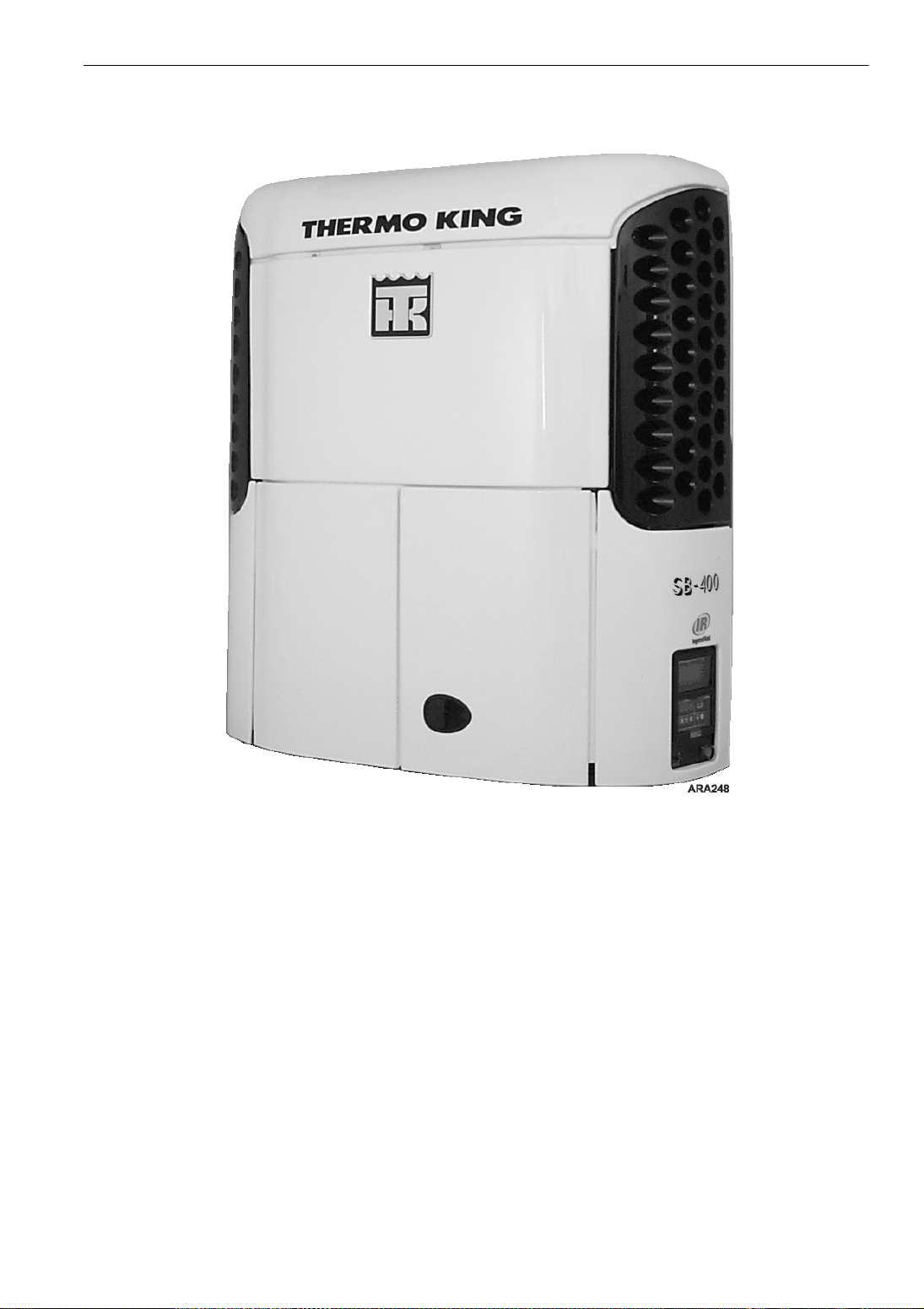
Unit Photos
Figure 4: Front View

Design Features and Unit Photos
20
1. Defrost Damper
2. S391 Compressor
3. TK 486 Engine
Figure 5: Back View
1
2
3
Table of contents
Popular Engine manuals by other brands


Hacker
Hacker A60 quick start guide

GEIGER
GEIGER SOLIDline ZIP-Perfection GU45 E11 Series Original assembly and operating instructions

Kohler
Kohler KT715 Service manual

O.S. engine
O.S. engine OMA-3825-750-W Owner's instruction manual

FeiaoModel
FeiaoModel DLA Series user manual

RCGF
RCGF 70CC-Twin Operator's manual


