Thermo King CSR40-149 User manual

CSR40-149 & -150
Power Saver
TK 50892-4-MM (Rev. 6/00)
Maintenance Manual
Copyright ©2000, Thermo King Corporation, Minneapolis, MN, U.S.A.
Printed in U.S.A.

This manual is published for informational purposes only and the information so provided should not be considered as all-inclusive
or covering all contingencies. If further information is required, Thermo King Corporation should be consulted.
Sale of product shown in this Manual is subject to Thermo King’s terms and conditions including, but not limited to, the THERMO
KING EXPRESS WARRANTY. Such terms and conditions are available upon request.
Thermo King’s warranty will not apply to any equipment which has been “so repaired or altered outside the manufacturer’s plants
as, in the manufacturer’s judgment, to effect its stability.”
No warranties, express or implied, including warranties of fitness for a particular purpose or merchantability, or warranties arising
from course of dealing or usage of trade, are made regarding the information, recommendations, and descriptions contained herein.
Manufacturer is not responsible and will not be held liable in contract or in tort (including negligence) for any special, indirect or con-
sequential damages, including injury or damage caused to vehicles, contents or persons, by reason of the installation of any
Thermo King product or its mechanical failure.
SmartSponge and Thermoguard are trademarks of Thermo King Corporation. All other trademarks are the property of their respec-
tive owners.

Recover Refrigerant
At Thermo King we recognize the need to preserve the environment and limit
the potential harm to the ozone layer that can result from allowing refrigerant
to escape into the atmosphere.
We strictly adhere to a policy that promotes the recovery and limits the loss
of refrigerant into the atmosphere.
In addition, service personnel must be aware of Federal regulations concern-
ing the use of refrigerants and the certification of technicians. For additional
information on regulations and technician certification programs, contact
your local THERMO KING dealer.


CSR40-149 & -150 PS Hermetic, June 2000
Introduction v
About This Manual v
Other Reference Manuals v
CSR40-149 & -150 PS Model Features vi
Safety Precautions vii
General Practices vii
Refrigerant vii
Refrigerant Oil viii
Electrical viii
General Safety Practices for Servicing Units
(or Containers) Equipped with a
Microprocessor Controller ix
Unit Decals x
Serial Number Locations x
Service Guide xi
Specifications 1-1
System Net Cooling Capacity — Full Cool:
CSR40 PS Models — Air Cooled Condensing 1-1
System Net Heating Capacity 1-1
Evaporator Airflow:
CSR40 PS Models 1-1
Electrical System 1-2
Refrigeration System 1-3
MP-3000 Controller 1-4
Dehumidify and Humidify Systems (Options) 1-5
Physical Specifications 1-6
Metric Hardware Torque Charts 1-7
Unit Description 2-1
Unit Features 2-1
Unit Options 2-2
Operating Modes 2-3
Unit Illustrations 2-4
Typical Unit Front View 2-4
Unit Options Front View 2-5
CSR40 PS Evaporator Section – Front View 2-6
Hermetic Refrigeration System 2-7
MP-3000 Controller 2-8
Unit Control Box 2-9
Humidify System Option 2-10
Advanced Fresh Air Management Option 2-11
Typical Unit Back View 2-12
Operating Instructions 3-1
Unit Controls 3-1
Unit Instruments 3-1
Unit Protection Devices 3-1
Pretrip Inspection 3-3
Starting the Unit and Adjusting the Controller
Setpoint 3-4
Loading Procedure 3-5
Post Load Procedure 3-5
Post Trip Procedure 3-5
MP-3000 Controller 4-1
Controller Description 4-1
Status Indicator LEDs 4-3
Data Recording and Downloading Data 4-3
General Theory of Operation 4-4
Chill Loads 4-4
Frozen Loads 4-5
Modulation Display in Data Menu 4-5
Power Limit Mode 4-5
Table of Contents

ii Table of Contents
CSR40-149 & -150 PS Hermetic, June 2000
Compressor Liquid Injection 4-5
Warm Gas Bypass 4-5
Evaporator Fan Control 4-5
Condenser Fan Control 4-6
Economy Mode Operation 4-6
Probe Test 4-6
Dehumidify Mode (Option) 4-7
Sequence of Operation 4-7
Unit Start-up 4-7
Continuous Temperature Control Operation 4-8
Operating Mode Function Chart — Standard
Operation 4-9
Operating Mode Function Chart — Optional
Feature Operation 4-10
Defrost 4-11
Changing the Setpoint 4-12
Initiating a Manual Defrost 4-12
Displaying Alternate Controlling (Supply or
Return) Air Sensor Temperature 4-12
Displaying Alternate Fahrenheit (F) or
Celsius (C) Temperatures 4-13
Navigating the Controller Menu 4-13
General Operating Tips 4-13
Setpoint Menu 4-13
Changing the Setpoint Temperature 4-13
Changing the Economy Mode Setting 4-14
Changing the Humidity Mode Setting 4-14
Changing the Humidity Setpoint 4-14
Changing the Advanced Fresh Air
Management (AFAM) Mode Setting 4-14
Changing the AFAM Delay 4-15
Changing the AFAM Rate 4-15
Data Menu 4-16
Viewing the Data Menu 4-16
Alarms Menu 4-16
Alarm Types 4-16
Alarm Code States 4-17
Viewing the Alarm List Menu 4-17
Alarm List 4-17
Commands Menu 4-18
View the Commands Menu 4-18
Defrost 4-19
Function Test 4-19
CSR PS Function Test Procedure 4-21
Pretrip (PTI) Test 4-20
CSR PS Pretrip (PTI) Test Procedure 4-23
Manual Function Test 4-20
Power Management 4-28
Misc. Functions Menu 4-28
Viewing the Misc. Functions Menu 4-28
Setting the Date and Time 4-28
Changing the Temperature Display
Value (C/F) 4-29
Setting Cargo Data 4-29
Viewing or Setting Run Time 4-30
Configuration Menu 4-30
Viewing or Setting Functions 4-30
Datalogger Menu 4-31
Viewing the Datalogger Menu 4-32
Inspect Temp Log 4-32
Inspect Event Log 4-32
Set Log Time 4-33
Set a Trip Start 4-33
Inspect PTI Log 4-34
RMM State Menu 4-34
Viewing the RMM State Screen 4-34
Manual Emergency Mode Operation 4-34
Replacing the Controller 4-35
Automatic Configuration of Spare
Parts Controller 4-35
Controller Software Selection 4-36
Flash Loading Controller Software 4-36
Temperature Sensors 4-36
Diagnosis and Repair 4-38
Error Messages and Controller Actions 4-39
Alarm Codes, Descriptions and
Corrective Actions 4-42 to 4-61
Electrical Maintenance 5-1
Unit Wiring 5-1
High Pressure Cutout Switch 5-1
Low Pressure Cutout Switch 5-2
Condenser Fan and Evaporator Fan Rotation 5-2
Electric Heaters 5-3

CSR40-149 & -150 PS Hermetic, June 2000
Table of Contents iii
Refrigeration System Diagnosis and Service 6-1
Hermetic Refrigeration System Diagnosis
Procedures 6-1
Hermetic Refrigeration System Visual Inspection
and Diagnosis Chart 6-3
Hermetic Refrigeration System Service
Procedures 6-4
Service Tools 6-4
Refrigerant Charge 6-5
Compressor Oil Charge 6-6
Installing and Removing Piercing Type Service
Valves and a Gauge Manifold Set 6-6
Gauge Manifold Valve Positions 6-8
Refrigerant Leak Test Procedure 6-9
Using Pressurized Nitrogen 6-9
Refrigerant Recovery from Hermetic
Refrigeration Systems 6-10
Evacuation and Cleanup of the
Refrigeration System 6-11
Charging the System with Refrigerant 6-15
Compressor Replacement 6-15
Compressor Discharge Temperature Sensor
Replacement 6-16
Stepper Motor Valve Replacement 6-17
Condenser Coil Replacement 6-17
Filter Drier/In-line Filter Replacement 6-18
Expansion Valve Replacement 6-18
Heat Exchanger Replacement 6-19
Receiver Tank Replacement 6-19
Low or High Pressure Cutout Switch Replacement 6-20
Warm Gas Bypass Solenoid Valve, Liquid
Injection Valve or Dehumidify Valve
(Option) Replacement 6-20
Structural/Accessory Maintenance 7-1
Mounting Bolts 7-1
Unit Inspection 7-1
Condenser Coil 7-1
Evaporator Coil 7-1
Defrost Drains 7-2
Condenser Fan Location 7-2
Evaporator Fan Location 7-2
Humidify System (Option) 7-2
Partlow (Model SR) Recording Thermometer
(Option) 7-3
Advanced Fresh Air Management (AFAM) System
(Option) 7-5
Mechanical Diagnosis 8-1
Mechanical Diagnosis 8-1
Electrical, Refrigeration and MP-3000 Menu Flow
Diagrams 9-1
Controller Diagram 9-3
Wiring Schematic 9-4
Main Relay Board Terminal Connections
(Page 1 of 3) 9-5
Main Relay Board Terminal Connections
(Page 2 of 3) 9-6
Main Relay Board Terminal Connections
(Page 3 of 3) 9-7
Refrigeration System Schematics:
Refrigeration System Components 9-8
Full Cool Flow and Pressure Diagram 9-9
Modulation Cool Flow and Pressure Diagram 9-10
Dehumidification Flow and Pressure Diagram 9-11
MP-3000 Menu Flow Diagram 9-12


CSR40-149 & -150 PS Hermetic, June 2000
Introduction
About This Manual
The information in this manual is provided to assist owners,
operators and service people in the proper upkeep and mainte-
nance of Thermo King units. This manual includes mainte-
nance and diagnosis information for both standard and option-
al unit features. Some optional features may not apply to your
unit. The maintenance information in this manual covers unit
models:
CSR PS Hermetic Models System Number
CSR40-149 Power Saver 917149
CSR40-150 Power Saver 917150
Other Reference Manuals
For detailed descriptions of our refrigeration systems or micro-
processor controllers, see the appropriate manual. For further
information refer to:
Operation, Diagnosis and Refrigeration Maintenance
Manuals
Diagnosing Thermo King Container
Refrigeration Systems TK 41166
Electrostatic Discharge (ESD)
Training Guide TK 40282
Evacuation Station Operation and Field
Application TK 40612
Tool Catalog TK 5955

vi CSR40-149 & -150 PS Model Features Introduction
CSR40-149 & -150 PS Hermetic, June 2000
CSR40-149 & -150 PS Model Features
– – Slimline Frame
X X Top Air Discharge
X X 460-380V/3Ph/60-50 Hz, 18.3 m (60 ft) Power Cable and Plug
X X Dual Voltage Feature: 15 kVA Autotransformer with 460-380V Power Receptacle and 230-190V/3Ph/60-50 Hz, 18.3 m
(60 ft) Power Cable and Plug
X X 25 Amp Main Power Circuit Breaker
X X Automatic Phase Selection Control
X X Hermetic Scroll Compressor w/4.48 kW (6.0 Hp) Motor
X X Hermetic Refrigeration System
X X Refrigerant R-404A w/Polyol Ester Compressor Oil (TK P/N 203-433)
X X Stepper Valve Capacity Control System
X X Compressor Liquid Injection System
X X Warm Gas Bypass Valve System
X X MP-3000 Microprocessor Controller with Integral Datalogger
– – Three (3) Evaporator Fans with 2-Speed Motors
X X Two (2) Evaporator Fans with 2-Speed Motors
X X Condenser Fan with 1-Speed Motor
– – Fresh Air Exchange System
X X AFAM — Advanced Fresh Air Management
– – Data Retrieval Receptacle, Standard (5-Pin Deutsch)
X X Data Retrieval Receptacle, 5-Pin Threaded Cannon
– – Data Retrieval Receptacle, 15-Pin RS232
– X Dehumidify Control
– X Humidity System
– – Pressure Gauge, Discharge
– – Pressure Gauge, Suction
X X Recorder, Partlow
– – Recorder, Saginomiya
– – Remote Monitoring Plug (4-Pin)
– – TRANSFRESH®Provision
– – TRANSFRESH®Purge Port
– – TRANSFRESH®System, Complete
– – Thermistor Lead
– – USDA Cold Treatment Temperature Recording
– – Water-Cooled Condenser-Receiver Tank
CSR40-149 PS
CSR40-150 PS
FEATURES
X = Included
MODEL

CSR40-149 & -150 PS Hermetic, June 2000
General Practices
1. ALWAYS WEAR GOGGLES OR SAFETY GLASSES.
Refrigerant liquid and battery acid can permanently dam-
age the eyes (see First Aid under Refrigerant Oil).
2. Never close the compressor discharge valve with the unit
in operation. Never operate the unit with the discharge
valve closed.
3. Keep your hands, clothing and tools clear of the fans
when the refrigeration unit is running. If it is necessary to
run the refrigeration unit with covers removed, be very
careful with tools or meters being used in the area.
4. Be sure the gauge manifold hoses are in good condition.
Never let them come in contact with a fan motor blade or
any hot surface.
5. Never apply heat to a sealed refrigeration system or con-
tainer.
6. Fluorocarbon refrigerants, in the presence of an open
flame or electrical arc, produce toxic gases that are severe
respiratory irritants capable of causing death.
7. Be sure all mounting bolts are tight and are the correct
length for their particular application.
8. Use extreme caution when drilling holes in the unit. The
holes may weaken structural components. Holes drilled into
electrical wiring can cause fire or explosion. Holes drilled
into the refrigeration system may release refrigerant.
9. Use caution when working around exposed coil fins. The
fins can cause painful lacerations.
10. Use caution when working with a refrigerant or refrigera-
tion system in any closed or confined area with a limited
air supply (for example, a trailer, container or in the hold
of a ship). Refrigerant tends to displace air and can cause
oxygen depletion, resulting in suffocation and possible
death.
11. Use caution and follow the manufacturer’s suggested
practices when using ladders or scaffolds.
Refrigerant
When removing any refrigerant from a unit, use a recovery
process that prevents or absolutely minimizes the refrigerant
that can escape to the atmosphere. Although fluorocarbon
refrigerants are classified as safe refrigerants when proper
tools and procedures are used, certain precautions must be
observed when handling them or servicing a unit in which they
are used. When exposed to the atmosphere in the liquid state,
fluorocarbon refrigerants evaporate rapidly, freezing anything
they contact.
First Aid
In the event of frost bite, the objectives of First Aid are to pro-
tect the frozen area from further injury, to warm the affected
area rapidly, and to maintain respiration.
• EYES: For contact with liquid, immediately flush eyes
with large amounts of water and get prompt medical atten-
tion.
• SKIN: Flush area with large amounts of lukewarm water.
Do not apply heat. Remove contaminated clothing and
shoes. Wrap burns with dry, sterile, bulky dressing to
protect from infection/injury. Get medical attention.
Wash contaminated clothing before reuse.
• INHALATION: Move victim to fresh air and use CPR or
mouth-to-mouth ventilation, if necessary. Stay with victim
until arrival of emergency medical personnel.
Safety Precautions

viii Refrigerant Oil Safety Precautions
CSR40-149 & -150 PS Hermetic, June 2000
Refrigerant Oil
Observe the following precautions when working with or
around refrigerant oil:
• Do not allow refrigerant oil to contact your eyes.
• Do not allow prolonged or repeated contact with skin or
clothing.
• To prevent irritation, you should wash thoroughly imme-
diately after handling refrigerant oil. Rubber gloves are
recommended when handling Polyol Ester based refriger-
ant oil.
First Aid
• EYES: Immediately flush eyes with large amounts of
water for at least 15 minutes while holding the eyelids
open. Get prompt medical attention.
• SKIN: Remove contaminated clothing. Wash thoroughly
with soap and water. Get medical attention if irritation
persists.
• INHALATION: Move victim to fresh air and restore
breathing if necessary. Stay with victim until arrival of
emergency personnel.
• INGESTION: Do not induce vomiting. Contact a local
poison control center or physician immediately.
Electrical
High Voltage
When servicing or repairing a refrigeration unit, the possibility
of serious or even fatal injury from electrical shock exists.
Extreme care must be used when working with a refrigeration
unit that is connected to a source of operating power, even if
the unit is not running. Lethal voltage potentials can exist at
the unit power cord, inside the control box, inside any high
voltage junction box, at the motors and within the wiring har-
nesses.
Precautions
1. Be certain the unit On/Off switch is turned OFF before
connecting or disconnecting the unit power plug. Never
attempt to stop the unit by disconnecting the power plug.
2. Be certain the unit power plug is clean and dry before
connecting it to a power source.
3. Use tools with insulated handles that are in good condi-
tion. Never hold metal tools in your hand if exposed,
energized conductors are within reach.
4. Do not make any rapid moves when working on high volt-
age circuits. If a tool or other object falls, do not attempt
to grab it. People do not contact high voltage wires on
purpose. It occurs from an unplanned movement.
5. Treat all wires and connections as high voltage until a
meter and wiring diagram show otherwise.
6. Never work alone on high voltage circuits on the refriger-
ation unit. Another person should always be standing by
in the event of an accident to shut off the refrigeration unit
and to aid a victim.
7. Have electrically insulated gloves, cable cutters and safety
glasses available in the immediate vicinity in the event of
an accident.
First Aid
IMMEDIATE action must be initiated after a person has
received an electrical shock. Obtain immediate medical assis-
tance if available.
The source of shock must be immediately removed by
either shutting down the power or removing the victim from
the source. If it is not possible to shut off the power, the wire
should be cut with either an insulated instrument (e.g., a wood-
en handled axe or cable cutters with heavy insulated handles)
or by a rescuer wearing electrically insulated gloves and safety
glasses. Whichever method is used, do not look at the wire
while it is being cut. The ensuing flash can cause burns and
blindness.
If the victim has to be removed from a live circuit, pull the
victim off with a non-conductive material. Use the victim’s
coat, a rope, wood, or loop your belt around the victim’s leg or
arm and pull the victim off. DO NOT TOUCH the victim.
You can receive a shock from current flowing through the vic-
tim’s body.
After separating the victim from power source, check
immediately for the presence of a pulse and respiration. If a
pulse is not present, start CPR (Cardio Pulmonary
Resuscitation) and call for emergency medical assistance. If a
pulse is present, respiration may be restored by using mouth-
to-mouth resuscitation, but call for emergency medical assis-
tance.
Low Voltage
Control circuits are low voltage (24 Vac and 12 Vdc). This
voltage potential is not considered dangerous, but the large
amount of current available (over 30 amperes) can cause
severe burns if shorted to ground.
Do not wear jewelry, watch or rings. These items can short
out electrical circuits and cause severe burns to the wearer.

CSR40-149 & -150 PS Hermetic, June 2000
Safety Precautions General Safety Precautions for Servicing Controllers ix
General Safety Precautions for Servicing
Units (or Containers) Equipped with a
Microprocessor Controller
Precautions must be taken to prevent electrostatic discharge
when servicing the MP-3000 microprocessor and related com-
ponents. If these precautionary measures are not followed, the
risk of significant damage to the electronic components of the
unit is possible.
The primary risk potential results from the failure to wear
adequate electrostatic discharge preventive equipment when
handling and servicing the controller. The second cause
results from electric welding on the unit and container chassis
without taking precautionary steps.
Controller Repair
When servicing the controller, it is necessary to ensure that
electrostatic discharges are avoided. Potential differences con-
siderably lower than those which produce a small spark from a
finger to a door knob can severely damage or destroy solid-
state integrated circuit components. The following procedures
must be rigidly adhered to when servicing these units to avoid
controller damage or destruction.
1. Disconnect all power to the unit.
2. Avoid wearing clothing that generates static electricity
(wool, nylon, polyester, etc.).
3. Do wear a static discharge wrist strap (TK P/N 204-622)
with the lead end connected to the controller's ground ter-
minal. These straps are available at most electronic equip-
ment distributors. DO NOT wear these straps with power
applied to the unit.
4. Avoid contacting the electronic components on the circuit
boards of the unit being serviced.
5. Leave the circuit boards in their static proof packing mate-
rials until ready for installation.
6. If a defective controller is to be returned for repair, it
should be returned in the same static protective packing
materials from which the replacement component was
removed.
7. After servicing the circuit board and any other circuits, the
wiring should be checked for possible errors before restor-
ing power.
Welding of Units or Containers
Whenever electric welding is to be performed on any portion
of the refrigeration unit, container or container chassis with the
refrigeration unit attached, it is necessary to ensure that weld-
ing currents are NOT allowed to flow through the electronic
circuits of the unit. These procedures must be rigidly adhered
to when servicing these units to avoid damage or destruction.
1. Disconnect all power to the refrigeration unit.
2. Disconnect all quick-disconnect wire harnesses from the
back of the controller.
3. If the unit is equipped with an Remote Monitor Modem
(RMM), disconnect all wire harnesses from the RMM.
4. Switch all of the electrical circuit breakers in the control
box to the OFF position.
5. Weld unit and/or container per normal welding proce-
dures. Keep ground return electrode as close to the area to
be welded as practical. This will reduce the likelihood of
stray welding currents passing through any electrical or
electronic circuits.
6. When the welding operation is completed, the unit power
cables, wiring and circuit breakers must be restored to
their normal condition.

Serial Number Locations
Electric Motors: Nameplate attached to the motor housing.
Compressor: Nameplate on front of the compressor.
Unit: Nameplate on unit frame in power cord storage compart-
ment.
MP-3000 Controller: Nameplate on back of controller.
x Unit Decals Safety Precautions
CSR40-149 & -150 PS Hermetic, June 2000
Unit Decals
Serial number decals, refrigerant type decals and warning
decals appear on all Thermo King equipment. These decals
provide information that may be needed to service or repair the
unit. Service technicians should read and follow the instruc-
tions on all warning decals.
Unit Nameplate Location
CSR40-149 & -150 PS Hermetic, June 2000
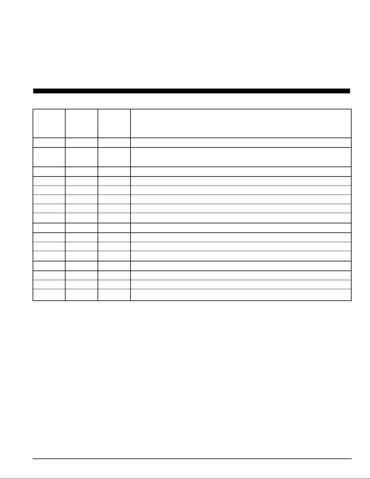
Service Guide
Every Annual/
1,000 Yearly
Pretrip Hours Inspect/Service These Items
Refrigeration
•Perform a controller Pretrip Inspection (PTI) test to check the refrigeration and electri-
cal systems.
Electrical
•••Visually inspect condenser fan and evaporator fan rotation.
•••Visually inspect electrical contacts for damage or loose connections.
•••Visually inspect wire harnesses for damaged wires or connections.
••
Download the data logger and check data for correct logging.
•Check operation of protection shutdown circuits.
Structural
•••
Visually inspect unit for damaged, loose or broken parts.
•••
Tighten unit, compressor and fan motor mounting bolts.
••
Clean entire unit including condenser and evaporator coils and defrost drains.
Humidify System (Option)
•Check water level in water tank.
•••
Check humidify system operation.
••
Clean water supply filter on water tank.


CSR40-149 & -150 PS Hermetic, June 2000
1 Specifications
System Net Cooling Capacity — Full Cool
Return air to 460/230V, 3 Phase, 60 Hz Power 380/190V, 3 Phase, 50 Hz Power
evaporator Net Cooling Capacity Power Consp Net Cooling Capacity Power Consp
coil inlet Watts Kcal/hr BTU/hr kW @460V Watts Kcal/hr BTU/hr kW @380V
21.1 C (70 F) 13,660 11,750 46,620 9.7 10,930 9,400 37,300 7.6
1.7 C (35 F) 10,090 8,680 34,440 8.9 8,070 6,940 27,545 6.9
-17.8 C (0 F) 5,945 5,115 20,290 6.0 4,755 4,090 16,230 5.4
-28.9 C (-20 F) 4,000 3,440 13,650 5.6 3,200 2,750 10,920 4.1
CSR40 PS Models — Air Cooled Condensing*
*System net cooling capacity with a 37.8 C (100 F) ambient air temperature and R-404A.
Heater Type 460/230V, 3 Phase, 60 Hz Power 380/190V, 3 Phase, 50 Hz Power
Heating Capacity Heating Capacity
Watts Kcal/hr BTU/hr Watts Kcal/hr BTU/hr
CSR40 PS 5,800 4,990 19,800 4,200 3,610 14,335
System Net Heating Capacity*
*System net heating capacity includes electric resistance rods and fan heat.
External Static 460/230V, 3 Phase, 60 Hz Power 380/190V, 3 Phase, 50 Hz Power
Pressure (water High Speed Low Speed High Speed Low Speed
column) m3/hr ft3/min m3/hr ft3/min m3/hr ft3/min m3/hr ft3/min
0 mm (0 in.) 6,560 3,860 3,170 1,865 5,480 3,225 2,710 1,595
10 mm (0.4 in.) 5,820 3,425 1,770 1,040 4,530 2,665 930 545
20 mm (0.8 in.) 5,000 2,940 — — 3,750 2,205 — —
30 mm (1.2 in.) 4,430 2,610 — — 2,930 1,725 — —
40 mm (1.6 in.) 3,520 2,070 — — 1,870 1,100 — —
CSR40 PS Models
Evaporator Airflow

1-2 Electrical System Specifications
CSR40-149 & -150 PS Hermetic, June 2000
Electrical System
Compressor Motor: Type 460/380V, 60/50 Hz, 3 Phase
Kilowatts 4.48 kW @ 460V, 60 Hz
Horsepower 6.0 hp @ 460V, 60 Hz
RPM 3550 rpm @ 460V, 60 Hz
Locked Rotor Amps 70 amps @ 460V, 60 Hz
Condenser Fan Motor: Type 460/380V, 60/50 Hz, 3 Phase
Kilowatts 0.37 kW @ 460V, 60 Hz
Horsepower 0.50 hp @ 460V, 60 Hz
RPM 1140 rpm @ 460V, 60 Hz
Full Load Amps 1.0 amps @ 460V, 60 Hz; 1.0 amps @ 380V, 50 Hz
Locked Rotor Amps 4.0 amps @ 460V, 60 Hz; 4.0 amps @ 380V, 50 Hz
Evaporator Fan Motors: Type 460/380V, 60/50 Hz, 3 Phase
Number: CSR40 PS 2
Kilowatts 0.75 kW @ 460V, 60 Hz
Horsepower 1.0 hp @ 460V, 60 Hz
RPM (Each): High Speed 3450 rpm @ 460V, 60 Hz
Low Speed 1725 rpm @ 460V, 60 Hz
Full Load Amps (Each): High Speed 1.1 amps @ 460V, 60 Hz
Low Speed 0.55 amps @ 460V, 60 Hz
Locked Rotor Amps: High Speed 10.3 amps @ 460V, 60 Hz
Low Speed 2.9 amps @ 460V, 60 Hz
Electric Resistance Heater Rods: Type 460/380V, 60/50 Hz, 3 Phase
Number 6
Watts (Each) 680 Watts @ 460V, 60 Hz
Current Draw (Amps) 5 amps total @ 460V across each phase at heater contactor
Control Circuit Voltage: 29 Vac @ 60 Hz
24 Vac @ 50 Hz
Advanced Fresh Air Management (AFAM) Motor:
Voltage 24 Vdc
Evaporator Overheat Switch: Opens 54 +/- 3 C (130 +/- 5 F)
Closes 38 +/- 4.5 C (100 +/- 8 F)

CSR40-149 & -150 PS Hermetic, June 2000
Specifications Refrigeration System 1-3
Refrigeration System
*When the compressor is removed from the unit, oil level should be noted or the oil removed from the compressor should be mea-
sured so that the same amount of oil can be maintained in the replacement compressor.
**DO NOT use or add standard synthetic or mineral oils to the refrigeration system. If Ester based oil becomes contaminated with
moisture or with standard oils, dispose of properly — DO NOT USE!
Compressor Model No.: ZM18K4E-TFD-279, Hermetic Scroll
Refrigerant Charge: CSR40 PS 3.6 Kg (8.0 lb) R-404A
Compressor Oil Capacity 1.77 liter (60 oz.)*
Compressor Oil Type Polyol Ester Based Type (required), TK Part No. 203-433**
High Pressure Cutout Switch: Cutout 3243 +/- 48 kPa, 32.43 +/- 0.48 bar, 470 +/- 7 psig
Cutin 2588 +/- 262 kPa, 25.88 +/- 2.62 bar, 375 +/- 38 psig
Low Pressure Cutout Switch: Cutout +21 to -20 kPa, +0.21 to -0.20 bar, 3 psig to 6” Hg vacuum
Cutin 48 to 90 kPa, 0.48 to 0.90 bar, 7 to 13 psig
High Pressure Relief Valve: Relief Pressure 3447 +520/-104 kPa, 34.47 +5.20/-1.04 bar, 500 +75/-15 psig
Reset 2758 kPa, 27.58 bar, 400 psig
Liquid Injection Control: Compressor Start Liquid injection valve opens for 5 minutes on each compressor start
Power Limit or Modulation Cool Liquid injection valve opens continuously during Power Limit and
Modulation Cool modes
Compressor Discharge Temperature Control Energizes (Opens) Liquid Injection Valve at 138 C (280 F)
De-energizes (Closes) Liquid Injection Valve at 132 C (270 F)
Compressor Shutdown (Auto Reset) at 148 C (298 F)
Liquid Injection Valve (Compressor): Voltage 24 Vac
Current 0.85 amps
Cold Resistance 5.6 ohms
Warm Gas Bypass Solenoid Valve: Voltage 24 Vac
Current 0.85 amps
Cold Resistance 5.6 ohms
Stepper Valve Regulating Motor: Voltage 12 Vdc
Current Draw 0.13 to 0.21 amperes per winding
0.26 to 0.44 amperes with 2 windings energized
Resistance 75 +/- 7.5 ohms across each winding at 24 C (75 F) ambient

MP-3000 Controller
Temperature Controller: Type MP-3000 microprocessor with thermostat, digital thermometer, pro-
gramming keypad, mode indicators, LED display and LCD display
for displaying unit operating and cargo information
Setpoint Range -29.0 to +29.0 C (-20.2 to +84.2 F)
Digital Temperature Display -60.0 to +80.0 C (-76.0 to +176.0 F)
Controller Software (Original Equipment): Version See controller identification decal
Defrost Initiation Evaporator Coil Sensor - Manual Switch or Demand Defrost Initiation: Coil must be below
18 C (65 F). Defrost cycle starts when technician or controller
request defrost initiation.
- Timed Defrost Initiation: Coil must be below 10 C (50 F).
Defrost cycle starts 1 minute after the hour immediately following
a defrost timer request for defrost initiation. For example, if the
defrost timer requests a defrost cycle at 7:35, the defrost cycle will
start at 8:01. Datalogger will record a Defrost event for each inter-
val in which a Defrost cycle is pending or active (i.e. both the 8:00
and 9:00 data logs).
Demand Defrost Demand defrost function initiates defrost when:
- Temperature difference between the return air sensor and defrost
(evaporator coil) sensor is too large
- Temperature difference between the supply air sensor and return
air sensor is too large
Defrost Timer: Chilled mode - Supply Temperature at 5.1 C (41.2 F) or Above: Every 8 hours of
compressor operation.
- Supply Temperature at 5.0 C (41.0 F) or Below: Every 2.5 hours
of compressor operation. Defrost interval increases 0.5 hours each
timed defrost interval. Defrost synchronization creates step inter-
vals of 3, 4, 4, 5, 5, 6, 6 and 7 hours. Maximum time interval in
chilled mode is 7 hours.
Defrost Timer: Frozen mode Every 8 hours of compressor operation. Defrost interval increases 2
hours each timed defrost interval. Maximum time interval in frozen
mode is 24 hours.
Defrost Timer: Reset to Base Time Defrost timer resets if the unit is Off more than 12 hours, setpoint is
changed more than 5 C (9 F) or PTI Pretrip test occurs.
1-4 MP-3000 Controller Specifications
CSR40-149 & -150 PS Hermetic, June 2000
This manual suits for next models
1
Table of contents
Other Thermo King Heat Pump manuals


