Thermo King CSR40SL-143 User manual

Maintenance Manual
Copyright ©2000, Thermo King Corporation, Minneapolis, MN, U.S.A.
Printed in U.S.A.
CSR40SL-143
Prepared for OOCL
TK 50836-4-MM (Rev. 2/00)

This manual is published for informational purposes only and the information so provided should not be considered as all-inclusive
or covering all contingencies. If further information is required, Thermo King Corporation should be consulted.
Sale of product shown in this Manual is subject to Thermo King’s terms and conditions including, but not limited to, the THERMO
KING EXPRESS WARRANTY. Such terms and conditions are available upon request.
Thermo King’s warranty will not apply to any equipment which has been “so repaired or altered outside the manufacturer’s plants
as, in the manufacturer’s judgment, to effect its stability.”
No warranties, express or implied, including warranties of fitness for a particular purpose or merchantability, or warranties arising
from course of dealing or usage of trade, are made regarding the information, recommendations, and descriptions contained herein.
Manufacturer is not responsible and will not be held liable in contract or in tort (including negligence) for any special, indirect or con-
sequential damages, including injury or damage caused to vehicles, contents or persons, by reason of the installation of any
Thermo King product or its mechanical failure.
Smart Reefer and Thermoguard are trademarks of Thermo King Corporation. All other trademarks are the property of their respec-
tive owners.

Recover Refrigerant
At Thermo King we recognize the need to preserve the environment and limit
the potential harm to the ozone layer that can result from allowing refrigerant
to escape into the atmosphere.
We strictly adhere to a policy that promotes the recovery and limits the loss
of refrigerant into the atmosphere.
In addition, service personnel must be aware of Federal regulations concern-
ing the use of refrigerants and the certification of technicians. For additional
information on regulations and technician certification programs, contact
your local THERMO KING dealer.


CSR40SL Semi-Hermetic, February 2000
Introduction v
About This Manual v
Other Reference Manuals v
CSR Semi-Hermetic Model Features vi
Safety Precautions vii
General Practices vii
Refrigerant vii
Refrigerant Oil viii
Electrical viii
General Safety Practices for Servicing Units
(or Containers) Equipped with a
Microprocessor Controller ix
Unit Decals x
Serial Number Locations x
Service Guide xi
Specifications 1-1
System Net Cooling Capacity – Full Cool 1-1
CSR40SL Models – Air Cooled Condensing 1-1
System Net Heating Capacity 1-1
Evaporator Airflow 1-1
CSR40SL Models 1-1
Electrical System 1-2
Refrigeration System 1-3
R-404A Temperature Pressure Relationships 1-4
Normal R-404A System Operating Pressures 1-5
Dehumidify System (Option) 1-5
Thermoguard®µP-D Controller 1-6
Physical Specifications 1-8
Metric Hardware Torque Charts 1-9
Unit Description 2-1
Unit Features 2-1
Unit Options 2-2
Operating Modes 2-2
Unit Illustrations 2-3 to 2-8
Typical Unit Front View 2-3
CSR40SL Evaporator Section — Front View 2-4
Semi-hermetic Refrigeration System 2-5
Scroll Compressor 2-6
Control Box – Door Open 2-7
Typical Unit Back View 2-8
Operating Instructions 3-1
Unit Controls 3-1
Unit Instruments 3-1
Unit Protection Devices 3-2
Pretrip Inspection 3-3
Starting the Unit and Adjusting the
Controller Setpoint 3-4
Loading Procedure 3-4
Post Load Procedure 3-4
Post Trip Procedure 3-4
µµP-D Controller 4-1
Controller Description 4-1
Controller Display Menus 4-3
Software Version Display 4-3
Active Option Displays 4-3
Pause Mode Displays 4-4
View Menu 4-4
Pretrip Menu 4-4
Test Menu 4-4
Guarded Access Menu 4-4
Program Menu 4-4
Menu Display Definitions 4-4
Table of Contents

ii Table of Contents
CSR40SL Semi-Hermetic, February 2000
Status Indicator LEDs and Alarm Codes 4-6
Pause Alarms 4-7
Data Logging and Downloading Data 4-8
General Theory of Operation 4-8
Chill Loads 4-8
Frozen Loads 4-9
Automatic Phase Selection 4-9
Compressor Liquid Injection 4-9
Modulation Valve Setting (PCVAL) 4-9
Evaporator Fan Control 4-9
Condenser Fan Control 4-9
Sensor Check 4-10
Power Limit 4-10
Economy Mode Operation 4-11
Sequence of Operation 4-11
Unit Start-up 4-11
Operating Mode Function Chart — Standard
Operation 4-12
Operating Mode Function Chart — Optional
Feature Operation 4-13
Continuous Temperature Control Operation 4-13
Defrost 4-16
Reviewing Software Version and Configuration 4-17
Displaying Alternate Fahrenheit (F) or
Celsius (C) Temperatures 4-17
Displaying Alternate Controlling (Supply or
Return) Air Sensor Temperatures 4-18
Changing the Setpoint 4-18
Initiating a Manual Defrost 4-19
Initiating a Full Pretrip 4-19
Entering a Start of Trip Marker 4-20
Displaying and Clearing Alarm Codes 4-20
Controller Menu Operating Instructions 4-21
Menu View Functions 4-21
Navigating the Menu View Screens 4-21
GRADE Submenu 4-22
LOG Submenu 4-22
Menu Pretrip Functions 4-25
Performing an Extended, Full or Single
Pretrip Test from the Pretrip Menu 4-26
Menu Test Functions 4-27
Menu Guard Functions 4-29
Navigating Menu Guard Screens 4-29
Setting the Unit Configuration and
Customer Configuration Numbers 4-30
Setting the Container Identification Number 4-30
Setting the Unit Serial Number 4-31
Setting the Time and Date 4-31
Setting the Compressor and On Time
Hourmeters 4-32
Setting the User Hourmeter Types, User
Hourmeter Thresholds and User
Hourmeters 4-32
Setting the Sensor Grades 4-33
Changing the Display Units (C/F) 4-35
Menu Program Functions 4-36
USDA Sensors 4-36
PULP Sensor (Option) 4-37
Economy Mode 4-38
Dehumidify Mode (Option) 4-39
Humidify Mode (Option) 4-39
Bulb Mode (Option) 4-40
Power Reduction Mode 4-41
Controller Emergency Bypass Procedure 4-42
Output Module 4-43
Thermo Bus Tap 4-43
Power Module 4-43
Replacing the µP-D Controller 4-44
Temperature Sensors 4-44
Diagnosis and Repair 4-45
Alarm Codes, Descriptions and
Corrective Actions 4-46 to 4-66
Electrical Maintenance 5-1
Unit Wiring 5-1
High Pressure Cutout Switch 5-1
Condenser Fan and Evaporator Fan Rotation 5-2
Electric Heaters 5-2

CSR40SL Semi-Hermetic, February 2000
Table of Contents iii
Refrigeration System Diagnosis and Service 6-1
Service Tools 6-1
Gauge Manifold Valve Positions 6-2
Gauge Manifold Set Attachment and Purging 6-2
Checking Compressor Oil 6-4
Refrigerant Charge 6-5
Refrigerant Leak Test Procedure 6-6
Using Pressurized Nitrogen 6-6
Refrigerant Recovery from Semi-hermetic
Refrigeration Systems 6-7
Evacuation and Cleanup of the
Refrigeration System 6-8
Charging the System with Refrigerant 6-12
Modulation Valve Repair or Replacement 6-12
Compressor Replacement 6-14
Condenser Coil Replacement 6-15
Filter Drier/In-line Filter Replacement 6-16
Expansion Valve Replacement 6-16
Heat Exchanger Replacement 6-17
Receiver Tank Replacement 6-17
High Pressure Cutout Switch, Condenser Fan
Speed Pressure Switch, or Compressor
Discharge Temperature Sensor Replacement 6-18
Warm Gas Bypass Valve, Liquid Injection Valve
or Dehumidify Valve (Option) Replacement 6-18
Structural/Accessory Maintenance 7-1
Mounting Bolts 7-1
Unit Inspection 7-1
Condenser Coil 7-1
Evaporator Coil 7-1
Defrost Drains 7-2
Fresh Air Exchange System 7-2
Evaporator Fan Location 7-2
Condenser Fan Location 7-3
Saginomiya (Model SKM) Recording Thermo-
meter (Option) 7-3
Battery 7-3
Recording Chart Replacement 7-4
Marking System Calibration 7-4
Power Element Assembly Replacement 7-4
Timer (Quartz Motor and Reducing Gear
Replacement 7-5
Battery Voltage Indicator 7-5
Diagnosis 8-1
Mechanical Diagnosis 8-1
Refrigeration Diagnosis 8-5
Electrical, Refrigeration and µµP-D Menu
Flow Diagrams 9-1
Electrical Schematic with Circuit Tracing 9-1
460/380 Vac Power Supply to Unit 9-1
External 12 Vdc Battery Power Supply 9-2
Microprocessor Awakened from Sleep Mode 9-3
12.5 Vdc Control Circuit, Sensor Circuits,
Modulation Valve Circuit and Water
Pressure Circuit (Option) 9-4
24 Vac Control Circuit 9-5
Dehumidify System, Humidify System,
Water Pressure Switch, USDA
Temperature Sensor, Pulp Sensor and
Chart Recorder Circuits (Options) 9-6
Cool Mode – Chill Load (Setpoint at -9.9 C
[14.1 F] or Above); Condenser Fan ON;
Power Monitor Limiting Unit Power
Consumption; Economy Mode OFF 9-7
Cool Mode – Chill Load (Setpoint at -9.9 C
[14.1 F] or Above); Condenser Fan ON;
Economy Mode OFF 9-8
Modulation Mode – Chill Load (Setpoint at
-9.9 C [14.1 F] or Above); Condenser
Fan ON; Economy Mode OFF;
Temperature Out-of-range 9-9
Modulation Mode – Chill Load (Setpoint at
-9.9 C [14.1 F] or Above); Condenser
Fan ON; Economy Mode OFF;
Temperature In-range; Dehumidify ON
with Humidity 1-5% Above Humidity
Setpoint 9-10
Modulation Mode – Chill Load (Setpoint at
-9.9 C [14.1 F] or Above); Condenser
Fan ON; Economy Mode OFF;
Temperature In-range; Dehumidify ON
with Humidity 5% or More Above
Humidity Setpoint 9-11
Modulation Mode – Chill Load (Setpoint at
-9.9 C [14.1 F] or Above); Condenser
Fan OFF; Economy Mode ON;
Temperature In-range 9-12

iv Table of Contents
CSR40SL Semi-Hermetic, February 2000
Modulation Mode – Chill Load (Setpoint at
-9.9 C [14.1 F] or Above); Condenser
Fan OFF; Economy Mode ON;
Temperature In-range; Warm Gas
Bypass Valve ON 9-13
Null Mode – Chill Load (Setpoint at -9.9 C
[14.1 F] or Above) Condenser Fan ON;
Economy Mode OFF 9-14
Heat Mode – Chill Load (Setpoint at -9.9 C
[14.1 F] or Above); Economy Mode
OFF; Temperature In-range 9-15
Cool Mode – Frozen Load (Setpoint at -10.0 C
[14.0 F] or Below); Condenser Fan ON;
Container Return Air Temperature Above
-10.0 C [14.0 F]; Power Monitor Limiting
Unit Power Consumption; Economy
Mode OFF 9-16
Cool Mode – Frozen Load (Setpoint at -10.0 C
[14.0 F] or Below); Condenser Fan ON;
Container Return Air Temperature Below
-10.0 C [14.0 F]; Economy Mode OFF;
Temperature In-range 9-17
Null Mode – Frozen Load (Setpoint at -10.0 C
[14.0 F] or Below) Condenser Fan OFF;
Economy Mode OFF 9-18
Null Mode – Frozen Load (Setpoint at -10.0 C
[14.0 F] or Below) Condenser Fan OFF;
Economy Mode ON 9-19
Defrost 9-20
CSR40SL Wiring Schematic 9-21
CSR40SL Wiring Diagram 9-22
Refrigeration System Schematics:
Refrigeration System Components 9-23
Full Cool Flow and Pressure Diagram 9-24
Modulation Cool Flow and Pressure Diagram 9-25
Dehumidification Flow and Pressure Diagram 9-26
µP-D Menu Flow Diagram 9-27

CSR-20 & CSR-40, October 1999
Introduction
About This Manual
The information in this manual is provided to assist owners,
operators and service people in the proper upkeep and mainte-
nance of Thermo King units. This manual includes mainte-
nance and diagnosis information for both standard and option-
al unit features. Some optional features may not apply to your
unit. The maintenance information in this manual covers unit
models:
CSR-40 PS Models System Number
CSR40SL-143 917143
Other Reference Manuals
For detailed descriptions of our refrigeration systems or micro-
processor controllers, see the appropriate manual or
Thermoguard µP-D Microprocessor Controller Diagnosis
Manual. For further information refer to:
Parts Manuals
CSR40-143 Parts List TK 50192
Operation, Diagnosis and Refrigeration Maintenance
Manuals
Diagnosing Thermo King Container
Refrigeration Systems TK 41166
Electrostatic Discharge (ESD)
Training Guide TK 40282
Evacuation Station Operation and Field
Application TK 40612
Tool Catalog TK 5955

vi CSR Semi-Hermetic Model Features Introduction
CSR40SL Semi-Hermetic, February 2000
X 460-380V/3Ph/60-50 Hz, 18.3 m (60 ft) Power Cable and Plug
– Dual Voltage Feature: 15 kVA Autotransformer with 460-380V Power Receptacle and 230-190V/3Ph/60-50 Hz, 18.3 m (60 ft)
Power Cable and Plug
X Automatic Phase Selection Control
X 25 Amp Main Power Circuit Breaker
X Slimline Frame
X Flanged Scroll Compressor w/4.48 kW (6.0 Hp) Motor
X Suction and Discharge Line Service Valves
X Compressor Liquid Injection System
X Warm Gas Bypass Valve System
X Modulation Valve
X Refrigerant R-404A w/Polyol Ester Compressor Oil (TK P/N 203-433)
X Receiver Tank with Two Moisture Indicating Sight Glasses
XµP-D Controller with Proportional-integral Differential (PID) Capacity Control
X Controller Emergency Bypass Module
X USDA Cold Treatment Temperature Recording
X Three Evaporator Fans with 2-Speed Motors
X Fresh Air Exchange System
XCO
2Sampling Port
X One 1-Speed Condenser Fan Motor
– Auxiliary Battery and Battery Charger
– Bulb Mode Operation
X Data Retrieval Receptacle, Standard (5-Pin Deutsch)
– Data Retrieval Receptacle, 5-Pin Threaded Cannon
– Data Retrieval Receptacle, 15-Pin RS232
X Dehumidify Control
– Humidity System
– Power Line Communications, Standard (Thermo King Modem)
– Power Line Communications, Thermo King Integrated Remote Monitor Unit (IRMU)
– Power Line Communications, RTE Modem
– Power Line Communications, Sabroe Control Modem
– Pressure Gauge, Discharge
– Pressure Gauge, Suction
– Recorder, Partlow
X Recorder, Saginomiya
– Remote Monitoring Plug (4-Pin)
– TRANSFRESH®Provision
– TRANSFRESH®Purge Port
– TRANSFRESH®System, Complete
– Thermistor Lead
– Water-Cooled Condenser-Receiver Tank
CSR40SL - 143
FEATURES
X = Included; O = Option
MODEL
CSR Semi-Hermetic Model Features

CSR40SL Semi-Hermetic, February 2000
General Practices
1. ALWAYS WEAR GOGGLES OR SAFETY GLASSES.
Refrigerant liquid and battery acid can permanently dam-
age the eyes (see First Aid under Refrigerant Oil).
2. Never close the compressor discharge valve with the unit
in operation. Never operate the unit with the discharge
valve closed.
3. Keep your hands, clothing and tools clear of the fans
when the refrigeration unit is running. If it is necessary to
run the refrigeration unit with covers removed, be very
careful with tools or meters being used in the area.
4. Be sure the gauge manifold hoses are in good condition.
Never let them come in contact with a fan motor blade or
any hot surface.
5. Never apply heat to a sealed refrigeration system or con-
tainer.
6. Fluorocarbon refrigerants, in the presence of an open
flame or electrical arc, produce toxic gases that are severe
respiratory irritants capable of causing death.
7. Be sure all mounting bolts are tight and are the correct
length for their particular application.
8. Use extreme caution when drilling holes in the unit. The
holes may weaken structural components. Holes drilled into
electrical wiring can cause fire or explosion. Holes drilled
into the refrigeration system may release refrigerant.
9. Use caution when working around exposed coil fins. The
fins can cause painful lacerations.
10. Use caution when working with a refrigerant or refrigera-
tion system in any closed or confined area with a limited
air supply (for example, a trailer, container or in the hold
of a ship). Refrigerant tends to displace air and can cause
oxygen depletion, resulting in suffocation and possible
death.
11. Use caution and follow the manufacturer’s suggested
practices when using ladders or scaffolds.
Refrigerant
When removing any refrigerant from a unit, use a recovery
process that prevents or absolutely minimizes the refrigerant
that can escape to the atmosphere. Although fluorocarbon
refrigerants are classified as safe refrigerants when proper
tools and procedures are used, certain precautions must be
observed when handling them or servicing a unit in which they
are used. When exposed to the atmosphere in the liquid state,
fluorocarbon refrigerants evaporate rapidly, freezing anything
they contact.
First Aid
In the event of frost bite, the objectives of First Aid are to pro-
tect the frozen area from further injury, to warm the affected
area rapidly, and to maintain respiration.
• EYES: For contact with liquid, immediately flush eyes
with large amounts of water and get prompt medical atten-
tion.
• SKIN: Flush area with large amounts of lukewarm water.
Do not apply heat. Remove contaminated clothing and
shoes. Wrap burns with dry, sterile, bulky dressing to
protect from infection/injury. Get medical attention.
Wash contaminated clothing before reuse.
• INHALATION: Move victim to fresh air and use CPR or
mouth-to-mouth ventilation, if necessary. Stay with victim
until arrival of emergency medical personnel.
Safety Precautions

viii Refrigerant Oil Safety Precautions
CSR40SL Semi-Hermetic, February 2000
Refrigerant Oil
Observe the following precautions when working with or
around refrigerant oil:
• Do not allow refrigerant oil to contact your eyes.
• Do not allow prolonged or repeated contact with skin or
clothing.
• To prevent irritation, you should wash thoroughly imme-
diately after handling refrigerant oil. Rubber gloves are
recommended when handling Polyol Ester based refriger-
ant oil.
First Aid
• EYES: Immediately flush eyes with large amounts of
water for at least 15 minutes while holding the eyelids
open. Get prompt medical attention.
• SKIN: Remove contaminated clothing. Wash thoroughly
with soap and water. Get medical attention if irritation
persists.
• INHALATION: Move victim to fresh air and restore
breathing if necessary. Stay with victim until arrival of
emergency personnel.
• INGESTION: Do not induce vomiting. Contact a local
poison control center or physician immediately.
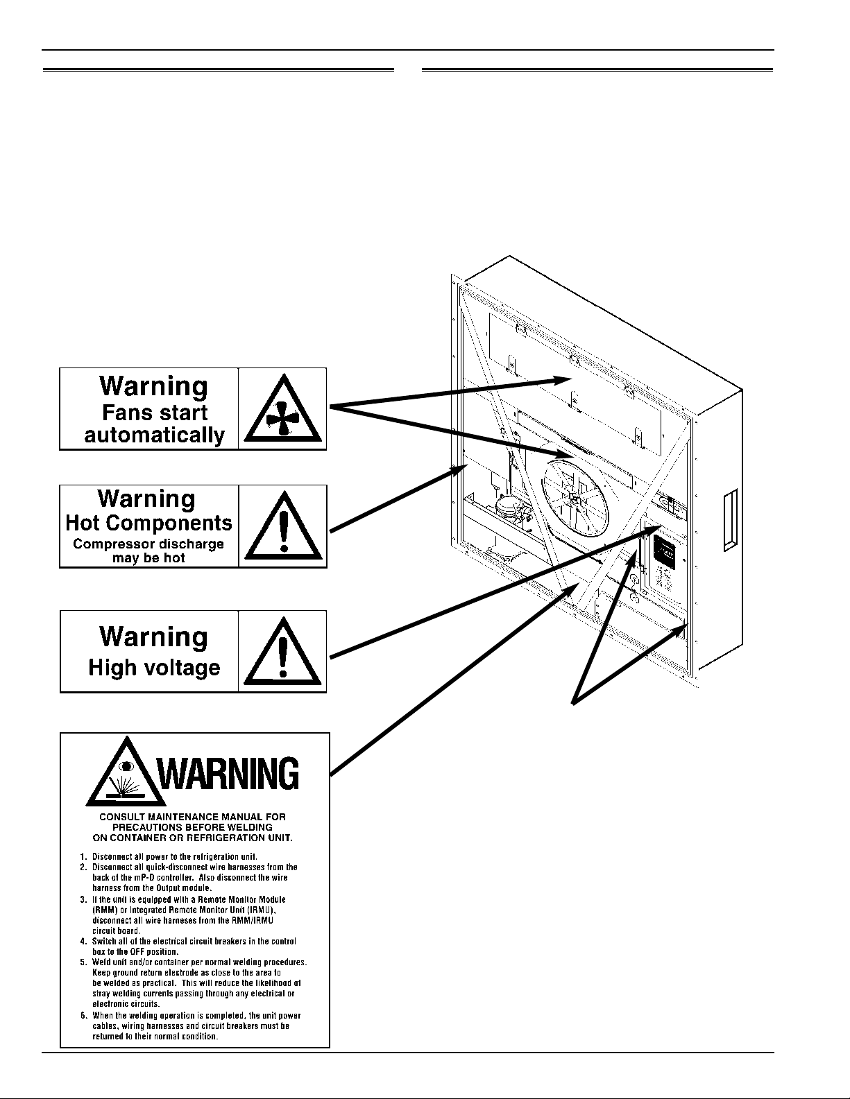
Electrical
High Voltage
When servicing or repairing a refrigeration unit, the possibility
of serious or even fatal injury from electrical shock exists.
Extreme care must be used when working with a refrigeration
unit that is connected to a source of operating power, even if
the unit is not running. Lethal voltage potentials can exist at
the unit power cord, inside the control box, inside any high
voltage junction box, at the motors and within the wiring har-
nesses.
Precautions
1. Be certain the unit On/Off switch is turned OFF before
connecting or disconnecting the unit power plug. Never
attempt to stop the unit by disconnecting the power plug.
2. Be certain the unit power plug is clean and dry before
connecting it to a power source.
3. Use tools with insulated handles that are in good condi-
tion. Never hold metal tools in your hand if exposed,
energized conductors are within reach.
4. Do not make any rapid moves when working on high volt-
age circuits. If a tool or other object falls, do not attempt
to grab it. People do not contact high voltage wires on
purpose. It occurs from an unplanned movement.
5. Treat all wires and connections as high voltage until a
meter and wiring diagram show otherwise.
6. Never work alone on high voltage circuits on the refriger-
ation unit. Another person should always be standing by
in the event of an accident to shut off the refrigeration unit
and to aid a victim.
7. Have electrically insulated gloves, cable cutters and safety
glasses available in the immediate vicinity in the event of
an accident.
First Aid
IMMEDIATE action must be initiated after a person has
received an electrical shock. Obtain immediate medical assis-
tance if available.
The source of shock must be immediately removed by
either shutting down the power or removing the victim from
the source. If it is not possible to shut off the power, the wire
should be cut with either an insulated instrument (e.g., a wood-
en handled axe or cable cutters with heavy insulated handles)
or by a rescuer wearing electrically insulated gloves and safety
glasses. Whichever method is used, do not look at the wire
while it is being cut. The ensuing flash can cause burns and
blindness.
If the victim has to be removed from a live circuit, pull the
victim off with a non-conductive material. Use the victim’s
coat, a rope, wood, or loop your belt around the victim’s leg or
arm and pull the victim off. DO NOT TOUCH the victim.
You can receive a shock from current flowing through the vic-
tim’s body.
After separating the victim from power source, check
immediately for the presence of a pulse and respiration. If a
pulse is not present, start CPR (Cardio Pulmonary
Resuscitation) and call for emergency medical assistance. If a
pulse is present, respiration may be restored by using mouth-
to-mouth resuscitation, but call for emergency medical assis-
tance.
Low Voltage
Control circuits are low voltage (24 Vac and 12 Vdc). This
voltage potential is not considered dangerous, but the large
amount of current available (over 30 amperes) can cause
severe burns if shorted to ground.
Do not wear jewelry, watch or rings. These items can short
out electrical circuits and cause severe burns to the wearer.

CSR40SL Semi-Hermetic, February 2000
Safety Precautions General Safety Precautions for Servicing Controllers ix
General Safety Precautions for Servicing
Units (or Containers) Equipped with a
Microprocessor Controller
Precautions must be taken to prevent electrostatic discharge
when servicing the µP-D microprocessor, output module and
related components. If these precautionary measures are not
followed, the risk of significant damage to the electronic com-
ponents of the unit is possible.
The primary risk potential results from the failure to wear
adequate electrostatic discharge preventive equipment when
handling and servicing the microprocessor. The second cause
results from electric welding on the unit and container chassis
without taking precautionary steps.
Controller Repair
When servicing the microprocessor, it is necessary to ensure
that electrostatic discharges are avoided. Potential differences
considerably lower than those which produce a small spark
from a finger to a door knob can severely damage or destroy
solid-state integrated circuit components. The following pro-
cedures must be rigidly adhered to when servicing these units
to avoid microprocessor damage or destruction.
1. Disconnect all power to the unit.
2. Avoid wearing clothing that generates static electricity
(wool, nylon, polyester, etc.).
3. Do wear a static discharge wrist strap (TK P/N 204-622)
with the lead end connected to the microprocessor’s
ground terminal. These straps are available at most elec-
tronic equipment distributors. DO NOT wear these straps
with power applied to the unit.
4. Avoid contacting the electronic components on the circuit
boards of the unit being serviced.
5. Leave the circuit boards in their static proof packing mate-
rials until ready for installation.
6. If a defective microprocessor is to be returned for repair, it
should be returned in the same static protective packing
materials from which the replacement component was
removed.
7. After servicing the circuit board and any other circuits, the
wiring should be checked for possible errors before restor-
ing power.
Welding of Units or Containers
Whenever electric welding is to be performed on any portion
of the refrigeration unit, container or container chassis with the
refrigeration unit attached, it is necessary to ensure that weld-
ing currents are NOT allowed to flow through the electronic
circuits of the unit. These procedures must be rigidly adhered
to when servicing these units to avoid damage or destruction.
1. Disconnect all power to the refrigeration unit.
2. Disconnect all quick-disconnect wire harnesses from the
back of the µP-D controller. Also disconnect the wire
harness from the Output module.
3. If the unit is equipped with a Remote Monitor Module
(RMM) or Integrated Remote Monitor Unit (IRMU), dis-
connect all wire harnesses from the RMM/IRMU circuit
board.
4. Switch all of the electrical circuit breakers in the control
box to the OFF position.
5. Weld unit and/or container per normal welding proce-
dures. Keep ground return electrode as close to the area to
be welded as practical. This will reduce the likelihood of
stray welding currents passing through any electrical or
electronic circuits.
6. When the welding operation is completed, the unit power
cables, wire harnesses and circuit breakers must be
restored to their normal condition.

Serial Number Locations
Electric Motors: Nameplate attached to the motor housing.
Compressor: Nameplate on front of the compressor.
Unit: Nameplate on unit frame in power cord storage compart-
ment.
µµP-D Controller: Nameplate on back of controller.
x Unit Decals Safety Precautions
CSR40SL Semi-Hermetic, February 2000
Unit Decals
Serial number decals, refrigerant type decals and warning
decals appear on all Thermo King equipment. These decals
provide information that may be needed to service or repair the
unit. Service technicians should read and follow the instruc-
tions on all warning decals.
Unit Nameplate Location

CSR40SL Semi-Hermetic, February 2000
Service Guide
Every Annual/
1,000 Yearly
Pretrip Hours Inspect/Service These Items
Electrical
•Perform a controller Full Pretrip Test to check the electrical and refrigeration systems.
••Perform a controller Extended Pretrip Test.
•••Visually check condenser fan and evaporator fan rotation.
•••Visually inspect electrical contacts for damage or loose connections.
•••Visually inspect wire harness for damaged wires or connections.
••Download the data logger and check data for correct logging.
•Check calibration of graded sensors.
Refrigeration
•••Check refrigerant charge.
•••Check compressor oil level.
••Check for proper discharge and suction pressures.
•Check filter drier/in-line filter for a restriction or corrosion.
Structural
•••Visually inspect unit for damaged, loose or broken parts.
•••Tighten unit, compressor and fan motor mounting bolts.
••Clean entire unit including condenser and evaporator coils and defrost drains.


CSR40SL Semi-Hermetic, February 2000
1 Specifications
Return air to 460/230V, 3 Phase, 60 Hz Power 380/190V, 3 Phase, 50 Hz Power
evaporator Net Cooling Capacity Power Consp Net Cooling Capacity Power Consp
coil inlet Watts Kcal/hr BTU/hr kW @460V Watts Kcal/hr BTU/hr kW @380V
21.1 C (70 F) 12,660 10,890 43,200 9.8 10,130 8,715 34,575 7.6
1.7 C (35 F) 9,100 7,825 31,050 8.9 7,280 6,260 24,845 6.9
-17.8 C (0 F) 5,300 4,555 18,075 6.1 4,240 3,645 14,470 4.9
-28.9 C (-20 F) 3,470 2,980 11,830 5.8 2,775 2,385 9,470 4.1
CSR40SL Models — Air Cooled Condensing*
*System net cooling capacity with a 37.8 C (100 F) ambient air temperature and R-404A.
System Net Cooling Capacity — Full Cool
Heater Type 460/230V, 3 Phase, 60 Hz Power 380/190V, 3 Phase, 50 Hz Power
Heating Capacity Heating Capacity
Watts Kcal/hr BTU/hr Watts Kcal/hr BTU/hr
CSR40SL 5,880 5,060 20,070 4,900 4,215 16,720
System Net Heating Capacity*
*System net heating capacity includes electric resistance rods and fan heat.
External Static 460/230V, 3 Phase, 60 Hz Power 380/190V, 3 Phase, 50 Hz Power
Pressure (water High Speed Low Speed High Speed Low Speed
column) m3/hr ft3/min m3/hr ft3/min m3/hr ft3/min m3/hr ft3/min
0 mm (0 in.) 5,820 3,430 2,800 1,650 4,860 2,860 2,590 1,525
10 mm (0.4 in.) 5,055 2,975 1,400 825 3,940 2,320 510 300
20 mm (0.8 in.) 4,365 2,570 — — 3,040 1,790 — —
30 mm (1.2 in.) 3,440 2,025 — — 2,140 1,260 — —
40 mm (1.6 in.) 2,615 1,540 — — — — — —
CSR40SL Models
Evaporator Airflow

1-2 Electrical System Specifications
CSR40SL Semi-Hermetic, February 2000
Electrical System
Compressor Motor: Type 460/380V, 60/50 Hz, 3 Phase
Kilowatts 4.48 kW @ 460V, 60 Hz
Horsepower 6.0 hp @ 460V, 60 Hz
RPM 3550 rpm @ 460V, 60 Hz
Locked Rotor Amps 70 amps @ 460V, 60 Hz
Condenser Fan Motor: Type 460/380V, 60/50 Hz, 3 Phase
Kilowatts 0.37 kW @ 460V, 60 Hz
Horsepower 0.50 hp @ 460V, 60 Hz
RPM 1145 rpm @ 460V, 60 Hz
Full Load Amps 0.9 amps @ 460V, 60 Hz; 1.0 amps @ 380V, 50 Hz
Locked Rotor Amps 4.0 amps @ 460V, 60 Hz; 4.0 amps @ 380V, 50 Hz
Evaporator Fan Motors: Type 460/380V, 60/50 Hz, 3 Phase
Number: CSR40SL 3
Kilowatts 0.75 kW @ 460V, 60 Hz
Horsepower 1.0 hp @ 460V, 60 Hz
RPM (Each): High Speed 3450 rpm @ 460V, 60 Hz
Low Speed 1725 rpm @ 460V, 60 Hz
Full Load Amps (Each): High Speed 1.2 amps @ 460V, 60 Hz
Low Speed 0.5 amps @ 460V, 60 Hz
Locked Rotor Amps: High Speed 10.3 amps @ 460V, 60 Hz
Low Speed 2.9 amps @ 460V, 60 Hz
Electric Resistance Heater Rods: Type 460/380V, 60/50 Hz, 3 Phase
Number 6
Watts (Each) 680 Watts @ 460V, 60 Hz
Current Draw (Amps) 5 amps total @ 460V across each phase at heater contactor
Control Circuit Voltage 24 Vac
Auxiliary Battery (Option) 12 Vdc, 7 or 12 amp hour

CSR40SL Semi-Hermetic, February 2000
Specifications Refrigeration System 1-3
Refrigeration System
***When the compressor is removed from the unit, oil level should be noted or the oil removed from the compressor should be
measured so that the same amount of oil can be maintained in the replacement compressor.
****DO NOT use or add standard synthetic or mineral oils to the refrigeration system. If Ester based oil becomes contaminated
with moisture or with standard oils, dispose of properly — DO NOT USE!
Compressor Model No.: ZM18K4E-TFD-276, Scroll
Refrigerant Charge: CSR40SL 4.1 Kg (9.0 lb) R-404A
Compressor Oil Capacity 1.77 liter (60 oz.)***
Compressor Oil Type Polyol Ester Based Type (required), TK Part No. 203-433****
High Pressure Cutout Switch: Cutout 3243 +/- 48 kPa, 32.43 +/- 0.48 bar, 470 +/- 7 psig
Cutin 2588 +/- 262 kPa, 25.88 +/- 2.62 bar, 375 +/- 38 psig
High Pressure Relief Valve: Relief Pressure 3447 +520/-104 kPa, 34.47 +5.20/-1.04 bar, 500 +75/-15 psig
Reset 2758 kPa, 27.58 bar, 400 psig
Liquid Injection Control: Compressor Start Liquid injection valve opens for 5 minutes on each compressor start
Power Limit or Modulation Cool Liquid injection valve opens continuously during Power Limit and
Modulation Cool modes
Compressor Discharge Temperature Control Energizes (Opens) Liquid Injection Valve at 138 C (280 F)
De-energizes (Closes) Liquid Injection Valve at 132 C (270 F)
Compressor Shutdown (Auto Reset) at 148 C (298 F)
Liquid Injection Valve (Compressor): Voltage 24 Vac
Current 0.85 amps
Cold Resistance 5.6 ohms
Warm Gas Bypass Solenoid Valve: Voltage 24 Vac
Current 0.85 amps
Cold Resistance 5.6 ohms
Modulation Valve: Voltage 12 Vdc
Current Draw 0 to 0.4 amperes, valve open
0.4 to 1.4 amperes, valve modulates to close
Above 1.4 amperes, valve closed
Resistance 7.6 ohms at 24 C (75 F) ambient

1-4 R-404A Temperature Pressure Relationship Specifications
CSR40SL Semi-Hermetic, February 2000
Temp. Temp.
oFoC kPa Bar Psig
-50 -45.6 0 0 0
-48 -44.4 6.2 0.06 0.9
-46 -43.3 13.8 0.14 2.0
-44 -42.2 18.6 0.19 2.7
-42 -41.1 24.8 0.25 3.6
-40 -40.0 31.0 0.31 4.5
-38 -38.9 37.9 0.38 5.5
-36 -37.8 44.8 0.45 6.5
-34 -36.7 52.4 0.52 7.6
-32 -35.6 60.0 0.60 8.7
-30 -34.4 68.3 0.68 9.9
-28 -33.3 76.5 0.77 11.1
-26 -32.2 84.8 0.85 12.3
-24 -31.1 93.8 0.94 13.6
-22 -30.0 102.7 1.03 14.9
-20 -28.9 112.4 1.12 16.3
-18 -27.8 122.0 1.22 17.7
-16 -26.7 132.4 1.32 19.2
-14 -25.6 142.7 1.43 20.7
-12 -24.4 153.8 1.54 22.3
-10 -23.3 164.8 1.65 23.9
-8 -22.2 176.5 1.77 25.6
-6 -21.1 188.2 1.88 27.3
-4 -20.0 200.6 2.01 29.1
-2 -18.9 213.1 2.13 30.9
0 -17.8 226.2 2.26 32.8
2 -16.7 240.0 2.40 34.8
4 -15.6 253.7 2.54 36.8
6 -14.4 268.2 2.68 38.9
8 -13.3 283.4 2.83 41.1
10 -12.2 298.6 2.99 43.3
12 -11.1 314.4 3.14 45.6
14 -10.0 331.0 3.31 48.0
16 -8.9 347.5 3.48 50.4
18 -7.8 364.8 3.65 52.9
20 -6.7 382.7 3.83 55.5
22 -5.6 400.6 4.01 58.1
24 -4.4 419.9 4.20 60.9
26 -3.3 439.2 4.39 63.7
28 -2.2 458.5 4.59 66.5
30 -1.1 479.2 4.79 69.5
32 0.0 499.9 5.00 72.5
34 1.1 521.3 5.21 75.6
36 2.2 543.3 5.43 78.8
38 3.3 566.1 5.66 82.1
40 4.4 589.5 5.90 85.5
42 5.6 613.7 6.14 89.0
44 6.7 637.8 6.38 92.5
46 7.8 663.3 6.63 96.2
48 8.9 688.8 6.89 99.9
50 10 715.0 7.15 103.7
Temp. Temp.
oFoC kPa Bar Psig
52 11.1 742.6 7.43 107.7
54 12.2 770.2 7.70 111.7
56 13.3 798.4 7.98 115.8
58 14.4 827.4 8.27 120.0
60 15.6 857.1 8.57 124.3
62 16.7 888.1 8.88 128.8
64 17.8 919.1 9.19 133.3
66 18.9 950.8 9.51 137.9
68 20 983.9 9.84 142.7
70 21.1 1017.0 10.17 147.5
72 22.2 1051.5 10.52 152.5
74 23.3 1086.6 10.87 157.6
76 24.4 1122.5 11.23 162.8
78 25.6 1159.1 11.59 168.1
80 26.7 1196.3 11.96 173.5
82 27.8 1234.9 12.35 179.1
84 28.9 1273.5 12.74 184.7
86 30 1313.5 13.14 190.5
88 31.1 1354.9 13.55 196.5
90 32.2 1396.2 13.96 202.5
92 33.3 1439.0 14.39 208.7
94 34.4 1482.4 14.82 215.0
96 35.6 1526.6 15.27 221.4
98 36.7 1572.1 15.72 228.0
100 37.8 1618.3 16.18 234.7
102 38.9 1665.1 16.65 241.5
104 40 1713.4 17.13 248.5
106 41.1 1763.1 17.63 255.7
108 42.2 1812.7 18.13 262.9
110 43.3 1863.7 18.64 270.3
112 44.4 1916.1 19.16 277.9
114 45.6 1969.2 19.69 285.6
116 46.7 2023.7 20.24 293.5
118 47.8 2078.8 20.79 301.5
120 48.9 2135.4 21.35 309.7
122 50 2192.6 21.93 318.0
124 51.1 2251.2 22.51 326.5
126 52.2 2311.2 23.11 335.2
128 53.3 2371.9 23.72 344.0
130 54.4 2433.9 24.34 353.0
132 55.6 2496.9 24.97 362.1
134 56.7 2561.5 25.62 371.5
136 57.8 2627.0 26.27 381.0
138 58.9 2693.2 26.93 390.6
140 60 2761.5 27.62 400.5
142 61.1 2830.4 28.30 410.5
144 62.2 2900.7 29.01 420.7
146 63.3 2972.4 29.72 431.1
148 64.4 3045.5 30.46 441.7
150 65.6 3120.0 31.20 452.5
R-404A Temperature Pressure Relationship — Vapor Pressure
Table of contents
Other Thermo King Heat Pump manuals
Popular Heat Pump manuals by other brands

Black & Decker
Black & Decker BDXBT53 instruction manual

Bard
Bard W18H2 installation instructions

Carrier
Carrier 38BQ Installation, Start-Up and Service Instructions

Smart Lifestyle
Smart Lifestyle SLA-R18-190D/N3A4 installation guide

Unical
Unical HP OWER 500 RK Installation and Servicing Manual

Oasis
Oasis ELITE AC9 Installation instructions manual

Daikin
Daikin RZQ100KV4A Removal Procedure

Atlantic
Atlantic alfea extensa Series Installation and operating manual

STIEBEL ELTRON
STIEBEL ELTRON WPL 07 ACS classic Operation and installation

Nobel
Nobel R290 Installation, maintenance & use instructions

York
York LX series Technical guide

CLIMAVENETA
CLIMAVENETA AW HT user manual