THERMOBILE C8 User manual

1
Thermobile Coolmobile CR
MOBILE HEAT PUMP
Cooling only : C8 & C17
Cooling & heating : CR17 & CR34
Features :
Compressors High Efficiency
Able to withstand ambient temperature, cooling
from 20°C to 45°C (R410A)
Optional EC fan for Cooling from 10°C to 45°C
Analogic Pressure Transducer
Phase sequence relay protected against re-
versed phases for 3 phase models
Room temperature sensor thermostat
Low noise level

2
© Copyright
All technical information in this manual as well as drawings and diagrams are our property and may not be reproduced
without our prior written permission.

3
EC declaration
We declare that the devices forming part of this manual complies with the directives 98/37 / EEC (Directive on the safety
of machinery), 73/23 / EEC (Low Voltage Directive), 89/336 / EEC (Directive on Electromagnetic Compatibility and
97/23 / EEC (Directive on pressure equipment).
The devices forming part of this manual complies with the harmonized standards EN12100-1 / 2 (Safety of machinery),
EN 60335-1 (Low Voltage), EN 60335-2 (Low Voltage), EN 61000-6-2 (Immunity) and EN 61000-6-3 (Emission).
Responsibility
This equipment is specifically used for what it has designed and produced. Any contractual liability of the manufacturer
is excluded in case of damage to people, animals or property as a result of errors in installation, adjustment, mainte-
nance and unsuitable jobs.
The devices must be fitted exclusively with original accessories. The manufacturer will not be held responsible for any
damage resulting from the use of an inappropriate accessory to the device.
The appliances must be installed by qualified professionals, in compliance with the regulations and decrees, and follo-
wing the instructions mentioned in this leaflet. References to norms, standards and guidelines cited in this document is
for informational purposes only and speak only as of the date of issue thereof.
The manufacturer is responsible for the compliance of the apparatus with the rules, directives and construction stan-
dards at the time of marketing. Knowledge and compliance with legal provisions and standards inherent in the design,
implementation, installation, commissioning and maintenance are the exclusive responsibility of the consulting firm, the
installer and the 'user.
Reception - Storage
The device is delivered on wooden pallets, protected by cardboard and / or plastic wrapping. It is essential to check the
status of the delivered material (even if the packaging is intact) and its compliance with the order.
In case of damage or missing parts, you should put the comments on the carrier's receipt of the most accurate way pos-
sible, "subject to unpacking" has no legal value, confirm these reservations by registered letter within 48 hours to the
carrier. Please remember that it is the responsibility of the buyer to check the goods delivered, no appeal will be pos-
sible if this procedure is not followed.
Store the devices in a clean, dry, protected from shock, vibration, temperature variations and a less than 90% humidity
atmosphere.
WARNING
When using a forklift, it must be ensured that the fork fully support the device, they must exceed at the opposite
side of their their entrance. handle with care ! A drop off can bring about permanent damage.

4
This technical manual must be kept in good condition inside the unit.
PLEASE READ BEFORE CONTINUING
Features, illustrations and descriptions contained herein are, to our knowledge, accurate at the time of appro-
val for printing. We reserve the right to change, to no longer offer certain features or to stop production of a
model without notice, and is not a commitment on our part.
Security rules
-Do not cover, stop up or obstruct the openings of the unit, this could cause malfunctions!
-Do not restart the compressor repeatedly within a short period of time may result in overheating and da-
mage to the compressor.
-Do not operate the equipment outside its recommended temperature range. Use of the product outside the
temperature range specified in the technical characteristics, can cause frequent restarts of the cooling system
which may damage it.
-Never make any changes to the settings that were performed by a qualified professional.
-Never touch the hot parts and / or moving parts.
-Do not place or hang anything on the unit.
-All work on the device is prohibited before having disconnected the power supply.
-Do not change the original settings, security or control, to the extent that it could create dangerous situa-
tions.
-In the case of a long period of non-operation, disconnect the power supply of the device. When putting into
operation, it is advisable to call in qualified personnel. Generally all repair work or maintenance should be
performed only by authorized and trained personnel.
Caution
Electrical components, running mechanisms can cause injury. To protect themselves from these risks during
installation or maintenance, power supply should be disconnected. Everyone involved in the installation or
maintenance of this equipment must respect the health and safety rules, and comply with the laws of the
country of use.
Before performing service or maintenance operaons on system, turn o main power switch of the unit.
Electrical shock could cause personal injury.
This unit shall be installed in accordance with naonal wiring regulaons.
If the supply cord is damaged, it must be replaced by the manufacturer or its service agent or similarly
qualied person in order to avoid a hazard.
The means for disconnecon from the supply having a contact separaon of at least 3 mm in all poles.
Recycling
This device uses R-410A refrigerant, before final disposal or performing maintenance operations, carefully
collect the fluid of that unit. Never reject in the environment, only use a compatible recovery equipment.
Please observe the national regulations and procedures to protect the environment

5
1-PRESENTATION AND OPERATION
This device is a mobile air conditioner for cooling demountable structures such as tents with a cooling capacity from 7
kW to 34 kW, depending of the model.
When the relative humidity of the air inlet is high, the air can be cooled below its dew point and humidity is then con-
densed to water. This process requires a certain amount of latent cooling but allows a dehumidification process, which is
an important factor in comfort for the user.
The operating range is between 20 and 45 ° C and is controlled by the HP / LP pressure. The drop in air temperature
depends on the conditions of entry (humidity).
The device are made with two compartment, isolated from each other. Its operation is based on a cooling circuit broken
down by two groups motorcycle fans.
The side of the device on which connect the ducts contain the evaporator. The fan sucks the warm indoor air, cool this
air through the exchanger and return it cold in the tent.
The opposite side contain the condenser. The fan draws in ambient outside air, it cross through the exchanger and re-
turns it outward.
The cooling system is filled with refrigerant R410a. This circuit is completely waterproof and allows the unit to operate in
areas with a maximum ambient temperature of +45 ° C.
At high ambient temperatures (above 45 ° C), the cooling of the condenser air flow is too low and a high pressure stops
the HP switch. The pressure switches HP / BP will reset automatically after a few minutes.
At an ambient temperature below 20 ° C, moisture in the airflow can form ice on the evaporator. To avoid this, the pres-
sure switch cuts the low pressure in the system. If the ambient temperature is too low, the BP activation causes frequent
starting and stopping of the compressor. This process can damage the compressor and should be avoided by always
using the product within the specified temperature range. See "Specifications".
Exchanger
(Condensor)
Exchanger
(Evaporator)
Temp. sensor
Evaporator
Temp. sensor
Condensor
Regulator
Liquid
phase
Gas
phase
Filter Compressor
To outdoor
To indoor
(Indoor) (Outdoor)
Compressor: Used to circulate the fluid in the cooling circuit
Filter: Absorbs moisture and impurities in the cooling circuit
Condenser: Sends the heat generated in the tent or room outwards
Regulator: Sends the amount of liquid that is right in the evaporator
Evaporator: Absorbs heat of the tent or room by cooling the air circulating
High pressure switch / BP: To ensure that the compressor does not work at a temperature too low or too high

6
2 GENERAL RULES FOR INSTALLATION
The installation configuration is an important factor in improving the performance and reliability of the air con-
ditioner. There are different ways to place the devices, here we give you some important recommendations.
2-1 Ducts
CAUTION: The ducts used are the same diameter as the connections of units. The junction between the diffe-
rent lengths must be watertight. The total length of the circuit should not exceed 6 meters per circuit (return
and supply). For longer length, please contact us.
Always use the least possible sheath. In general, think that every air duct 3m isolated changes the tempera-
ture inside the pipe by 5 ° C.
The sheaths result in a loss that's why we must always put straight, Fig.1. In case of deviation, avoiding signifi-
cant bends (bends> 45 °), Fig.2, prefer them large curves, fig.3.
Place the air distribution duct cooled as close to the ceiling, the cold air will descend slowly to the ground and
will be returned to the air conditioner through the air duct placed at the lowest, Fig.1.
2-2 Effect of the sun
The heating, due to solar effect reduces the efficiency of the air conditioner, heat builds up in the ducts and in
the tents it's greenhouse effect. We recommend installing a sunshade to cover the air conditioning, ducts and
the tent. It also becomes more effective if using panels/insulated coatings in the tent.
Fig.1
Fig.3Fig.2
Fig.1

7
2-3 Airflow
To cool the air effectively, the air sent to the air conditioner must be the lowest possible. If the ambient tempe-
rature is lower than outside temperature, it is more efficient to re-circulate the air from the tent. To do this, con-
nect the insulated ducts for blowing and sucking of air, between the tent and the air conditioner, fig.4.
If the temperature inside the tent is higher than the outside temperature, it may be advantageous to use the
device without air intake duct, fig.5. Attention in this case you risk introducing dust or increase pressure in the
tent.
2-4 Various
-Keep doors and openings of the tent/room closed when using the air conditioner.
-Avoid all heat generating sources in the air conditioned room.
-Do not cover, fig.6, or obstruct the rear of the air conditioner, fig.7. Keep a free and clear area for a good air
circulation allowing the correct operation of the conditioner, fig.8 & 9.
-If the air does not circulate well, the unit switches to safety. Poor repeated use causes irreversible damage.
-Always ensure that the exhaust ducts, fig.10, or air intake, fig.11, is not blocked or obstructed even partially.
If the air circulation is prevented the unit switches to safety. Poor repeated use causes irreversible damage.
-Accumulation of water produced by condensation, fig.12, disrupt the use of the
air conditioner, so we recommend that you raise the unit on a pallet for example,
or to evacuate the condensate to a remote area of the air conditioner.
Fig.4 Fig.5
Fig.6 Fig.7
OIL
OIL
Fig.8
1 m
1 m
2 m
2 m
1 m
Fig.9
Fig.10 Fig.11
Fig.12
8
C
ARACTÉRISTIQUES
TECHNIQUES
/ T
ECHNICAL
S
PECIFICATIONS
* The cooling capacity can change considerably depending on the humidity and air termperature.
** Optional EC Axial fan for cooling from 10°C instead of 20°C ambient temperature.
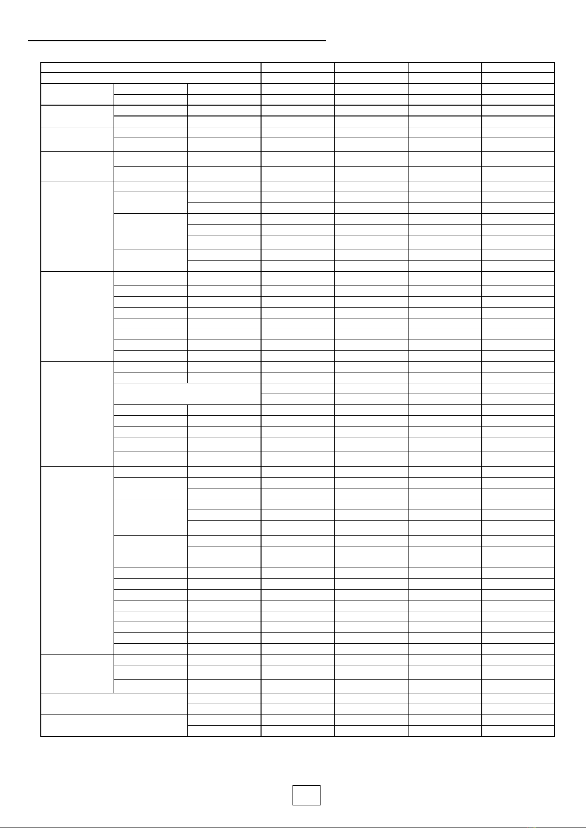
Nominal ton 2,2 4,8 4,8 9,5
Model C8C17 CR17 CR34
Capacity Cooling mode* Cooling Capacity Btu/h 28 000 58 000 58 000 111 000
W8 200 17 000 17 000 32 800
Capacity Heating mode* Heating Capacity Btu/h - - 58 000 111 000
W- - 20 000 32 800
Electrical data Power supply V-PH-Hz 230-1-50 380-3-50 380-3-50 380-3-50
Rated power Input W3 300 5 500 5 500 13 000
Performance
Air Circulation (High
speed) m3/h 1 500 4 500 4 500 7000
Indoor external static
pressure Pa 100 100 100 100
Indoor Coil
Number of rows 3333
Fin spacing mm 2,3 2,3 2,3 2
inch 3/32 3/32 3/32 3/32
Special
Grooved Tube Grooved Tube Grooved Tube Grooved Tube
Louvered fins Louvered fins Louvered fins Louvered fins
hydrophilic aluminum fins hydrophilic aluminum fins hydrophilic aluminum fins hydrophilic aluminum fins
Tube diameter mm Ф9.54 Ф9.54 Ф9.54 Ф9.54
inch 3/8 3/8 3/8 3/8
Indoor fan
Type Centrifugal Blower Centrifugal Blower Centrifugal Blower Centrifugal Blower
No. used 1112
Diameter mm Ф280mm Ф355mm Ф355mm Ф355mm
inch 11 14 14 14
Drive type DIRECT DIRECT DIRECT DIRECT
No. motors 1112
Motor output W240 315 315 315
Motor rpm r/min 2600 1780 1780 1 780
Compressor
Type Rotary Scroll Scroll Scroll
Quantity 1111
Model PA331X3CS C-SBP205H38 C-SBP205H38 C-SCP400H38
- - - -
Brand GMCC PANASONIC PANASONIC PANASONIC
Capacity Btu/hr 28 000 58 000 58 000 111 000
Input W3 300 5 500 5 500 11 000
Rated current(RLA) A13 10,3 10,3 20
Refrigerant oil charge TYPE - mL ESTER OIL VG74 · 1100 FV 68S - 1600 FV 68S - 1600 ‘
Outdoor Coil
Number of rows 2222
Fin spacing mm 1,8 1,8 1,8 2
inch 0,0709 0,0709 0,0709 0,0709
Special
Grooved Tube Grooved Tube Grooved Tube Grooved Tube
Louvered fins Louvered fins Louvered fins Louvered fins
hydrophilic aluminum fins hydrophilic aluminum fins hydrophilic aluminum fins hydrophilic aluminum fins
Tube diameter mm Ф9.54 Ф9.54 Ф9.54
inch 3/8 3/8 3/8 3/8
Outdoor Fan
Type Axial Axial Axial Axial
No. used 1111
Diameter mm Ф450 Ф630 Ф630 Ф800
inch 17,8 24,8 24,8 32
Drive type Direct Direct Direct Direct
No. motors 1111
Motor model ATE804S ATE808S ATE808S ATE810AP
Motor output W420 520 520 1 250
Motor rpm r/min 1350 900 900 700
Refrigerant
Type R410A R410A R410A R410A
Refrigerant volume kg 2,1 3,6 3,6 7,2
Refrigerant Control EEVX EEVX EEVX EEVX
Dimensions(W×H×D) mm 900x1150x1700 1200x1400x1800 1200x1400x1800 1200x2050x2250
inch 35x45x67 47x55x71 47x55x71 47x81x88
Net Weight kg 200 305 305 600
Ibs 386 672 672 1 322

9
Dimensions C8
Dimensions C17 & CR17

10
Dimensions CR34

11
CONTROL BOARD
The devices are equipped with a control panel with touch screen (1) of one general switch (2) and a
socket for connecting the room thermostat (3). The main power supply is connected to the cable
gland (4).
Control panel functions:
-View the status of the room thermostat, compressor and safety.
-Security Management High pressure
-Security Management Low pressure
-Security Management sub-cooling
-Security Management overheating
-Safety temperature management
-Controlling the cooling unit from room thermostat
-Viewing cooling unit values
A-Reset default
B-Page scrolling up
C-Page scrolling down
D– Valid
E-Idle display shows the status of the thermostat and the A/C unit.
1
2
4
3
ABCD
WAIT
THERMOSTAT OFF E

12
MENU DESCRIPTION
COMPRESSOR ON Everything is running ne, shown aer 20s of inacvity on the touchpad
HEATING
COMPRESSOR ON Everything is running ne, shown aer 20s of inacvity on the touchpad
COOLING
COMPRESSOR ON Unit is in defrost mode, shown aer 20s of inacvity on the touchpad
DEFROST Unit goes in defrost when heang and THP-TBP>55°C and Toudoor <9°C for 60 sec
HP 27,5/46,5/50/3,5 Shows High Pressure, Temperature of condensaon ( relave to pressure of refrigerant),
temperature of liquid on the outlet of the condenser, subcooling value
BP 7,2/-1/3/4 Shows Low Pressure, Temperature of evaporaon ( relave to pressure of refrigerant),
temperature of gas on the outlet of theevaporator,superheang value
P.HP 27,5 bar Shows High Pressure value
P.BP 7,2 bar Shows Low Pressure value
P.HP 27,5 bar Show High Pressure value
T.out Comp 50°C Show discharge temperature of compressor
T.out Cond 50°C Show value of the liquid refrigerant right on the outlet of the condenser
T.out Evap -3°C Show value of thegas refrigerant right on the outlet of the evaporator
SUBCOOLING 4°C
Show the value of the subcooling, that is equal to Temparature of condensaon minus liquid
temperature on the outlet of the condenser, ensure that expansion valve has 100% liquid
refrigerant
SUPHEATING 3,5°C
Show the value of the superheang, that is equal to Temparature of evaporaon minus gas
temperature on the outlet of the evaporator, ensures the sucon of the compressor is 100%
gaseous
INPUT AIR 25°C Shows temperature of air on the inlet of the indoor coil (return air from room)
OUTDOOR AIR 30°C Show temperature of outdoor air, sensor is placed on thegrill of the axial fan of the outside
heat exchanger.
COOLING 15H Shows how long the unit has been running on cooling mode, if the unit is capable of doing it
HEATING 10H Shows how long the unit has been running on heang mode, if the unit is capable of doing it
POS. VALVE 54% Shows current posion of the EEV (Electronic expansion valve)
SPEED FAN 100% Not in use right now
EER 4,85 Shows current EER in COOLING mode
P 17,0KW Shows output power based on extrapolaon (for informaon use only)
COP 3,85 Shows current COP in HEATING mode
P 17,0KW Shows output power based on extrapolaon (for informaon use only)

13
TROUBLESHOOTING
#1 WAIT TEMPO START Unit is waing to nish its safety me aer a cycle
360 SEC It is causes by restarng the unit too early, thermostat trigger, and aer a unit reset
#2 WAIT Thermostat is OFF or not in demand in either cooling or heang mode
REGULATION OFF
#3 OUTDOOR TOO LOW
Outdoor temperature is too low for the compressor to run in cooling mode : Min tempe-
rature to start 20°C, cut at 18°C ( start 10°C for EC axial version)
TEMPERATURE Outdoor temperature is too low for the compressor to run in heang mode : Min tempe-
#4 PHASE REVERSAL For three phases compressor, phases are not well connected
Reconnect the phase in the right order
#5 SENSOR PHP / ERROR Reconnect the sensor, check the high pressure sensor
#6 SENSOR PBP / ERROR Reconnect the sensor, check the low pressure sensor
#7 SENSOR T1 / ERROR Reconnect the compressor output temperature sensor, check the sensor
Check wire, replace the wire or check the sensor, replace the sensor
#8 SENSOR T2 / ERROR
Reconnect the temperature sensor right on the liquid side of the outdoor heat exchan-
ger , check the sensor
Check wire, replace the wire or check the sensor, replace the sensor
#9 SENSOR T3 / ERROR
Reconnect the temperature sensor right on the liquid side of the indoor heat exchanger ,
check the sensor
Check wire, replace the wire or check the sensor, replace the sensor
#10 SENSOR T4 / ERROR
Reconnect the temperature sensor right on the gas side of the indoor heat exchanger,
return to compressor , check the sensor
Check wire, replace the wire or check the sensor, replace the sensor
#11 SENSOR T5 / ERROR Reconnect the outdoor temperature sensor, check the sensor
Check wire, replace the wire or check the sensor, replace the sensor
#12 DEFAULT HP Temperature High pressure to high > 36 bar
PRESS RESET Need to press reset (round arrow)
#13 DEFAULT BP Temperature Low Pressure too low < 3,8 bar
PRESS RESET Need to press reset (round arrow)
#14 DEFAULT THP Temperature of discharge is too high >100°C
PRESS RESET Need to press reset (round arrow)

14
SCHEMA ELECTRIQUE /
ELECTRICAL WIRING
C8 (Cooling only) :

15
C8 (Cooling only) EC AXIAL FAN VERSION:

16
SCHEMA ELECTRIQUE /
ELECTRICAL WIRING
C17 (Cooling only) :

17
CR17 (Cooling and heating) :
SCHEMA ELECTRIQUE /
ELECTRICAL WIRING

18
CR17 (Cooling and heating) :

19
COMPONENTS:
LIST OF COMPONENTS
Item
1OUTDOOR HEAT EXCHANGER
2TOUCHPAD PCB
3PCB
4SAFETY SWITCH
5CONTACTOR
6THERMOSTAT IN
7FOUR WAY VALVE
8OUTDOOR AXIAL FAN
9LOW PRESSURE TRANSDUCER
10 SUCTION SIDE TEMPERATURE SENSOR
11 HIGH PRESSURE TRANSDUCER
12 SCHRADRE VALVE HIGH SIDE
13 OUTDOOR HEAT EXCHANGER TEMPERATURE SENSOR
14 FILTER
15 OUT COMPRESSOR TEMPERATURE SENSOR
16 COMPRESSOR
17 SCHRADRE VALVE LOW SIDE
18 INDOOR HEAT EXCHANGER TEMPERATURE SENSOR
19 ELECTRONIC EXPANSION VALVE
20 INDOOR HEAT EXCHANGER
21 INDOOR CENTRIFUGAL FAN
This manual suits for next models
3
Table of contents
Popular Heat Pump manuals by other brands

evoheat
evoheat EVO FLEX 10 Installation & operation manual

Heatcraft
Heatcraft CENTURION installation instructions

Solaris
Solaris SunPump MACHRW010W Installation instructions manual

Steinbach
Steinbach Waterpower 8500 Quick instruction guide

Bosch
Bosch MDCI10-1 owner's manual

Nordic
Nordic R-Series Installation and service manual


AWG
AWG SWIMSMART HEAT PUMPS SS110 owner's manual

eneren
eneren ENW Series user manual

CLIMAVENETA
CLIMAVENETA i-KI MTD Installation - user - maintenance manual

Fujitsu
Fujitsu WPYA100LA Service manual

Lennox
Lennox VPB H4-3P Series Installation & operation instructions

ClimateMaster
ClimateMaster Tranquility 30 Digital TE Series Installation operation & maintenance