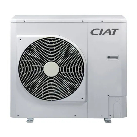
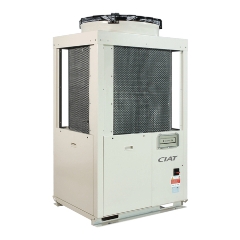
CIAT AQUACIAT POWER ILD Series User manual

AQUACIATPOWER ILD
11 - 2018
10145
Instruction manual

CONTENTS
1 - INTRODUCTION...................................................................................................................................................................... 4
1.1 - Safety considerations related to protection devices............................................................................................................ 4
1.2 - Refrigerant safety considerations........................................................................................................................................ 5
1.3 - Installation safety considerations ........................................................................................................................................ 6
1.4 - Maintenance safety considerations..................................................................................................................................... 7
1.5 - Safety considerations during system interventions ............................................................................................................. 7
2 - RECEIPT OF GOODS ............................................................................................................................................................. 9
2.1 - Check equipment received.................................................................................................................................................. 9
3 - HANDLING AND POSITIONING ........................................................................................................................................... 10
3.1 - Handling ............................................................................................................................................................................ 10
3.2 - Positioning......................................................................................................................................................................... 10
4 - DIMENSIONS, CLEARANCES...............................................................................................................................................11
4.1 - AQUACIATPOWER ILD ST / HE 602-900..............................................................................................................................11
4.2 - AQUACIATPOWER ILD ST / HE 902-1200........................................................................................................................... 12
4.3 - AQUACIATPOWER ILD ST / HE 1400-2000......................................................................................................................... 13
4.4 - Installing several units....................................................................................................................................................... 14
4.5 - Distance to the wall ........................................................................................................................................................... 14
5 - PHYSICAL AND ELECTRICAL DATA FOR THE UNITS...................................................................................................... 15
5.1 - Physical characteristics..................................................................................................................................................... 15
5.2 - Electrical data notes.......................................................................................................................................................... 19
5.3 - Short circuit current withstand capability........................................................................................................................... 20
5.4 - Electrical data notes for the hydronic module ................................................................................................................... 20
5.5 - Electrical data notes for the compressors ......................................................................................................................... 22
5.6 - Distribution of compressors per circuit .............................................................................................................................. 22
5.7 - Comments on electrical data notes................................................................................................................................... 23
6 - ELECTRICAL CONNECTION ............................................................................................................................................... 24
6.1 - Power supply..................................................................................................................................................................... 24
6.2 - Voltage phase imbalance (%)............................................................................................................................................ 24
6.3 - Recommended cable sections .......................................................................................................................................... 24
6.4 - Power cable access routing .............................................................................................................................................. 25
6.5 - Field-installed control wiring.............................................................................................................................................. 26
6.6 - Electric power reserve for the user.................................................................................................................................... 26
6.7 - Power connection/disconnect switch................................................................................................................................. 26
7 - APPLICATION DATA ............................................................................................................................................................. 27
7.1 - Operating range ................................................................................................................................................................ 27
7.2 - Minimum heat transfer uid ow rate (units without factory-tted hydronic module)......................................................... 28
7.3 - Maximum heat transfer uid ow rate (without factory-tted hydronic module) ................................................................ 28
7.4 - Variable ow evaporator (units without factory-tted hydronic module) ............................................................................ 28
7.5 - Water exchanger minimum water volume and ow rate ................................................................................................... 29
7.6 - Maximum system water volume........................................................................................................................................ 29
7.7 - Pressure drop curves for the water exchanger and standard water inlet/outlet piping ..................................................... 30
8 - WATER CONNECTIONS ....................................................................................................................................................... 31
8.1 - Operating precautions and recommendations .................................................................................................................. 31
8.2 - Water connections............................................................................................................................................................. 32
8.3 - Cavitation protection (with hydronic option) ...................................................................................................................... 34
8.4 - Flow rate detection............................................................................................................................................................ 34
8.5 - Frost protection ................................................................................................................................................................. 34
8.6 - Auxiliary electrical heaters................................................................................................................................................. 35
9 - NOMINAL SYSTEM WATER FLOW CONTROL................................................................................................................... 36
9.1 - Units without hydronic module .......................................................................................................................................... 36
9.2 - Units with hydronic module and xed speed pump........................................................................................................... 36
9.3 - Units with hydronic module and variable speed pump – Pressure differential control ...................................................... 37
9.4 - Units with hydronic module and variable speed pump – Temperature differential control ................................................ 38
9.5 - Units with hydronic module and variable speed pump – Setting a xed ow for the system ............................................ 38
9.6 - Available static pressure for the installation ...................................................................................................................... 39
10 - SYSTEM START-UP............................................................................................................................................................ 44
10.1 - Checks before system start-up........................................................................................................................................ 44
10.2 - Commissioning................................................................................................................................................................ 44
10.3 - Essential points to check................................................................................................................................................. 45
Translation of the original document
AQUACIATPOWER ILD EN-2

CONTENTS
11 - MAIN COMPONENTS OF THE UNIT AND OPERATING CHARACTERISTICS................................................................ 46
11.1 - Compressors ................................................................................................................................................................... 46
11.2 - Lubricant.......................................................................................................................................................................... 46
11.3 - Air-cooled exchanger....................................................................................................................................................... 46
11.4 - Fans................................................................................................................................................................................. 46
11.5 - Electronic expansion valve (EXV) ................................................................................................................................... 47
11.6 - Moisture indicator ............................................................................................................................................................ 47
11.7 - Refrigerant accumulator with lter drier........................................................................................................................... 47
11.8 - Water-cooled heat exchanger.......................................................................................................................................... 47
11.9 - Refrigerant....................................................................................................................................................................... 47
11.10 - HP safety pressostat ..................................................................................................................................................... 47
11.11 - Frequency inverter......................................................................................................................................................... 47
11.12 - Fan arrangement ........................................................................................................................................................... 48
11.13 - Fan stages..................................................................................................................................................................... 49
11.14 - Variable speed ventilation.............................................................................................................................................. 49
11.15 - Tank ............................................................................................................................................................................... 49
11.16 - 4-way valve.................................................................................................................................................................... 49
11.17 - Electrical box ................................................................................................................................................................. 49
11.18 - Connect Touch control................................................................................................................................................... 49
12 - OPTIONS ............................................................................................................................................................................. 50
12.1 - Tables of options ............................................................................................................................................................. 50
12.2 - Description ...................................................................................................................................................................... 52
13 - STANDARD MAINTENANCE.............................................................................................................................................. 64
13.1 - Level 1 maintenance ....................................................................................................................................................... 64
13.2 - Level 2 maintenance ....................................................................................................................................................... 64
13.3 - Level 3 maintenance ....................................................................................................................................................... 65
13.4 - Tightening of the electrical connections .......................................................................................................................... 65
13.5 - Tightening t orques for the main fastenings .................................................................................................................... 65
13.6 - Air-cooled exchanger....................................................................................................................................................... 65
13.7 - Water-cooled heat exchanger ......................................................................................................................................... 66
13.8 - Frequency inverter .......................................................................................................................................................... 66
13.9 - Refrigerant volume.......................................................................................................................................................... 66
13.10 - Refrigerant properties.................................................................................................................................................... 67
13.11 - Power factor correction.................................................................................................................................................. 67
14 - FINAL SHUTDOWN............................................................................................................................................................. 68
14.1 - Shutting down.................................................................................................................................................................. 68
14.2 - Recommendations for disassembly ................................................................................................................................ 68
14.3 - Fluids to be recovered for treatment ............................................................................................................................... 68
14.4 - Materials to be recovered for recycling ........................................................................................................................... 68
14.5 - Waste electrical and electronic equipment (WEEE)........................................................................................................ 68
15 - UNIT START-UP CHECKLIST FOR INSTALLERS PRIOR TO CONTACTING
THE MANUFACTURER .............................................................................................................................................................. 69
The illustrations in this document are for illustrative purposes only and not part of any offer for sale or contract. The manufacturer reserves the right to change the design
at any time without notice.
EN-3 AQUACIATPOWER ILD

1 - INTRODUCTION
The units are intended to cool or heat water for building air
conditioning or heating, or for industrial processes.
They are designed to provide a very high level of safety and
reliability, making installation, start-up, operation and maintenance
easier and safer.
They will provide safe and reliable service if used within their
application ranges.
They are designed to offer a service life of 15 years, assuming
a utilisation factor of 75%, which corresponds to approximately
100,000 operating hours.
Prior to the initial start-up of the units, everyone involved in the
works should be thoroughly familiar with these instructions and
with the characteristics of the installation site, and ensure these
are respected.
The procedures in this manual are arranged in the sequence
required for installation, start-up, operation and maintenance of
the units. Ensure that you follow them and that you take the
required safety precautions, including those listed in this guide,
which include wearing personal protective equipment (gloves,
safety glasses, safety shoes) and having the appropriate tools,
skills and qualifications (electrical, air conditioning, local
legislation).
To nd out if these products comply with European directives
(machine safety, low-voltage, electromagnetic compatibility,
pressurised equipment, etc.) check the declarations of conformity
for these products.
1.1 - Safety considerations related to
protection devices
Do not obstruct any protective devices.
This applies to any fusible plugs, rupture disks and valves tted
on the refrigerant or heat-transfer uid circuits. Check whether
the original protection plugs are still present at the valve outlets.
These plugs are generally made of plastic and should not be
used. If they are still present, please remove them. Fit devices
at the valve or discharge piping outlets to prevent the penetration
of foreign bodies (dust, building debris, etc.) and atmospheric
agents (water can form rust or ice). These devices, as well as
the discharge piping, must not impair operation and not lead to
a pressure drop that is higher than 10% of the set pressure.
Classication and control:
In accordance with the Pressure Equipment Directive and
national usage monitoring regulations in the European Union,
the protective devices tted to these machines are classied as
follows:
Safety device(1) Device for limitation of damage in
the event of an external re(2)
Refrigerant side
High pressure switch X
External relief valve(3) X
Rupture disk X
Fusible plug X
Heat transfer uid side
External relief valve (4) (4)
(1) Classied for protection in normal service situations.
(2) Classied for protection in abnormal service situations. These accessories
are sized for res with a thermal ow of 10kW/m². No combustible matter
should be placed within 6.5m of the unit.
(3) The instantaneous over-pressure limitation of 10% of the operating pressure
does not apply to this abnormal service situation.
The set pressure can be higher than the operating pressure. In this case,
either the design temperature or the high pressure switch ensures that the
operating pressure is not exceeded in normal service situations.
(4) The classication of these relief valves must be made by the personnel
responsible for completing the hydraulic installation.
Do not remove valves / fusible plugs, even if the re risk is under
control for a particular installation. There is no guarantee that
the accessories have been re-installed if the system is changed
or for transport with a gas charge.
When the unit is subjected to re, a safety device prevents rupture
due to over-pressure by releasing the refrigerant. The uid can
then break down into toxic residues when in contact with ames:
-Stay away from the unit;
-Ensure the personnel in charge of extinguishing the re are
duly warned and issued with recommendations;
-Fire extinguishers appropriate to the system and the
refrigerant type must be easily accessible.
All factory-tted relief valves are lead-sealed to prevent any
calibration change.
The external relief valves must always be vented to outside if
the units are installed in a closed space. Refer to the installation
regulations, for example those of European standard EN 378
and EN 13136. These pipes must be installed in a way that
ensures that people and property are not exposed to vented
refrigerant. As the uids can be diffused in the air, ensure that
refrigerant is discharged away from building air intakes, relief
valves must be checked periodically. The valves must be checked
periodically.
If the relief valves are factory-tted on a changeover valve, this
is equipped with a relief valve on each of the two outlets. Only
one of the two relief valves is in operation, the other one is
isolated. Never leave the changeover valve in the intermediate
position, i.e. with both circuits open (move the lever fully forwards
or backwards depending on the output to be isolated). If a valve
is removed for checking or replacement, make sure there is still
a valve active on each of the changeover valves installed on the
unit.
Provide a drain in the discharge pipework, close to each relief
valve, to avoid an accumulation of condensate or rain water.
It is recommended to install an indicating device to check whether
any refrigerant has leaked from the relief valve.
The presence of oil at the outlet orice is a useful indicator that
refrigerant has leaked. Keep this orice clean to ensure that any
leaks are obvious. The calibration of a valve that has leaked is
generally lower than its original calibration. The new calibration
may affect the operating range. To avoid nuisance tripping or
leaks, replace or re-calibrate the valve.
AQUACIATPOWER ILD EN-4

1 - INTRODUCTION
Protective device checks:
If no national regulations exist, check the protective devices on
site in accordance with standard EN378: once a year for the high
pressure switches, every ve years for the external relief valves.
The company or organisation that conducts a pressure switch
test must establish and implement detailed procedures for:
-Safety measures,
-Measuring equipment,
-Values and tolerances for cut-off and discharge devices,
-Test stages,
-Recommissioning of the equipment.
The principle for performing a test without disassembly of the
pressure switch is given here, however the manufacturer
recommends contacting the Service for this type of test:
-Verify and record the setpoints of pressure switches and
external relief devices (valves and possible rupture disks),
-Be ready to switch off the main disconnect switch of the power
supply if the pressure switch does not trigger (avoid over-
pressure or excess gas if there are valves on the high pressure
side on the recovery air exchangers, for example),
-Connect a calibrated pressure differential gauge with integral
damping (oil bath with pointer if mechanical); instantaneous
reading gauges may give inaccurate readings because of the
control's scanning delay,
-Carry out the HP quicktest built into the control (refer to the
Service Guide).
If the test results in the replacement of the pressure
switch, it is necessary to recover the refrigerant
charge; these pressure switches are not installed
on Schrader type automatic valves.
If the machine operates in a corrosive environment, inspect the
protection devices more frequently.
Do not attempt to repair or recondition a valve if there has been
any corrosion or build-up of foreign material (rust, dirt, scale,
etc.) on the valve body or mechanism. In this case, it must be
replaced.
Do not install relief valves in series or backwards.
1.2 - Refrigerant safety considerations
Use safety goggles and safety gloves.
All precautions concerning handling of refrigerant must be
observed in accordance with local regulations.
If a leak occurs or if the refrigerant becomes contaminated (e.g
by a motor short circuit or BPHE freeze-up), and before any
intervention, remove the complete charge using a recovery unit
and store the refrigerant in mobile containers. The compressors
cannot transfer the whole refrigerant charge and can be damaged
if used to pump-down. The refrigerant charge should not be
transferred to the high-pressure side.
Detect and repair the leak, check the type of refrigerant in the
machine and then recharge the machine/circuit with the total
charge, as indicated on the unit nameplate. Do not top up the
refrigerant charge. Only charge the liquid refrigerant given on
the nameplate at the liquid line.
Charging any refrigerant other than the original type will impair
machine operation and can even cause irreparable damage to
the compressors. The compressors operating with this refrigerant
type are lubricated with a synthetic polyolester oil.
Do not unweld the refrigerant pipework or any refrigerant circuit
component or cut these with a torch until all refrigerant (liquid
and vapour) as well as the oil have been removed from the unit.
Traces of vapour should be displaced with dry nitrogen.
Refrigerant in contact with an open ame produces toxic gases.
Do not siphon refrigerant.
Any accidental release of refrigerant, whether this is caused by
a small leak or signicant discharges following the rupture of a
pipe or an unexpected release from a relief valve, may cause
any personnel exposed to experience heart palpitations,
faintness, frostbite and burns. Always take any such event
seriously.
Installers, owners and especially service engineers for these
units must:
-Create a procedure to ensure medical attention is sought
before treating any symptoms;
-Provide first aid equipment, flush the eyes and skin
immediately if splashed with refrigerant, and seek medical
attention.
We recommend to apply standard EN 378-3 Annex 3.
Ensure there is sufcient ventilation if the unit is installed in an
enclosed area. In gas form, refrigerant is heavier than air and,
if allowed to accumulate in a conned area, it can reduce the
quantity of oxygen in the air, causing respiratory issues.
The refrigerant used in units in this range is R410A, a high-
pressure uid (the operating pressure of the unit is greater than
40 bar).
Special equipment must be used when working on the refrigerant
circuit (pressure gauge, charge transfer equipment, etc.).
Do not clean the unit with hot water or steam. This may cause
the refrigerant pressure to rise.
NOTE: If a liquid line valve is present, never leave refrigerant in
liquid form between this closed valve and the expansion valve
as the change in temperature may cause the liquid to expand,
rupturing this section of the circuit. This valve is situated on the
liquid line before the lter drier.
Never apply an open ame or pressurised steam to a refrigerant
container. Dangerous overpressure can result. If it is necessary
to heat the refrigerant, only use hot water.
The standard NF E29-795 describes the regulations permitting
conditioning and recovery of halogenated hydrocarbons under
optimum quality conditions for the products and optimum safety
conditions for people, property and the environment. If any
damage is caused to the equipment, the refrigerant must be
changed in accordance with this standard, or an analysis of the
uid must be performed by a specialist laboratory.
Any refrigerant transfer and recovery operations must be carried
out using a transfer unit.
Service valves are positioned on the liquid, suction and discharge
lines and are available on all units for connection to the transfer
unit.
The units must never be modied to add refrigerant and oil
charging, removal and purging devices. These units have the
required openings. Refer to the certied dimensional drawings.
It is dangerous and illegal to re-use disposable (non-returnable)
cylinders or attempt to rell them. When the cylinders are empty,
evacuate the remaining gas pressure, fill out the relevant
paperwork and hand them over to an approved recovery agency.
Do not incinerate.
EN-5 AQUACIATPOWER ILD
Operating checks:
Important: This product contains uorinated greenhouse
gas covered by the Kyoto protocol.
Type of uid: refer to the nameplate.
Global Warming Potential (GWP): refer to the table below:
►All interventions on this product's refrigerating circuit
must be performed in accordance with applicable
legislation. Within the European Union, this
legislation notably includes regulation No. 517/2014,
known as F-Gas.
►Ensure that refrigerant is never released to the
atmosphere when the equipment is installed,
maintained or sent for disposal.
►It is prohibited to deliberately release refrigerant into
the atmosphere.
►If a refrigerant leak is detected, ensure that the leak
is repaired quickly.
► Only certied, qualied personnel are permitted to
install, service and perform sealing tests on the
refrigerant, decommission the equipment and
recover the refrigerant.
►The operator must ensure that any refrigerant
recovered is recycled, regenerated or destroyed.
►The operator is bound by the obligation to perform
sealing tests, or have these performed, at regular
intervals.
►Regulations within the European Union have set the
following intervals:
System WITHOUT leakage
detection No test 12 months 6 months 3 months
System WITH leakage
detection No test 24 months 12 months 6 months
Refrigerant charge per
circuit (equivalent CO2)< 5 tonnes 5 ≤ charge
< 50 tonnes
50 ≤ charge
< 500 tons
Charge >
500 tons(1)
Refrigerant charge per
circuit (kg)
R134a
(GWP 1430)
Charge <
3.5 kg
3.5 ≤
charge <
34.9 kg
34.9 ≤
charge <
349.7 kg
charge >
349.7 kg
R407C
(GWP 1774)
Charge <
2.8 kg
2.8 ≤
charge <
28.2 kg
28.2 ≤
charge <
281.9 kg
charge >
281.9 kg
R410A
(GWP 2088)
Charge <
2.4 kg
2.4 ≤
charge <
23.9 kg
23.9 ≤
charge <
239.5 kg
charge >
239.5 kg
HFOs: R1234ze No requirement
(1) From 01/01/2017, units must be equipped with a leak detection system.
►For all equipment subject to regular sealing tests,
the operator must keep a log used to record the
following: the quantities and types of uids contained
in the system (added and recovered), the quantity
of uid recycled, regenerated or destroyed, the date
and results of the sealing tests, the details of the
technician and of the company performing the work,
etc.
►Contact your local dealer or installer if you have any
questions.
Information on operating inspections given in EN 378 standard
can be used when similar criteria do not exist in the national
regulation.
Check regularly for leaks and, if detected, have these repaired
immediately.
1.3 - Installation safety considerations
After the unit has been received, and before it is started up, it
must be inspected for damage. Check that the refrigerant circuits
are intact, especially that no components or pipes have shifted
or been damaged (e.g. following a shock). If in doubt, carry out
a leak tightness check.
Pressure equipment and components
These products include pressure equipment or components
manufactured by the unit manufacturer or by other manufacturers.
We recommend that you contact your professional body to nd
out which regulations affect you as the operator or owner of
pressure equipment or components (declaration, re-qualication,
re-testing). The characteristics of this equipment/these
components are given on the nameplate or in the required
documentation, supplied with the products.
These units comply with the European Pressure Equipment
Directive.
The units are intended to be stored and operated in an
environment where the ambient temperature does not drop below
the minimum allowable temperature indicated on the nameplate.
Do not introduce signicant static or dynamic pressure with
regard to the operating pressures used during operation or for
tests in the refrigerant circuit or in the heat exchange circuits.
NOTE: Monitoring during operation, re-qualication, re-testing,
exemption from re-testing:
-Follow the regulations on monitoring pressurised equipment.
-The user or operator is usually required to create and maintain
a monitoring and maintenance log.
-In the absence of any regulations, or in addition to the
regulations, follow the guidance in EN 378.
-Follow the local professional recommendations, whenever
they exist.
-Regularly monitor the surface of the components to detect
cavernous corrosion. To do this check an uninsulated part of
the pressure vessel or at a joint in the insulation.
Regularly check for the presence of any impurities (e.g. sand,
grit) in the heat transfer uids. These impurities can cause
wear and/or pitting corrosion.
Filter the heat transfer uid and perform internal visits and
inspections as described in EN 378
Reports from the periodical checks by the user or the operator
must be added to the monitoring and maintenance register.
1 - INTRODUCTION
AQUACIATPOWER ILD EN-6

Repair:
Any repair or modication, including replacement of removable
parts:
-Must comply with local regulations and must be performed by
qualied operators in accordance with qualied processes,
including changing a wiring harness conductor,
-Must be approved by the original manufacturer. Repairs and
modications which involve a permanent assembly (welding,
soldering, expansion of tubes, etc.) must be performed by
qualied operators following operating procedures,
-All modications and repairs must be listed in the monitoring
and maintenance register,
-Never attempt to repair or modify a plate heat exchanger.
Recycling:
The pressure equipment can be recycled in whole or in part.
After use they may contain refrigerant vapours and oil residue.
Some parts are painted.
1.4 - Maintenance safety considerations
The manufacturer recommends the following template for the
maintenance log (the table below is only given as a guide and
does not engage the manufacturer's liability).
Intervention Name of the
commissioning
engineer
Applicable
national regulations
Verication
Organisation
Date Nature (1)
(1) Maintenance
Any technician carrying out work on the electrical or refrigerating
section must be authorised, with the relevant qualications and
certications, including for brazing operations and for operation
of the shut-off valve. He/she must have been specically trained
on this equipment and system.
The manual valves must only be manipulated when the machine
is off. Do not forget to ret protective caps to prevent leaks.
Technicians working on the units must be equipped as follows:
Personal protection
equipment (PPE) (1)
Operations
Handling
Maintenance,
service
operations
Welding or
strong brazing(2)
Protective gloves,
eye protection,
safety shoe,
protective clothing.
XXX
Ear protection.
X X
Filtering respirator.
X
(1) We recommend following the instructions in EN 378-3.
(2) Performed in the presence of A1 refrigerant according to EN 378-1.
Never work on a unit that is still energised.
Never work on any of the electrical components until the general
power supply to the unit has been isolated and locked out.
Even if the unit has been shut down, the power
circuit remains energized, unless the unit or circuit
disconnect switch is open. Refer to the wiring
diagram for further details. Follow the appropriate
safety guidelines. When working in a fan area,
specically if the grilles have to be removed, isolate
the power supply to the fans to prevent their
operation.
Units equipped with the variable speed fan option, variable speed
pump options and the power factor option are equipped with
capacitor batteries which take 5 minutes to fully discharge once
the power has been switched off.
After disconnecting the power supply to the electrics box, wait 5
minutes before accessing the electrics box or variable drives.
Before any intervention, verify that there is no voltage present
at any accessible conducting parts of the power circuit.
Regularly check that the vibration levels remain acceptable and
close to those at the initial machine start-up.
Before opening a refrigerant circuit, purge and read the pressure
indicators.
If the refrigerant circuit remains open after an intervention (such
as a component replacement, etc.):
-Seal the openings if the duration is less than a day
-Beyond this time, charge the circuit with a dry, inert gas
(nitrogen).
The objective is to prevent penetration of atmospheric humidity
and the resulting corrosion of the unprotected internal steel walls.
1.5 - Safety considerations during system
interventions
To prevent any damage or accidents, trained personnel must
service the various parts of this machine and must resolve any
malfunctions or leaks immediately.
Comply with the regulations and recommendations given in the
safety standards for refrigerant systems and machines, such as:
EN 378, ISO 5149, etc.
Risk of explosion:
Never use air or gases containing oxygen during leak tests, to
purge pipework or to pressurise a unit. Pressurised air mixtures
or gases containing oxygen can be the cause of an explosion.
Oxygen reacts violently with oil and grease.
Only use dry nitrogen for leak tests, possibly with an appropriate
tracer gas.
A failure to observe the above recommendations can have
serious or even fatal consequences and damage the
installations.
Never exceed the specied maximum operating pressures. Verify
the maximum permissible high and low test pressures by
checking the instructions in this manual or the pressures given
on the unit nameplate.
The necessary protection equipment must be available, and
appropriate re extinguishers for the system and the refrigerant
type used must be within easy reach.
Do not attempt to remove refrigerant circuit components or ttings
while the machine is under pressure or while it is running. Make
sure the circuit pressure is zero and that the unit has been
stopped and powered off before removing components or
opening a circuit. When the refrigerant circuit is opened to repair,
see the recommendations in chapter “Maintenance safety
considerations”.
No part of the unit must be used as a walkway, rack or support.
Periodically check and repair or, if necessary, replace any
component or piping that shows signs of damage.
The lines can break under the weight and release refrigerant,
causing personal injury.
1 - INTRODUCTION
EN-7 AQUACIATPOWER ILD

Do not climb on a machine. Use a platform to work at height.
Use mechanical lifting equipment (crane, hoist, winch, etc.) to
lift or move heavy components.
For lighter components, use lifting equipment if there is any risk
of slipping or losing your balance.
Use only original replacement parts for any repair or component
replacement. Consult the list of replacement parts that
corresponds to the original equipment.
Do not drain the heat exchange uid circuit without informing the
site technical / service department or other competent body rst.
Close the shut-off valves on the water inlet and outlet and drain
the unit's hydraulic circuit before working on the components
installed on the circuit (screen lter, pump, water ow sensor,
etc.).
Periodically inspect all valves, ttings and pipes on the refrigerant
and hydraulic circuits to ensure that they do not show any signs
of corrosion or leaks.
1 - INTRODUCTION
AQUACIATPOWER ILD EN-8

2 - RECEIPT OF GOODS
2.1 - Check equipment received
Check that the unit and the accessories have not been damaged during transport and that no parts are missing. If the unit and the
accessories have been damaged or the shipment is incomplete, send a claim to the shipping company.
Compare the name plate data with the order.
The name plate is attached in two places to the unit:
-On the outside of one of the unit frames,
-On the inside of the electrical panel door.
The unit name plate must include the following information:
-Model number - size,
-CE marking,
-Serial number,
-Year of manufacture and pressure and leak tightness test date,
-Fluid used for transport,
-Refrigerant used,
-Refrigerant charge per circuit,
-PS: Min./max. allowable pressure (high and low pressure side),
-TS: Min./max. allowable temperature (high and low pressure side),
-Pressure switch cut-out pressure,
-Unit leak test pressure,
-Voltage, frequency, number of phases,
-Maximum current,
-Maximum power input,
-Unit net weight.
EN-9 AQUACIATPOWER ILD

3 - HANDLING AND POSITIONING
3.1 - Handling
It is strongly recommended that a specialised lifting company is
employed to unload the machine.
Do not remove the skid or the packaging until the unit is in its
nal position.
These units can be safely moved by trained personnel with a
fork lift truck with the correct capacity for the dimensions and
weight of the unit, as long as the forks are positioned in the
location and direction shown on the unit.
The units can also be lifted with slings, using only the designated
lifting points marked on the unit (labels on the chassis and label
with the unit handling instructions, attached to the unit).
Use slings with the correct capacity, and follow the lifting
instructions on the certied dimensional drawings supplied for
the unit.
Only attach slings to the clearly marked points on
the unit provided for this purpose.
It is advisable to protect coils against crushing while a unit is
being moved. Use struts or a lifting beam to spread the slings
above the unit. Do not tilt a unit more than 15°.
Safety can only be guaranteed if these instructions are carefully
followed. Otherwise there is a risk of equipment deterioration or
injury to personnel.
Keep the uprights following start-up and ret them when moving
the unit.
In some cases, uprights are added for transporting and handling
the unit. The uprights must be removed if necessary for access
or connection.
Important:
follow the disassembly procedure indicated in the disassembly
instructions.
-Undo the bolt (3).
-Remove the upright (2).
-Remove the plate (1).
3.2 - Positioning
The machine must be installed in a place that is not accessible
to the public, or protected against access by non-authorised
persons.
If the unit is to be raised, ensure the machine's surroundings
permit easy access for maintenance operations.
For the centre of gravity coordinates, the position of the unit
mounting holes, and the weight distribution points, refer to the
certied dimensional drawings. Ensure the free space shown in
the dimensional drawings is respected to facilitate maintenance
and connection.
The typical applications of these units are cooling and heating,
which do not require earthquake resistance. Earthquake
resistance has not been veried.
Before positioning the unit, check that:
-The permitted loading at the site is adequate or that
appropriate strengthening measures have been taken.
-The unit is installed level on an even surface (maximum
tolerance is 5 mm along both axes).
-If the support structure is sensitive to vibration and/or noise
transmission it is advisable to insert anti-vibration mounts
(elastomer mounts or metal springs) between the unit and the
structure. Selection of these devices is based on the system
characteristics and the comfort level required and should be
made by technical specialists.
-There is adequate space above and around the unit for air to
circulate and for access to the components (see dimensional
drawings).
-The number of support points is adequate and that they are
in the right places.
-If the optional anti-vibration mounts are present, their number
and position must comply with the indications given on the
certied dimensional drawing.
-The location is not subject to ooding.
-For outdoor applications, avoid installing the unit in a location
where snow is likely to accumulate (in areas subject to long
periods of sub-zero temperatures, the unit should be raised).
-Bafes may be necessary to deect strong winds. They must
not restrict air ow into the unit.
Before lifting the unit, check that all casing panels
and grilles are securely xed in place. Lift and set
down the unit with great care. Tilting and jarring
can damage the unit.
Never apply pressure or leverage to any of the unit's
panels or uprights; only the base of the unit frame
is designed to withstand such stresses. No force
or effort must be applied to pressurised parts,
especially via pipes connected to the water-cooled
heat exchanger (with or without the hydraulic
module if the unit is equipped with this).
All welding operations (connection to the hydraulic network) must
be performed by qualied welders. The Victaulic® connection or
the counter-ange must be removed before welding as a matter
of course.
AQUACIATPOWER ILD EN-10

4 - DIMENSIONS, CLEARANCES
4.1 - AQUACIATPOWER ILD ST / HE 602-900
Without buffer tank module
Power connection
Hydraulic connection
With buffer tank module
Power connection
Main hydraulic connection
Legend:
All dimensions are in mm.
B
Clearances required for maintenance and air ow
C
Clearances recommended for coil removal
Water inlet
Water outlet
Air outlet, do not obstruct
Electrical cabinet
NOTE:
-Non-contractual drawings.
-When designing a system, refer to the
certied dimensional drawings provided
with the unit or available on request.
-Please refer to the certied dimensional
drawings, for the positioning of the
xing points, weight distribution points
and centre of gravity coordinates.
EN-11 AQUACIATPOWER ILD

4.2 - AQUACIATPOWER ILD ST / HE 902-1200
Without buffer tank module
Power connection
Hydraulic connection
With buffer tank module
Power connection
Main hydraulic connection
Legend:
All dimensions are in mm.
B
Clearances required for maintenance and air ow
C
Clearances recommended for coil removal
Water inlet
Water outlet
Air outlet, do not obstruct
Electrical cabinet
NOTE:
-Non-contractual drawings.
-When designing a system, refer to the
certied dimensional drawings provided
with the unit or available on request.
-Please refer to the certied dimensional
drawings, for the positioning of the
xing points, weight distribution points
and centre of gravity coordinates.
4 - DIMENSIONS, CLEARANCES
AQUACIATPOWER ILD EN-12

4.3 - AQUACIATPOWER ILD ST / HE 1400-2000
Without buffer tank module
Power connection
Hydraulic connection
With buffer tank module
Power connection
Main hydraulic connection
NOTE: For units with options other than the hydraulic module, refer to the certied dimensional drawings.
Legend:
All dimensions are in mm.
B
Clearances required for maintenance and air ow
C
Clearances recommended for coil removal
Water inlet
Water outlet
Air outlet, do not obstruct
Electrical cabinet
NOTE:
-Non-contractual drawings.
-When designing a system, refer to the
certied dimensional drawings provided
with the unit or available on request.
-Please refer to the certied dimensional
drawings, for the positioning of the
xing points, weight distribution points
and centre of gravity coordinates.
4 - DIMENSIONS, CLEARANCES
EN-13 AQUACIATPOWER ILD

4.4 - Installing several units
It is recommended to install units in a single row, arranged as shown in the example below, to avoid recycling hot air between the
machines.
4.5 - Distance to the wall
Anti-vibration mounts
To guarantee correct operation in most cases:
If h < H, S minimum = 3 m
If h > H or S < 3 m, contact your distributor to assess the various installation options.
4 - DIMENSIONS, CLEARANCES
AQUACIATPOWER ILD EN-14

5 - PHYSICAL AND ELECTRICAL DATA FOR THE UNITS
5.1 - Physical characteristics
AQUACIATPOWER ILD ST 602 650 800 900 902 1000 1150 1200 1400 1600 1800 2000
Sound levels
Standard unit
Sound power(1) dB(A) 90 91 91 91 92 92 93 93 94 94 94 94
Sound pressure at 10 m(2) dB(A) 58 59 59 59 60 60 61 61 62 62 62 62
Unit + Low Noise option
Sound power(1) dB(A) 89 90 90 90 91 91 91 92 92 93 93 93
Sound pressure at 10 m(2) dB(A) 57 58 58 58 59 59 59 60 60 61 61 61
Dimensions
Length mm 2410 3604 4797
Width mm 2253 2253 2253
Height mm 2322 2322 2322
Unit + Buffer tank module option mm 3604 4798 5991
Operating weight(3)
Standard unit kg 1443 1518 1646 1669 2090 2257 2382 2613 3094 3344 3356 3396
Unit + Low Noise option kg 1514 1585 1739 1762 2179 2383 2508 2757 3256 3524 3536 3576
Unit + Low Noise option + HP dual-pump
hydraulic module kg 1704 1748 1913 1936 2398 2630 2763 2998 3538 3806 3855 3894
Unit + Low Noise option + HP dual-pump
hydraulic module + Buffer tank module kg 2652 2692 2857 2880 3338 3589 3722 3957 4497 4765 4814 4853
Compressors Hermetic Scroll 48.3 rps
Circuit A 112222223444
CircuitB 222223344444
No. of control stages 3 3 4 4 4 5 5 6 7 8 8 8
Refrigerant (3) R410A
Circuit A kg 14,5 22,0 23,0 24,0 27,0 27,0 30,0 33,0 42,0 53,0 54,0 56,0
tCO2e 30,3 45,9 48,0 50,1 56,4 56,4 62,6 68,9 87,7 110,7 112,8 116,9
Circuit B kg 23,0 23,0 23,0 24,0 35,0 36,0 48,5 53,0 53,0 53,0 54,0 56,0
tCO2e 48,0 48,0 48,0 50,1 73,1 75,2 101,3 110,7 110,7 110,7 112,8 116,9
Oil charge
Circuit A l 6,9 6,9 13,8 13,8 13,8 13,8 13,8 13,8 20,7 27,6 27,6 27,6
Circuit B l 13,8 13,8 13,8 13,8 13,8 20,7 20,7 27,6 27,6 27,6 27,6 27,6
Control Connect Touch Control
Minimum capacity % 33% 33% 25% 25% 25% 20% 20% 17% 14% 13% 13% 13%
Air-cooled exchanger Grooved copper tubes and aluminium ns (RTPF)
(1) in dB ref=10-12 W, 'A' weighted. Declared dual-number noise emission values in accordance with ISO 4871 (with an associated uncertainty of +/-3dB(A)). Measurements
according to ISO 9614-1 under nominal operating conditions EN14511 - cooling mode.
(2) In dB ref 20µPa, 'A' weighted. Declared dual-number noise emission values in accordance with ISO 4871 (with an associated uncertainty of +/-3dB(A)). For
information, calculated from the sound power Lw(A).
(3) Values are guidelines only. Refer to the unit nameplate.
Eurovent certied values
EN-15 AQUACIATPOWER ILD

5 - PHYSICAL AND ELECTRICAL DATA FOR THE UNITS
AQUACIATPOWER ILD ST 602 650 800 900 902 1000 1150 1200 1400 1600 1800 2000
Fans - Standard unit
Quantity 344455667888
Maximum total air ow l/s 13542 18056 18056 18056 22569 22569 27083 27083 31597 36111 36111 36111
Maximum rotation speed rps 16 16 16 16 16 16 16 16 16 16 16 16
Water-cooled heat exchanger Dual-circuit plate heat exchanger
Water volume l 15 15 15 19 27 27 35 44 44 44 47 53
Max. water-side operating pressure without
hydraulic module kPa 1000 1000 1000 1000 1000 1000 1000 1000 1000 1000 1000 1000
Hydraulic module (option) Pump, Victaulic screen lter, relief valve, water and air drain valve,
pressure sensors, expansion tank (option)
Pump Centrifugal pump, monocell, 48.3 r/s, low- or high-pressure (as required), single or dual (as required)
Expansion vessel volume l 50 50 50 50 80 80 80 80 80 80 80 80
Buffer tank volume l 550 550 550 550 550 550 550 550 550 550 550 550
Max. water-side operating pressure with
hydraulic module kPa 400 400 400 400 400 400 400 400 400 400 400 400
Water connections with/without hydronic module Victaulic®type
Connections inches 3 3 3 3 4 4 4 4 4 4 4 4
External diameter mm 88,9 88,9 88,9 88,9 114,3 114,3 114,3 114,3 114,3 114,3 114,3 114,3
Casing paint Colour code RAL 7035/RAL 7024
AQUACIATPOWER ILD EN-16
5 - PHYSICAL AND ELECTRICAL DATA FOR THE UNITS
AQUACIATPOWER ILD HE 602 650 800 900 902 1000 1150 1200 1400 1600 1800 2000
Sound levels
Standard unit
Sound power(1) dB(A) 90 91 91 91 92 92 93 93 94 94 94 94
Sound pressure at 10 m(2) dB(A) 58 59 59 59 60 60 61 61 62 62 62 62
Unit + Low Noise option
Sound power(1) dB(A) 89 90 90 90 91 91 91 92 92 93 93 93
Sound pressure at 10 m(2) dB(A) 57 58 58 58 59 59 59 60 60 61 61 61
Unit + Xtra Low Noise option
Sound power(1) dB(A) 84 85 86 86 86 87 87 87 88 89 89 89
Sound pressure at 10 m(2) dB(A) 52 53 54 54 54 55 55 55 56 57 57 57
Unit + Super Low Noise option
Sound power(1) dB(A) 82 83 84 84 84 85 85 86 86 87 87 87
Sound pressure at 10 m(2) dB(A) 50 51 52 52 52 53 53 54 54 55 55 55
Dimensions
Length mm 2410 3604 4797
Width mm 2253 2253 2253
Height mm 2322 2322 2322
Unit + Buffer tank module option mm 3604 4798 5991
Operating weight(3)
Standard unit kg 1479 1554 1683 1705 2127 2274 2396 2626 3104 3370 3382 3432
Unit + Low Noise option kg 1550 1622 1775 1798 2215 2400 2499 2747 3239 3520 3532 3612
Unit + Low Noise option + HP dual-pump
hydraulic module kg 1717 1785 1950 2003 2395 2648 2731 3012 3494 3771 3820 3929
Unit + Low Noise option + HP dual-pump
hydraulic module + Buffer tank module kg 2664 2728 2894 2946 3335 3588 3667 3948 4426 4699 4748 4858
Compressors Hermetic Scroll 48.3 rps
Circuit A 112222223444
CircuitB 222223344444
No. of control stages 3 3 4 4 4 5 5 6 7 8 8 8
Refrigerant (3) R410A
Circuit A kg 14,5 22,0 23,0 24,0 27,0 27,0 30,0 33,0 42,0 53,0 54,0 56,0
tCO2e 30,3 45,9 48,0 50,1 56,4 56,4 62,6 68,9 87,7 110,7 112,8 116,9
Circuit B kg 23,0 23,0 23,0 24,0 35,0 36,0 48,5 53,0 53,0 53,0 54,0 56,0
tCO2e 48,0 48,0 48,0 50,1 73,1 75,2 101,3 110,7 110,7 110,7 112,8 116,9
Oil charge
Circuit A l 6,9 6,9 13,8 13,8 13,8 13,8 13,8 13,8 20,7 27,6 27,6 27,6
Circuit B l 13,8 13,8 13,8 13,8 13,8 20,7 20,7 27,6 27,6 27,6 27,6 27,6
Control Connect Touch Control
Minimum capacity % 33% 33% 25% 25% 25% 20% 20% 17% 14% 13% 13% 13%
Air-cooled exchanger Grooved copper tubes and aluminium ns (RTPF)
(1)
in dB ref=10-12 W, 'A' weighted. Declared dual-number noise emission values in accordance with ISO 4871 (with an associated uncertainty of +/-3dB(A)).
Measurements according to ISO 9614-1 under nominal operating conditions EN14511 - cooling mode.
(2) In dB ref 20µPa, 'A' weighted. Declared dual-number noise emission values in accordance with ISO 4871 (with an associated uncertainty of +/-3dB(A)). For
information, calculated from the sound power Lw(A).
(3) Values are guidelines only. Refer to the unit nameplate.
Eurovent certied values
EN-17 AQUACIATPOWER ILD

5 - PHYSICAL AND ELECTRICAL DATA FOR THE UNITS
AQUACIATPOWER ILD HE 602 650 800 900 902 1000 1150 1200 1400 1600 1800 2000
Fans - Standard unit
Quantity 344455667888
Maximum total air ow l/s 13542 18056 18056 18056 22569 22569 27083 27083 31597 36111 36111 36111
Maximum rotation speed rps 16 16 16 16 16 16 16 16 16 16 16 16
Water-cooled heat exchanger Dual-circuit plate heat exchanger
Water volume l 15 15 15 19 27 27 35 44 44 44 47 53
Max. water-side operating pressure without
hydraulic module kPa 1000 1000 1000 1000 1000 1000 1000 1000 1000 1000 1000 1000
Hydraulic module (option) Pump, victaulic screen lter, relief valve, water and air drain valve, pressure sensors, expansion vessel (option)
Pump Centrifugal pump, monocell, 48.3 r/s, low- or high-pressure (as required), single or dual (as required)
Expansion vessel volume l 50 50 50 50 80 80 80 80 80 80 80 80
Buffer tank volume l 550 550 550 550 550 550 550 550 550 550 550 550
Max. water-side operating pressure with
hydraulic module kPa 400 400 400 400 400 400 400 400 400 400 400 400
Water connections with/without hydronic module Victaulic®type
Connections inches 3 3 3 3 4 4 4 4 4 4 4 4
External diameter mm 88,9 88,9 88,9 88,9 114,3 114,3 114,3 114,3 114,3 114,3 114,3 114,3
Casing paint Colour code RAL 7035/RAL 7024
AQUACIATPOWER ILD EN-18

5.2 - Electrical data notes
AQUACIATPOWER ILD ST 602 650 800 900 902 1000 1150 1200 1400 1600 1800 2000
Power circuit
Nominal voltage
V-ph-Hz
400 - 3 -50
Voltage range V 360 - 440
Control circuit supply 24 V via internal transformer
Nominal unit current draw(1)
Circuit A&B A 100 110 124 133 161 180 201 221 242 261 282 322
Max. operating input power (2)
Circuit A&B kW 80 88 99 107 129 145 161 177 194 210 226 258
Cosine Phi unit at maximum power (2) 0,88 0,87 0,87 0,88 0,88 0,88 0,88 0,88 0,88 0,88 0,88 0,88
Maximum unit current draw (Un-10%)(3)
Circuit A&B A 144 158 176 192 230 259 288 317 345 374 403 460
Maximum unit current draw (Un)(4)
Circuit A&B - Standard unit A 133 146 163 177 212 239 266 292 319 345 372 425
Circuit A&B - Unit + Power factor corrector option A 100 110 125 133 163 181 204 222 244 262 285 326
Maximum start-up current, standard unit (Un)(5)
Circuit A&B A 307 356 374 352 423 450 476 503 529 556 583 636
Maximum start-up current, unit with soft starter (Un)(5)
Circuit A&B A 261 283 300 305 349 376 403 429 456 482 509 562
(1) Conditions equivalent to the standardised Eurovent conditions (water-cooled exchanger water inlet/outlet temperature = 12°C/7°C, outdoor air temperature = 35°C).
(2) Power input, compressors and fans, at the unit operating limits (saturated suction temperature 15°C, saturated condensing temperature 68.3°C) and nominal
voltage of 400 V (data given on the unit nameplate).
(3) Maximum unit operating current at maximum unit input power and 360 V.
(4) Maximum unit operating current at maximum unit input power and 400 V (values given on the unit's nameplate).
(5) Maximum instantaneous starting current at the operating limits (maximum operating current of the smallest compressor(s) + current of the fan(s) + locked rotor
current of the largest compressor).
Fan motor electrical data at Eurovent equivalent conditions and motor ambient air temperature of 50°C at 400 V: current 3.8 A, starting current 20 A, input power: 1.75
kW.
AQUACIATPOWER ILD HE 602 650 800 900 902 1000 1150 1200 1400 1600 1800 2000
Power circuit
Nominal voltage
V-ph-Hz
400 - 3 -50
Voltage range V 360 - 440
Control circuit supply 24 V via internal transformer
Nominal unit current draw(1)
Circuit A&B A
97
107 121 130 158 176 197 216 237 255 276 316
Max. operating input power (2)
Circuit A&B kW 81 88 99 108 129 145 162 178 194 210 226 259
Cosine Phi unit at maximum power (2) 0,88 0,88 0,88 0,88 0,88 0,88 0,88 0,88 0,88 0,88 0,88 0,88
Maximum unit current draw (Un-10%)(3)
Circuit A&B A 142 154 173 189 227 255 284 312 340 369 397 454
Maximum unit current draw (Un)(4)
Circuit A&B - Standard unit A 131 142 160 174 209 235 262 287 314 340 366 419
Circuit A&B - Unit + Power factor corrector option A 98 108 123 131 161 178 201 219 241 259 281 321
Maximum start-up current, standard unit (Un)(5)
Circuit A&B A 305 353 371 349 420 446 472 498 525 550 577 629
Maximum start-up current, unit with soft starter (Un)(5)
Circuit A&B A 259 279 297 302 346 372 399 424 451 477 503 556
(1) Conditions equivalent to the standardised Eurovent conditions (water-cooled exchanger water inlet/outlet temperature = 12°C/7°C, outdoor air temperature = 35°C).
(2) Power input, compressors and fans, at the unit operating limits (saturated suction temperature 15°C, saturated condensing temperature 68.3°C) and nominal
voltage of 400 V (data given on the unit nameplate).
(3) Maximum unit operating current at maximum unit input power and 360 V.
(4) Maximum unit operating current at maximum unit input power and 400 V (values given on the unit's nameplate).
(5) Maximum instantaneous starting current at the operating limits (maximum operating current of the smallest compressor(s) + current of the fan(s) + locked rotor
current of the largest compressor).
Fan motor electrical data at Eurovent equivalent conditions and motor ambient air temperature of 50°C at 400 V: current 3.8 A, starting current 20 A, input power:
1.75 kW.
5 - PHYSICAL AND ELECTRICAL DATA FOR THE UNITS
EN-19 AQUACIATPOWER ILD
5.3 - Short circuit current withstand capability
Short circuit current withstand capability (TN system(1))
AQUACIATPOWER ILD ST HE 602 650 800 900 902 1000 1150 1200 1400 1600 1800 2000
Value without upstream protection
Short time (1s) assigned current - Icw - kA eff 8 8 8 8 8 15 15 15 15 20 20 20
Allowable peak assigned current - Ipk - kA pk 30 30 30 30 30 65 65 65 65 80 80 80
Value with upstream protection
Protection type: Fuse
Conditional short circuit assigned current Icc or lcf - kA eff 50 50 50 50 50 50 50 50 50 50 50 50
Assigned gL/gG fuses 200 200 250 250 250 315 315 400 400 630 630 630
(1) Type of system earthing
5.4 - Electrical data notes for the hydronic module
The pumps tted to these units have motors which meet efciency class IE2 for motors < 7.5kW and IE3 for motors > 7.5kW. The
additional electrical data required(1) is as follows:
Low pressure single pump motors for units (Single pump, hydraulic module option)
N°(2) Description(3) Units ILD ST / ILD HE
602 650 800 900 902C 1000 1150 1200 1400 1600 1800 2000
1
Nominal efciency at full load and nominal voltage % 86,4 86,4 86,4 86,4 87,5 87,5 87,5 89,6 89,6 89,6 89,7 89,7
Nominal efciency at 75% of full load and nominal voltage % 86,9 86,9 86,9 86,9 88,2 88,2 88,2 90,4 90,4 90,4 90,0 90,0
Nominal efciency at 50% of full load and nominal voltage % 85,7 85,7 85,7 85,7 87,5 87,5 87,5 89,9 89,9 89,9 89,0 89,0
2Efciency level - IE3
3 Year of manufacture - This information varies depending on the manufacturer and model at the time of
incorporation. Please refer to the motor nameplates.
4Manufacturer's name and trademark, commercial registration
number and manufacturer's head ofce - Same as above
5 Product's model number - Same as above
6 Number of motor poles - 2 2 2 2 2 2 2 2 2 2 2 2
7-1 Nominal shaft power output at full load and nominal voltage
(400 V) kW 2,2 2,2 2,2 2,2 3 3 3 4 4 4 5,5 5,5
7-2 Maximum input power (400 V)(4) kW 2,80 2,80 2,80 2,80 3,81 3,81 3,81 4,96 4,96 4,96 6,80 6,80
8 Rated input frequency Hz 50 50 50 50 50 50 50 50 50 50 50 50
9-1 Nominal voltage V 3 x 400
9-2 Maximum current drawn (400 V)(5) A 4,92 4,92 4,92 4,92 6,81 6,81 6,81 8,27 8,27 8,27 11,30 11,30
10 Nominal speed rps - rpm 48 - 2900
11 Product disassembly, recycling or disposal at end of life - Disassembly using standard tools. Disposal and recycling using an appropriate company.
12
Operating conditions for which the motor is specically designed
I- Altitudes above sea level m < 1000(6)
II - Ambient air temperature °C < 40
III - Maximum operating temperature °C Please refer to the operating conditions given in this manual or in the specic conditions
given in the selection programs.
IV - Potentially explosive atmospheres - Non ATEX environment
(1) Additional electrical data required by regulation No. 640/2009 concerning the application of directive 2005/32/EC on the eco-design requirements for electric motors.
(2) Item number imposed by regulation No. 640/2009, annex I2b.
(3) Description given by regulation No. 640/2009, annex I2b.
(4) To obtain the maximum input power for a unit with hydronic module, add the maximum unit input power from the electrical data table to the pump power input.
(5) To obtain the maximum unit operating current draw for a unit with hydronic module add the maximum unit current draw from the electrical data table to the pump
current draw.
(6) Above 1000 m, a degradation of 3% for each 500 m should be taken into consideration.
5 - PHYSICAL AND ELECTRICAL DATA FOR THE UNITS
AQUACIATPOWER ILD EN-20
This manual suits for next models
24
Table of contents
Other CIAT Heat Pump manuals

CIAT
CIAT AQUALIS 2 Series Guide

CIAT
CIAT Xenea 20H User manual

CIAT
CIAT AQUALIS 20 Guide

CIAT
CIAT SC Series User manual

CIAT
CIAT µConnect User manual

CIAT
CIAT YUNA II User manual

CIAT
CIAT Ereba He Series User manual

CIAT
CIAT VECTIOS POWER IPJ Series User manual

CIAT
CIAT EREBA ACCESS 17-40 T/HT User manual

CIAT
CIAT AUREA Series Guide
Popular Heat Pump manuals by other brands

York
York LX series installation manual

Daikin
Daikin ETSHB16P50EF installation manual

Panasonic
Panasonic WH-UD07CE5-A Service manual

Nordic
Nordic R-Series Installation and service manual

Mitsubishi Electric
Mitsubishi Electric PKA-A18HA6 Service manual

Detandt-Simon
Detandt-Simon BATHERM A Series Operation and installation manual