Thermocold MULTIFUNCTIONAL UNITS RLC Manual
MULTIFUNCTIONAL UNITS RLC –Installation and maintenance manual
MUMRLCHEAT_REV01_1012_UK
Pag. 1 di 31
MANUALE DI INSTALLAZIONE E MANUTENZIONE MULTIFUNZIONE
RESIDENTIAL AND LIGHT COMMERCIAL
INSTALLATION AND MAINTENANCE MANUAL FOR MULTIFUNCTIONAL UNITS
RESIDENTIAL AND LIGHT COMMERCIAL
CODICE MANUALE
MANUAL CODE
MUMRLCHEAT_REV01_1012_UK
ANLEITUNGSKODEX

MULTIFUNCTIONAL UNITS RLC –Installation and maintenance manual
MUMRLCHEAT_REV01_1012_UK
Pag. 2 di 31
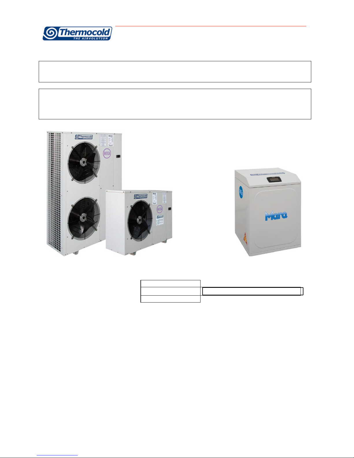
Dear customer,
Congratulation for purchasing a Thermocold product.
Thermocold operates in civil and industrial air conditioning for years to assure the best comfort with reliability, quality,
efficiency and total safety.
With this manual we try to offer you the best support from receiving, start up, use, maintenance to the most ecological
disposal.
Best regards,
Thermocold Costruzioni s.r.l.

MULTIFUNCTIONAL UNITS RLC –Installation and maintenance manual
MUMRLCHEAT_REV01_1012_UK
Pag. 3 di 31
Indice
1. Generalità ........................................................................................................................................................................4
2Receiving the unit..........................................................................................................................................................4
3Positioning....................................................................................................................................................................7
4Safety regulations .......................................................................................................................................................7
5INSTALLATION ..........................................................................................................................................................12
6Control of compressor fastening .............................................................................................................................14
7Electrical Connections...............................................................................................................................................14
8Water Connections....................................................................................................................................................15
9Perdite di carico sugli scambiatori ..........................................................................................................................24
10 Tabelle di correzione glicole etilenico .........................................................Errore. Il segnalibro non è definito.
11 Tabelle di correzione fattore di incrostazione............................................Errore. Il segnalibro non è definito.
12 Preparazione all’avviamento ................................................................................................................................26
13 Avviamento.............................................................................................................................................................28
14 Manutenzione.........................................................................................................................................................29
15 Pezzi di ricambio consigliati .................................................................................................................................30
16 Usi impropri....................................................................................................Errore. Il segnalibro non è definito.
17 Smaltimento ...................................................................................................Errore. Il segnalibro non è definito.

MULTIFUNCTIONAL UNITS RLC –Installation and maintenance manual
MUMRLCHEAT_REV01_1012_UK
Pag. 4 di 31
1. Generalità
1. OVERVIEW
1.1
Summary of guarantee regulations
A. The guarantee for Thermocold machines is 12 months from the date the machine is operated for the first time but no more than 18
months from the date of the invoice. The warranty is reduced to 6 months from the start up date for units running continuously, that is
more than 12 hours a day. The date the machine is operated for the first time means the date reported in the “1st start up form”
contained into the “machine log book”. This form should be filled in and sent, within 8 days from the start up, to Thermocold.
B. The guarantee is valid if all the installation regulations have been adhered to (both those which may have come from Thermocold and
those coming from current practice), if the “1st start up form” has been filled in and sent to the Thermocold after sales department.
C. The guarantee is subject to any faults or defects being reported within eight days from their discovery. The guarantee will only be
applied if and when the purchaser suspends use of the equipment as soon as a defect has been found.
C1. Replacement items are to be considered always ex THERMOCOLD factory. Labour costs to replace failed items either under warranty
or not, will be not of THERMOCOLD care.
D. The guarantee is valid if the first running of the machine is carried out by a Thermocold authorised assistance centre.
E. The guarantee is subject to regular maintenance of the unit which is appropriately indicated in the “machine log book” located inside
the electrical panel.
F. Warranty is automatically over in case of payments not fulfilled, non-performance of the contract and even if the units show tampering
without THERMOCOLD writing approvals.
G. Non observance of the above mentioned rules and of all the indications written on this manual, will cause the immediate loss of
warranty, getting free THERMOCOLD from any responsibility for the unit and any damages to persons or things.
2 Receiving the unit
On receiving the unit it is up to the customer to check that there is no obvious damage or pieces missing. If this is so, an immediate
complaint must be made to the carrier for damage or for not-delivery and the Receiving Card to be found inside the unit electrical panel
must be filled in. Photographic evidence must be provided for macroscopic damage. The card must be sent to Thermocold within 8 days of
receiving the goods: if it is not sent back or delayed, the complaint will not be accepted.
The unit is identified by:
Packaging label: it contains the identification data of the product.
Thecnical label: it contains the technical and performance data of the unit.
In case of loss, ask for a copy to the After Sales department.
If the identification of the product is not sure because of the damaging, removal, lack of the identification labels, the installation and
mainteinance operations become difficult.
2.1
Preliminary notions
Operate in respect of the safety regulation.
About the dimensional data of the unit and the technical data, see the chapter “Technical information”.
For loading and unloading the unit use the necessary personal protective equipment .
2.2
Delivery checks
Before the delivery:
Check the packaging and the unit have not defect caused by carriage.
Check the delivered materials correspond to the good declared in the packing list.

MULTIFUNCTIONAL UNITS RLC –Installation and maintenance manual
MUMRLCHEAT_REV01_1012_UK
Pag. 5 di 31
2.3
Unit identification
2.3.1
Label
The unit is identified by the following label.
It contains the kind of the unit (serial and size), the serial number, the production year, the electric
data, the main technical data, logo anche manufacturer address.
In case of loss request for a duplicate to the after sale service.
Tampering and/or removing the label does not allow the identification of the product, and makes
difficult any installation and maintenance operation.
2.3.2
Serial number
The serial number identifies the unit unambigously, it permit to identify the specific characteristic of
the unit and the installed components. Without this code it is not possible identifies the specific
spare parts of the unit. In case of request for repair it is necessary the model and the serial
number.
2.4
Factory inspection
Thermocold units are inspected into the factory, in appropriate areas, in accordance with internal
procedures. Each performance test carried out on the unit is possible only if the same conditions
are reproduced and maintained (charge consistency, constant temperature and evaporation - condensation and recovery capacity, quality
and tolerance of the measuring instruments etc.) in the test rooms.
The inspection conditions are those indicated by the customer in the ordering phase: if not otherwise specified, reference should be made
to the nominal performance indicated in the technical bulletin in force at the date of the Confirmation of the Order.

MULTIFUNCTIONAL UNITS RLC –Installation and maintenance manual
MUMRLCHEAT_REV01_1012_UK
Pag. 6 di 31
2.5 Handling
Verify the unit weight and the load capacity of the lifting mean. During the handling pay attention to obstacles along the route that could
damage the unit (disconnections, ramp, climb, etc.).
Verify the perfect stability during the handling operations of the unit. Do not perform dangerous operations that could damage the unit.
Make sure that the unit has the proper positioning during transportation. Placing horizontally the unit 'can
lead to irreversible damage to the compressors. Faultiness caused by uncorrect transport will not be under
warranty by the manufacturer. Immediately report an incorrect receipt. An arrow pointing straight up,
indicates the vertical positioning of the unit.
PER LA MANCATA OSSERV ANZA DELLE I STRUZIONI DI SOLLEV AMENTO SOPRAI NDICATE.
POSIZI ONATE ATTRAV ERSO I FORI INDICATI " LI FTING ".
ORIZZONTALMENTE RISPETTO AL PIANO DI APPOGGIO.

MULTIFUNCTIONAL UNITS RLC –Installation and maintenance manual
MUMRLCHEAT_REV01_1012_UK
Pag. 7 di 31
3Positioning
3.1
Installation servicing space
Respect the instructions in the dimensional drawing provided on board. Narrow installations spaces may cause:
Noise level increase
Not correct heat exchange and unit ventilation.
Maintenance difficulties or impossibility.
3.2
Condensate
The unit in order to easily discharge the condensate caused by the heat pump operation, especially during the defrosting cycle. Avoid the
condensate drain in location where people transit.
3.3
Anti-vibrantion
L’unità esterna va ancorata su antivibranti in gomma o a molla che vanno fissati nel seguente modo:
Firmly fasten the anti-vibration bottom
part to the support base plate of the unit.
Screw the fastening nut and the lock nut
to adjust the correct inclination of the unit.
The incorrect positioning of the unit can
cause damage of the compressor because
of the incorrect oil leveling.
4Safety regulations
4.1
Preamble
All Thermocold units are designed, built and inspected in compliance with the European Community Directives n° 98/37/CE (three phase
power supply), EN 60335 Part 1 and 2 , low voltage directive 73/23CEE, electromagnetic compatibility directive EMC 89/336CEE, Pressure
Equipment Directive 97/23/CEE. Before using the machine read carefully the recommendations reported in the following manual.

MULTIFUNCTIONAL UNITS RLC –Installation and maintenance manual
MUMRLCHEAT_REV01_1012_UK
Pag. 8 di 31
4.2
Definitions
4.2.1
Owner:
The legal representative of the company, body or natural person who owns the plant in which the Thermocold unit is installed: he or she is
responsible for the control and respect of all the safety regulations indicated in this manual as well as the national ones in force.
4.2.2
Installer:
The legal representative of the company appointed by the owner to position and hydraulically, electrically etc. connect the Thermocold unit
to the plant: he or she is responsible for moving and the correct installation of the unit in accordance with the indications in this manual
and with the national regulations in force.
4.2.3
Operator:
A person authorised by the owner to carry out all the operations of regulation and control on the Thermocold unit which are specifically
mentioned in this manual. He or she should keep to actions described in the manual and limit his or her action to what is explicitly allowed.
4.2.4
Technician:
A person who is directly authorised by Thermocold or, secondarily, for all EU countries except for Italy, by the distributor of the
Thermocold product, under their own responsibility, to carry out all ordinary or extraordinary maintenance operations, as well as
regulations, controls, repairs and parts replacement which may be necessary during the lifetime of the unit.
4.3
Access to dangerous areas
The access to the unit dangerous areas is usually obstructed through protection panels, which are removable, by using a tool. Axial fans
are protected with accident prevention grilles. Centrifugal fans are not protected on the discharge, as they have to be connected to ducts.
In case they have to run without ducts, it is the installer duty to provide protection grilles.
Finned coil, for units not equipped with coil protection grilles, is completely accessible with danger for cuts and abrasions. In these cases
technicians and operators must be aware about this risk.
For all the units which allow access to the cooling piping or to the packaged condensing coils with fins, without security gratings (optional)
or closing panelling, the following precautions must be taken:
-mark the areas with contact risks.
-apply warning signs.
The danger zone must be of a suitable size to avoid any contact, even accidental contact.
In the presence of safety valves without relevant remote controls, the operating area must be of a size which considers a range of action
of the discharge flow of 3 metres.
Thermocold declines any responsibility for damage to things and unauthorised personnel in case of absence of clear and static limiting
systems of the risk areas and of the relevant warning and danger signs.
4.4
General precautions
The operator must only intervene on the unit commands; he or she must not open any panels except for the one which gives access to the
command module.
The installer must only intervene on the connections between the plant and the machine; he or she must not open any machine panels nor
carry out any commands.
The following precautions should be made when approaching or working on the unit:
• do not wear jewellery, baggy clothes or any other accessory which can get caught up.
• Use appropriate protection (gloves, glasses etc.) when using an open flame (welding) or compressed air.
• If the unit is located in a closed environment, wear hearing protection.
• before disconnecting, removing tubes, filters, joints or other line parts intercept the connection tubes, empty them until the pressure
reaches that of the atmosphere.
• do not use your hands to check for possible pressure losses.
• always use tools which are in good condition; make sure the instructions have been fully understood before using them.
• make sure that any tools, electrical cables or other loose objects have been removed before closing the unit and starting it up again.
MULTIFUNCTIONAL UNITS RLC –Installation and maintenance manual
MUMRLCHEAT_REV01_1012_UK
Pag. 9 di 31
4.5
Precautions against risks due to the refrigerant
Safety data
R 410 a
Toxicity
Not important
Risks for skin touching
Splashes or sprinkles can cause chill burns. The risk of absorptions through the skin is not
relevant.
Those refrigerants could take some lightly irritating effects and in lliquid stage they have a
strong skinning effect. In this case it is necessary to rinse with fresh water the
contaminated parts of the skin
The refrigerant in liquid stage in contact with wet fabries cause freezing and adherence to
the skin. In this case it is necessary to put off the contaminated clothes to avoid freezing.
Please contact a doctor in case of irritation of the contaminated parts.
Risks for contact with the eyes
Vapors don’t take any effect. Splashes or sprinklers can cause chill burns. In those cases it
is necessary to rinse the eyes with water or with solution for ocular washings for 10
minutes. The intervention of a doctor is needed.
Risks for ingestion
Should it happen, it causes chill burns. It does not cause vomiting. The person must be
kept awake. It is needed to rinse the mouth with fresch water and to drink almosto 0,25
liters. The intervent of a doctor is needed.
Risks for inhalation
High concentration of vapours in air can lead to anaesthetic effects up to a loss of
conscience. Long exposures could give rise to cardiac arrhythmia and sometimes even to
death.
High concentrations can create a reduction of oxygen in air, with consequent possibility of
suffocation. Should it happen the person must be taken to the open air and let him to take
a rest.
Administer oxigen if needed. In case the breathing has interrupted or become irregular, it
is necessary to apply the artificial breathing. In case of cardiac arrest a heart massage
must be applied. Contact a doctor immediately.
Conditions to avoid
Use in presence of exposed flames, and of elevates levels of humidity.
Dangerous reactions
Possibility of violent reactions with the sodio, the potassio, the barium and with other
alkaline substances, incompatible materials and all the alloys containing more than 2% of
magnesium.
Protection wearing
Wear protection apparel and self respirators. Insulate the source of the loss, if this
operation can be done in safety conditions.
Behavior in case of losses or escapes
Small quantitative of refrigerant escaped at liquid state can be allowed to evaporate only if
the room is well ventilated. In case of great losses ventilate the room immediately. Plug
the loss with sand, soil or other absorbent material; avoid that the liquid refrigerant can
enter in water-drainages or losing pools.
Dismantlement
The best procedure is the recovery and the recycle. If this is not possible the refrigerant
must be conferred to an accredited system for its destruction in order to neutralize acid
and toxic by-products.

MULTIFUNCTIONAL UNITS RLC –Installation and maintenance manual
MUMRLCHEAT_REV01_1012_UK
Pag. 10 di 31
4.6
Precautions against residual risks
Prevention from risks due to the command system
• make sure the instructions for use have been understood before carrying out any work on the control panel.
• always keep the instruction manual close at hand when working on the control panel.
• start up the unit only after having certified that it is correctly connected to the plant.
• inform the technician promptly of any alarms which appear on the unit.
• do not reset the alarms to manual restart without having first identified the cause and removed it.
4.7
Prevention against residual mechanical risks
• install the unit in accordance with the provisions of the following manual.
• carry out all the maintenance operations provided for by this manual regularly.
• wear a protective helmet before entering inside the unit.
• before opening a machine panel make sure that it is firmly connected by means of a hinge.
• do not touch the air condensation batteries without having first put on protective gloves.
• do not remove the protections to the moving parts while the unit is running.
• before restarting the unit make sure that the moving part protections are in the correct position
4.8
Prevention against residual electrical risks
• connect the unit to the mains in accordance with the provisions of this manual.
• carry out all maintenance operations regularly.
• before opening the control panel disconnect the unit from the mains by means of the external knife switch.
• check that the unit has been earthen correctly before starting it up.
• control all the electrical connections, the connection cables paying particular attention to the state of isolation; replace the cables which
are clearly worn or damaged.
• carry out periodic checks of the wiring inside the panel.
• do not use cables with an inappropriate section or flying connections not even for a limited period or in an emergency.
4.9
Prevention against residual risks of a different nature
• The residual risk due to pressure are mainly coming from non functioning of the safety devices. To prevent them it is necessary to follow
the checks and replacements as following indicated (§12.1 and 13)
• To protect from safety devices exhausting it is not allowed to remove the protections while the unit is in operation and to approach the
unit without wearing the right protections. In case of accidental contact with refrigerant due to the safety valves exhaust it is necessary to
follow the above indicated (§2.5)
• carry out the plant connections to the unit by following the indications reported on the following manual and on the panels of the unit
itself.
• if a part is disassembled, make sure that it is correctly reassembled before restarting the unit.
• do not touch the discharge line of the compressor, the compressor itself or any other tube or component which is inside the machine
without putting on protective gloves.
• keep a fire extinguisher which is able to put out fires on electrical equipment near the machine.
• on units installed inside, connect the refrigerant circuit shut off valve to a network of tubes which are able to lead the possible spillage of
refrigerating fluid outside.
• eliminate any fluid loss inside or outside the unit.
• collect the discharge liquid and clean up any possible oil leakage.
• periodically clean the compressor casing of the accumulated dirt deposits.
• do not keep inflammable liquids near the unit.
• do not dispose of the refrigerant fluid and the lubricating oil in the environment.
• welding should only be carried out on empty tubes; do not approach the tubes containing refrigerant fluid with flames or other sources
of heat.
• do not bend or strike tubes containing pressurised fluids.
4.10
Precautions to be observed during maintenance operations
Authorised technicians may only carry out maintenance operations.
Before carrying out any maintenance the following must be performed:
• isolate the unit from the mains electricity by using the external knife switch.
• place a notice on the external knife switch which says “do not use - maintenance in progress”.
• make sure that any possible on-off commands are disabled.
• use appropriate safety equipment (helmet, isolating gloves, protective glasses, safety shoes etc.).
If measurements or controls must be carried out which require the machine to be running the following observations must be followed:
• operate with the electrical panel open for as short a time as is possible.
• close the electrical panel as soon as the individual measurement or control has been carried out.
• for units which are located outside, do not carry out interventions in dangerous atmospheric conditions such as rain, snow, fog etc.
The following precautions should also be taken at all times:
• never dispose of fluids contained in the refrigerant circuit into the environment.
• when replacing an EPROM or electronic card always use appropriate equipment (extractor, anti static bracelet, etc.).

MULTIFUNCTIONAL UNITS RLC –Installation and maintenance manual
MUMRLCHEAT_REV01_1012_UK
Pag. 11 di 31
• if a compressor, the evaporator, the condensation batteries or any other heavy part is to be replaced, make sure that the lifting
equipment matches the weight to be lifted.
• in the air cooled units with an independent compressor compartment, do not open the ventilator compartment without having first
isolated the machine using the knife switch on the side of the panel and only after having placed a sign which says “do not use -
maintenance in progress”.
• if modifications must be carried out to the cooling, hydraulic or electrical circuit of the unit, as well as to its command logic, contact
Thermocold.
• if particularly complicated assembly or disassembly operations are to be carried out contact Thermocold.
• always use original spare parts bought directly from Thermocold or from official dealers of the companies reported in the list of
recommended spare parts.
• if the unit is to be moved after a year of being in the site or if it has to be dismantled contact Thermocold.
MULTIFUNCTIONAL UNITS RLC –Installation and maintenance manual
MUMRLCHEAT_REV01_1012_UK
Pag. 12 di 31
5INSTALLATION
5.1
CHOISES OF THE PLACEMENT
Before the installation decide with the client the exact position where to place
the unit, paying attention to the following points:
The base must be designed to bear the unit weight;
Respect the servicing spaces between the units and other machines
or structures in order to permit the free air circulation going in and
out from the ventilators.
Verify the servicing spaces, the condensation/evaporation battery
need minimum space for a correct suction.
5.2
Positoning
Before handling the unit, verify the lifting capacity of the means respecting the
information on the packaging.
For handling the unit on orizontal base use forklift or other means in an
adeguate way paying attention on the unit weight. In case of lifting, insert bars
in the proper holes of the unit base in order to permit the positioning of the
lifting ropes and of the safety cotter pin.
In order not to damage the unit structure by the belts, use proper protections
to be put between the belts and the unit. Position the unit in the place
indicated by the client by interposing between the base and the support, a gum
mattress (thickness min. 10 mm.) or antivibration feet (optional). Fix the unit
verifying that the base is plan and without inclinations.
Verify the easy access to the idraulic and electric part. In case of installation in
places where there could be gust, fixing the unit to the support properly using
guy rope if needed.
5.3
Handling and positioning
The units have been designed to be lifted from above by means of eyebolts
and holes in the base members.
Use retractor bars to keep the lifting wires or chains away from the unit.
Lifting procedures provided with the unit have to be respected.
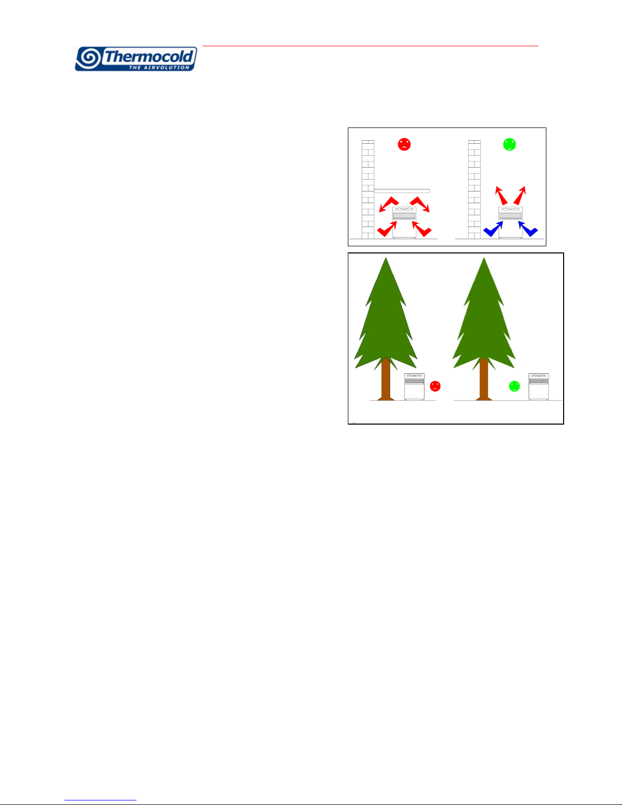
5.4
Precautions for dominant winds
Avoid obstacles on suction and discharge sides of the units. Respect the servicing spaces as shown on the units dimensional drawings.
In case of presence of dominant winds in the installation area it is strictly necessary to avoid (for units with horizontal flow fans) that such
winds blow in front of the unit (fans discharge side). In case of unit with vertical flow fans it is strictly necessary to avoid installations
where the dominant winds could cause rejected hot air to come back to the condensing coils.
If needed, install winbreak barriers (in this case contact our offices).
5.5
Precautions against direct sunshine
The direct sunshine can raise the condensation temperature and it causes the unit stopping or the missing set-up because of the high-
pressure switch intervention.
5.6
Precautions against chimney and hot air discharge
Avoid the unit installation lee side near chimney and liquid and gas discharge.
5.7
Precautions against foliage and external body
Avoid the unit installation nearby plants which could obstacle the correct air charge and discharge.
Attention
Do not use forklift trucks to lift the unit from below.
If equipment for lifting from above is not available, using rollers may move the unit.
The surface on which the unit is placed must be flat and strong enough to withstand the weight of the unit while running.
In order to reduce the transmission of vibrations to the supporting structures, fit shock absorbers in every fastening point. Rubber shock
absorbers are recommended for units installed on the ground, spring shock absorbers for units installed on roofs. Open spaces around the
unit must be provided for in order to allow for the passage of necessary airflow and in order to allow normal maintenance to be carried out
(as shown on general catalogues).
ATTENTION: in case two units have to be installed side by side, the distance of respect must be doubled.
NO
YES
YES
NO
MULTIFUNCTIONAL UNITS RLC –Installation and maintenance manual
MUMRLCHEAT_REV01_1012_UK
Pag. 13 di 31
After the unit has reached the final position, fix the antivibration bolts.
5.8
Precaution against frost risk of the idraulic pipes
It is necessary to insulate pipes in the plant to avoid extreme heat loss and to protect them from weather conditions. The problem of
wather pipes freezing could appear in two different situations:
Unit standby, with mode on, but electrically connected: in this case, the unit has frost resistances, which protect the wather
locally contained in the exchangers and in the pipes from ice formation. These resistances do not guarantee the protection
against the frost in the outdoor connection pipes, to be prevent by frost protection systems. Thermocold suggest to insert frost
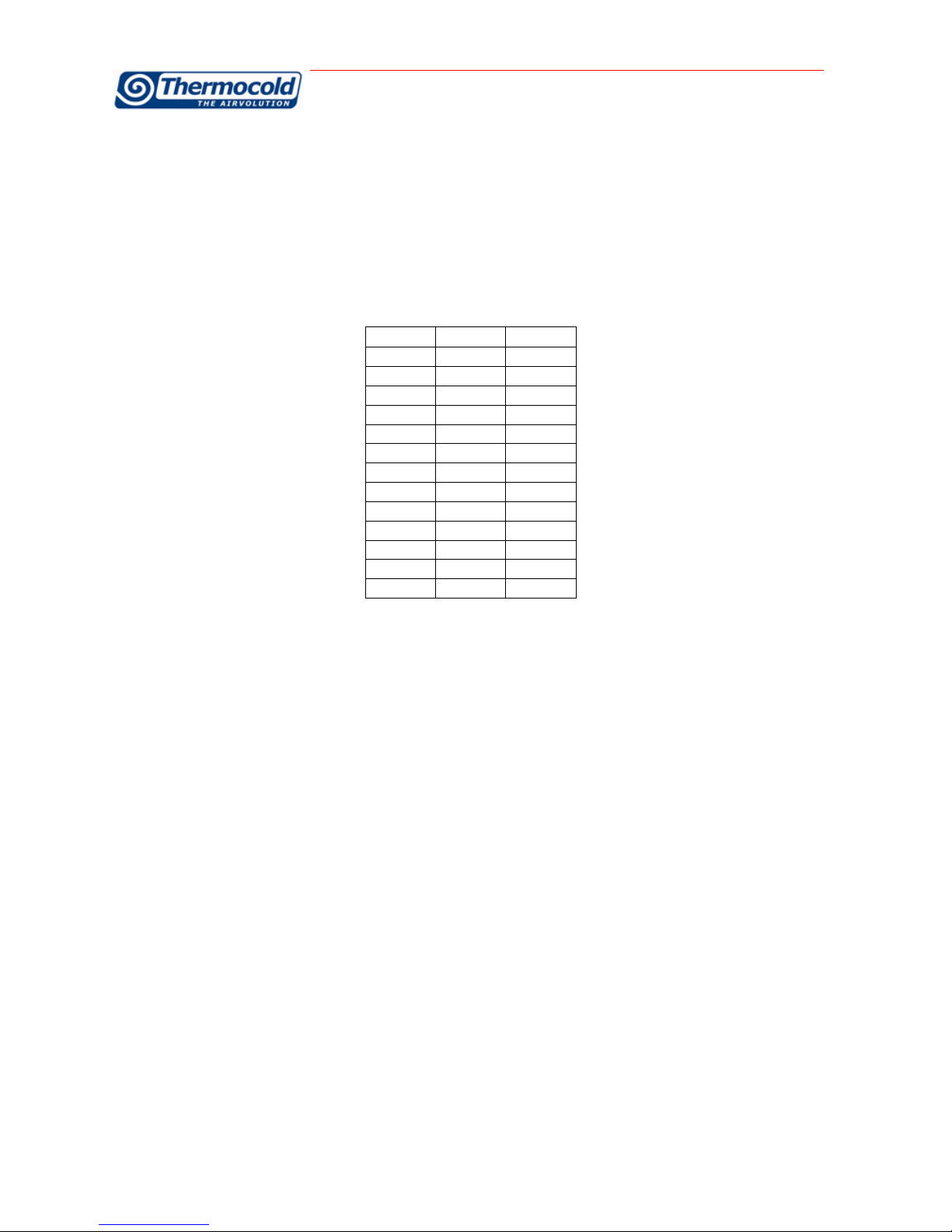
thermostatic resistances on every outdoor pipes. In the following table there are the indicative electric power per pipe linear
meter.
nd
inch
W/mt
8
1/4"
5
10
3/8"
5
15
1/2"
5
20
3/4"
10
25
1"
13
40
1" 1/2
30
50
2"
50
65
2" 1/2
80
80
3"
120
100
4"
200
125
5"
300
150
6"
450
200
8"
750
Electrically unconnected unit: in this case the frost resistances of the unit could not guarantee the protection. So it is absolutely
necessary unload the unit content for A.C.S., instead for air conditioning it is necessary to add the correct glycol quantity
indicated in the chapter: “Ethylenic glycol correction table”.
5.9
Precaution for very low outdoor temperature
The unit has variable flow pumps on the primary circuit which allow to start with low water temperature in the storages or in the plant,
automatically, but the water temperature should not be lower than 10°C.
In case of installation conditions with a lower temperature:
1. If there are storages, insert electric resistances to be calculated by:
PrWatt = V x (10 –tmin) / 860
where: PrWatt is the resistance power (Watt) and tmin is the lower temperature (°C)
2. If there are not storages, mantain the temperature higher than 10°C the water temperature by inserting termstatic resistance
with power calculated as in case 1.
MULTIFUNCTIONAL UNITS RLC –Installation and maintenance manual
MUMRLCHEAT_REV01_1012_UK
Pag. 14 di 31
6Control of compressor fastening
The compressors are fitted on shock absorbers. After receiving the unit check if there are blockages to fasten the compressors during the
transportation. If there are, it is necessary to remove blockages put to fasten the compressors feets before the start-up otherwise the
warranty is not valid.
7Electrical Connections
7.1
Electrical power supply
The mains power supply characteristics have to match the unit’s absorption. The mains power supply tension must correspond to the
nominal value ± 10%, with a maximum difference between the phases of 3%.
7.2
Power connections
Protect the unit electric box power supply circuit with protection devices (not included in the supplied equipment)
Connect the line terminals with a three-core cable of a section, which is appropriate to the machine absorption.
The switch and the fuses like all the power connections must comply with the regulations in force.
7.3
Unbalance between the supply tension phases
Do not run the electrical motors when the voltage unbalance between the phases is more than 3%.
Use the following formula to check:
100*
averagevoltage averagefromdeviationeMaxvoltag
entunbalancemVoltage%
Important
If the mains voltage has an unbalance of above 3%, contact the company, which distributes the electrical energy. If the unit functions with
a unit voltage unbalance between the phases of above 3% the guarantee is invalid.
Maximum allowable tolerance ot unbalance between the phases 2%
Maximum allowable tolerance on power supply 5%
The electrical data refer to the standard units, depending on the accessories or versions required data may vary.
Check that the electrical equipment of the machine are compatible with the information in the technical bulletins or with the data on the
nameplate of the unit '.

MULTIFUNCTIONAL UNITS RLC –Installation and maintenance manual
MUMRLCHEAT_REV01_1012_UK
Pag. 15 di 31
8Water Connections
8.1
Preamble
The connection tubes have to be supported adequately in order that their weight does not damage the plant.
The above-mentioned installation indications represent necessary conditions for the guarantee to be valid.
Thermocold is at your disposal to examine any different requirements, which have to be approved before starting up the chiller.
It is necessary that the water flow rate to the unit is compatible with the evaporator one. It is also necessary that the water flow rate is
kept uniform while the unit is running.
8.1.1
Calculation of minimum water content and flow rates
To operate properly, the unit needs a water content sufficient to avoid constant changes of the cycle or too frequent on-of of the
compressors. See the chapter on the thecnical data. The declared content can be reduced by the amount contained in the distribution
piping system only for the air conditioning system. Undersized tanks reduce the progect useful life of the unit.
8.2
Equipment for the water circuit regulation
Centrifugal motor pump block or packaged circulator.
Assures the discharge and the prevalence necessary to supply shell&tubes or plate heat exchanger, the tank and the utility.
Automatic filling unit
Assures the water pressure in the plant is maintained at least 1.5 bar, automatically resetting it when necessary.
Safety valve
Takes care of opening the plant in atmosphere if the pressure exceeds the value of 6 bar.
Expansion tank
Takes care of compensating small water hammering and variations of volume for different temperatures.
Check valves
Take care of intercepting the pump for possible maintenance.
Check valves
Take care of guarantee the waterflow direction and to avoid the heat propagation downstream of the plant when the correspondent pump
is switched off.

MULTIFUNCTIONAL UNITS RLC –Installation and maintenance manual
MUMRLCHEAT_REV01_1012_UK
Pag. 16 di 31
8.3
Hydraulic scheme for units connection
8.3.1
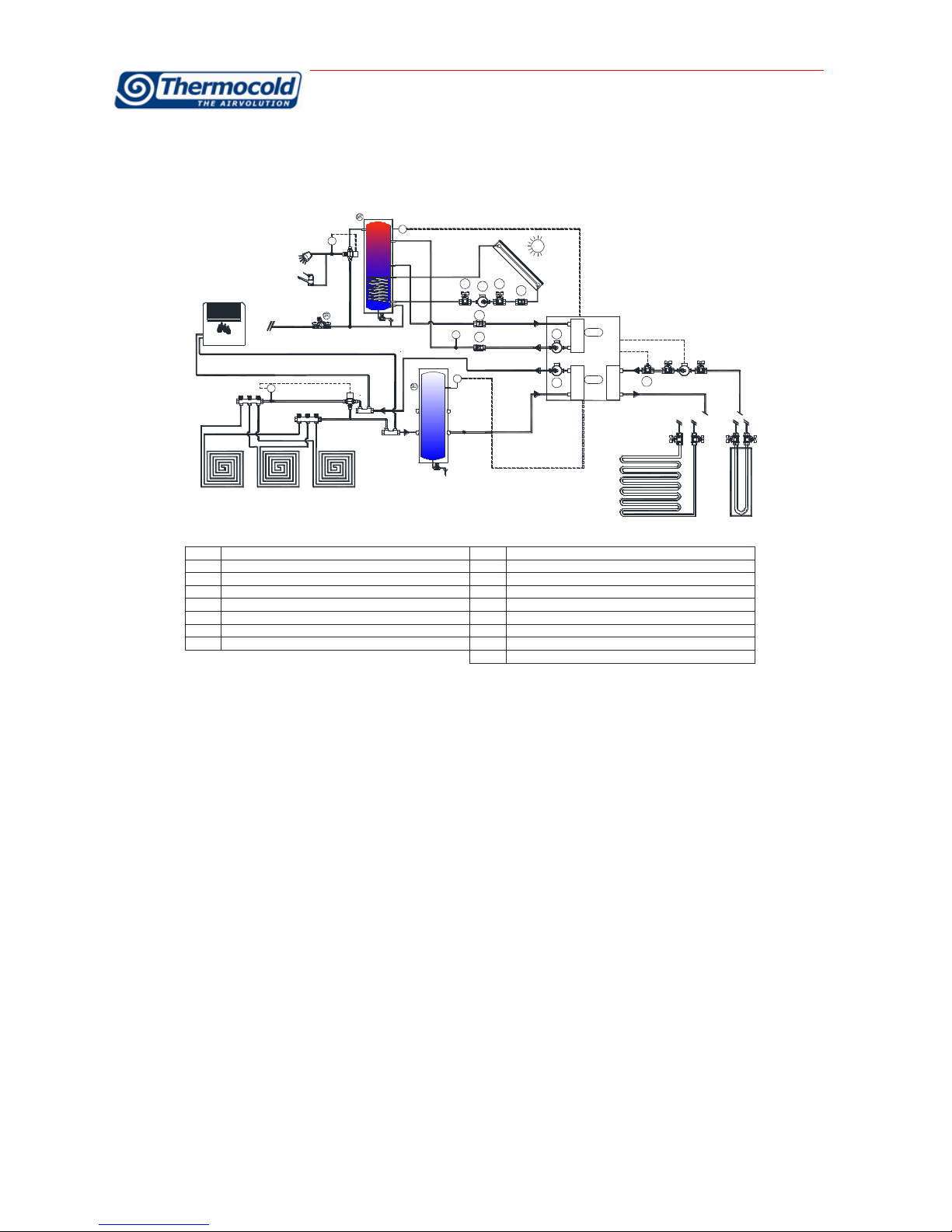
Air- Water unit connection scheme
T
M
PU
PR
REC
EWR
DEHUMIDIFIER
DEUMUDIFICATORE DEHUMIDIFIER
DEUMUDIFICATORE DEHUMIDIFIER
DEUMUDIFICATORE
T1
SFSV
Check the sanitary water tank and the correct installation.
If you want to turn off the hot sanitary water pump (PR), when there is no demand, insert the T1 temperature probe inside the storage
tank placed at the entrance of the hot sanitary water heat exchanger. The hot sanitary water pump is driven by the Controller of the units
according to the hot sanitary water demand. For instructions for the above mentioned feature please refer to the wiring diagrams supplied
with the unit.
To ensure an optimum operation of the unit, especially if the units starts with low inlet water temperature during hot sanitary water
operating mode, it may work outside or near the allowed limits (see data sheets), it is necessary using variable flow rate water pumps
both to avoid low pressure starts up and also to ensure the plant reaches the required temperature settings.
As regards the connection to the plant, we recommend the use of a water tank in order to minimize the cycle inversion and frequent
compressors start and stops, however, the units works even in without water tanks since the thermoregulation is handled with variable
flow pumps that are activated so as to reduce the plant inertia. In this way it is always possible to automatically follow the effective plant
demand.
Place the outlet water probes to 1 mt minimum distance from the check valves located downstream of the exchanger.
Before a machine stop with temperatures close to 0 ° C, provide to evacuate the contents of the exchanger with compressed air in order
to avoid breakage caused by ice formation.
It is possible to connect the MULTIFUNCTIONAL units through tanks equipped with coil or double coil to an additional heat source or
already existing ones. It is necessary to connect the additional heat sources to the coil of the tank and check the real capacity according
to the additional heat souce capacity.
In case of integration with solar panels systems, when there is no heating demand during summer, it may occur to reach water
temperatures out of the operating limits of the unit, it is required to install check valves upstream and downstream of the heat
exchangers, in order to avoid alarms on the unit for excessive water temperature or the safety valves intervention causing also a not
proper calibration of the refrigerant charge.
In case of direct connection between the hot sanitary water heat exchanger and the users, it is necessary to plan cleaning cycles. The
cleaning frequency must be established according to the water hardness.
PU
POMPA UTENZE - CLIMATIZATION PUMP
SF
VALVOLE DI SFIATO - VENT VALVE
PR
POMPA RECUPERO - RECOVERY PUMP
SV
VALVOLA DI SICUREZZA - SAFETY VALVE
F
RACCOGLITORE IMPURITA’ - STEEL MESH STRAINER
ET
VASO DI ESPANSIONE - EXPANSION VESSEL
1
AI SANITARI - TO SANITARY
GR
GRUPPO DI RIEMPIMENTO - FILLING GROUP
2
DALL’ACQUEDOTTO -FROM PUBLIC WATER SUPPLIER
WTS
SERBATOIO UTENZA SANITARI - WATER TANK SANITARY
3
DAI SANITARI - FROM SANITARY
WTC
SERBATOIO DI UTENZA - WATER TANK CLIMATIZATION
MULTIFUNCTIONAL UNITS RLC –Installation and maintenance manual
MUMRLCHEAT_REV01_1012_UK
Pag. 17 di 31
8.3.2
Water-water unit connection scheme (geothermal applications)
T
T
T
VR
VR
RBRB
VR
P3
P1
P1
ET VASO DI ESPANSIONE - EXPANSION VESSEL
- CLIMATIZATION WATER TANKSERBATOIO UTENZE CLIMATIZZAZIONESU
SR SERBATOIO UTENZE ACS - SANITARY WATER TANK
- RECOVERYRECUPEROREC
EWR EVAPORATORE/CONDENSATORE -EVAPORATOR / CONDENSER
- TEMPERATURE PROBESONDA DI TEMPERATURAT
M VALVOLA MISCELATRICE A 3 VIE - 3 WAY MIXING VALVE
- SHUTT OFF VALVEVALVOLA DI INTERCETTAZIONER
SF VALVOLA DI SFIATO - VENT VALVE
F RACCOGLITORE IMPURITA' - STEEL MESH STRAINER
- FILLING GROUPGRUPPO DI RIEMPIMENTOGR
SC SCARICO
P2 POMPA SECONDARIO - SECONDARY PUMP
- PRIMARY PUMPPOMPA PRIMARIOP1
- SAFETY VALVEVALVOLA DI SICUREZZASV
- DRAINAGE
P3 POMPA SOLARE TERMICO - SOLAR THERMAL PUMP
T
M
DEHUMIDIFIER
DEUMUDIFICATORE
M
TEWR
REC
PRS
PRS VALVOLA PRESSOSTATICA - PRESSURE REGULATOR
For units with geothermal source, a system for regulating the condensation or evaporation pressure must always be mounted. The best
regulation system is a variable flow system checking the condensation pressure during summer mode and the evaporation pressure
during winter mode. The controller has a 0-10 V signal configured for this function.
Another solution is the use of a pressure control valve operating in chiller mode and a two-way valve that allows to work with full flow in
heat pump mode.
The geothermal source pump must be controlled by the unit and it is turned off when it is not required its activation as for example
during cooling + recovery operation mode. During other operationg modes the groundwater pump is off and will start again before the
activation of the compressor. To avoid flow switch alarms due to late flow reading it is recommended to install the flow switch
immediately downstream of the pump.
MULTIFUNCTIONAL UNITS RLC –Installation and maintenance manual
MUMRLCHEAT_REV01_1012_UK
Pag. 18 di 31
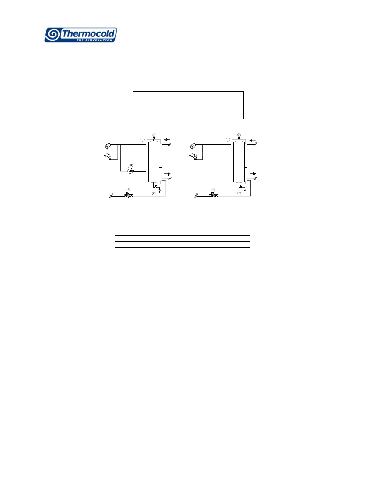
8.3.3
Connection scheme of the HSW tank with hot ring or with water to waste
In the case of the preparation of the ring hot, it is possible to order the tank, with the only preparation on the secondary. In this case the
circulator of such a ring is on customer charge. Otherwise you can select the pump from the Thermocold tank catalogue.
T T
- TEMPERATURE PROBESONDA DI TEMPERATURAT
SF VALVOLA DI SFIATO - VENT VALVE
- FILLING GROUPGRUPPO DI RIEMPIMENTOGR
SC SCARICO - DRAINAGE
PR POMPA RETE DI RICIRCOLO - RECIRCULATION PUMP
CONNESSIONI IDRICHE SERBATOIO ACS
SENZA RETE DI RICIRCOLOCON RETE DI RICIRCOLO
HSW TANK
CONNECTION
WITHOUT RECIRCULATING SYSTEM
WITH RECIRCULATING SYSTEM
MULTIFUNCTIONAL UNITS RLC –Installation and maintenance manual
MUMRLCHEAT_REV01_1012_UK
Pag. 19 di 31
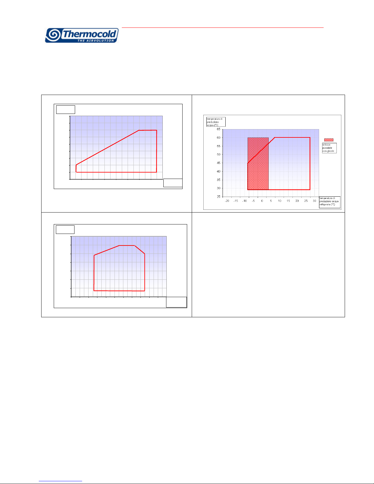
9Operating limits
Air to water units
Mara
Winter space heating and hsw production operating mode:
25
30
35
40
45
50
55
60
65
70
-20 -15 -10 -5 0 5 10 15
temperatura aria
esterna (°C)
temperatura di
produzione
acqua (°C)
Summer air conditioning and simultaneuosly hsw production operating
mode
Summer air conditioning operating mode:
15
20
25
30
35
40
45
50
-20 -15 -10 -5 0 5 10 15 20
temperatura di
produzione acqua
refrigerata (°C)
temperatura aria
esterna (°C)
Notes: working outside of the allowed limits compromises the unit
operation. In these conditions, the unit will suffer serious permanent
damage not under warranty.

MULTIFUNCTIONAL UNITS RLC –Installation and maintenance manual
MUMRLCHEAT_REV01_1012_UK
Pag. 20 di 31
Mara Exr
Winter space heating and hsw production operating mode:
Summer air conditioning and simultaneuosly hsw production
operating mode:
Summer air conditioning operating mode:
Notes: working outside of the allowed limits compromises the unit
operation. In these conditions, the unit will suffer serious
permanent damage not under warranty.
Table of contents
Popular Air Conditioner manuals by other brands

Fujitsu
Fujitsu ASYG 09 LLCA installation manual

Toshiba
Toshiba RAS-18SKV-E Series Service manual

Argo
Argo SWAN EVO operating instructions

Daikin
Daikin FTXS50EV1B installation manual

Mitsubishi Electric
Mitsubishi Electric MSC-GE20VB operating instructions

Challenge
Challenge MPPHA-05CRN1-QB6 instruction manual


