Thermoscreens PHV2000NT Guide

T9901018-1 Page 1 of 26
PHV2000NT CHILLED WATER HEAT PUMP,
SENSIBLE/DRY COOLING UNIT
INSTALLATION, OPERATION & MAINTENANCE INSTRUCTIONS
For use with PUHZ-HW140VHA2 or YHA2 Outdoor Units
PLEASE READ THESE INSTRUCTIONS CAREFULLY BEFORE ATTEMPTING INSTALLATION
Thermoscreens Ltd
St. Mary’s Road Nuneaton
Warwickshire England
CV11 5AU
Email: [email protected]
Tel: +44 (0) 24 7638 4646
Fax: +44 (0) 24 7638 8578
www.thermoscreens.com
English

T9901018-1 Page 2 of 26
Thermoscreens / Mitsubishi Electric
PHV2000NT Chilled Water Heat Pump,
Dry Cooling Unit - Split System
The PHV2000NT Chilled Water Heat Pump System consists of :-
a Thermoscreens 'PHV2000NT Dry Cooling Unit' with Mitsubishi Electric PAC-IF010B-
E Interface PCB and PAR-W21MAA Controller and Siemens RDG400 Manual Room
Control for manual control by the end user *
a Mitsubishi Electric PUHZ-HW140VHA2/YHA2 Air to Water Outdoor Unit *
*- supplied by Mitsubishi Electric
Water Pipework Installation and Water Pump(s) ‡
Electrical installation
‡
a 2-pole On/Off Switch for the end user ‡
a 2-pole Isolator for the S1, S2, S3 link ‡
‡- installation items supplied and fitted by installer
Thermoscreens PHV2000NT
Dry Cooling Unit
Mitsubishi Electric
PUHZ-HW140
Outdoor Unit
Permanent 1-phase mains electrical supply
Siemens RDG400
Manual Room Control
On/Off – Input
Cooling Temp Set Point – Input
Air Temp Sensor – Input
(alternative to return air temp sensor in unit)
S1, S2, S3 link
Permanent electrical supply
(from local switched isolator)
Pump
Flow and Return water pipework
Remote Signals
On/Off - Input
Mitsubishi Error - Output
Room over-temp alarm - Output
Chilled water pipework
Electrical cables Control cables
Supplied and fitted inside plastic end
cap. Not used for control by the end
user, only needed so the outdoor
unit will run.
2-pole On/Off Switch for End User
(easily accessible next to unit)
[connect fire alarm circuit here]
Mitsubishi Electric
PAR-W21MAA
S1, S2
Isolator
T9901018-1 Page 3 of 26
DESIGN INFORMATION
The Thermoscreens dry cooling unit is designed to provide up to 12kW * of dry/sensible
cooling (SHR/SHF = 1) (e.g. zero latent cooling with no condensate coming from the unit)
to areas where cooling is required but with no increase in moisture content of the air, i.e. IT
Server Rooms, laboratory areas, etc. It will do this if the room environmental conditions are
no higher than 24°C dry bulb with a relative humidity no greater than 40% and the chilled
water flow temperature entering the unit is no lower than 10°C **. The 10°C chilled water
flow temperature is set at commissioning and controlled by the Mitsubishi Electric PUHZ-
HW140 Outdoor Unit. Under design conditions the return water temperature from the dry
cooling unit is 13°C with a flow water temperature of 10°C.
* - output may be reduced if antifreeze additives are used.
** - validated by tests carried out at independent test house BSRIA, UK.
Chilled water pipework and water pump(s) must be supplied and installed to supply the
chilled water from the PUHZ-HW140 Outdoor Unit to the Thermoscreens dry cooling unit.
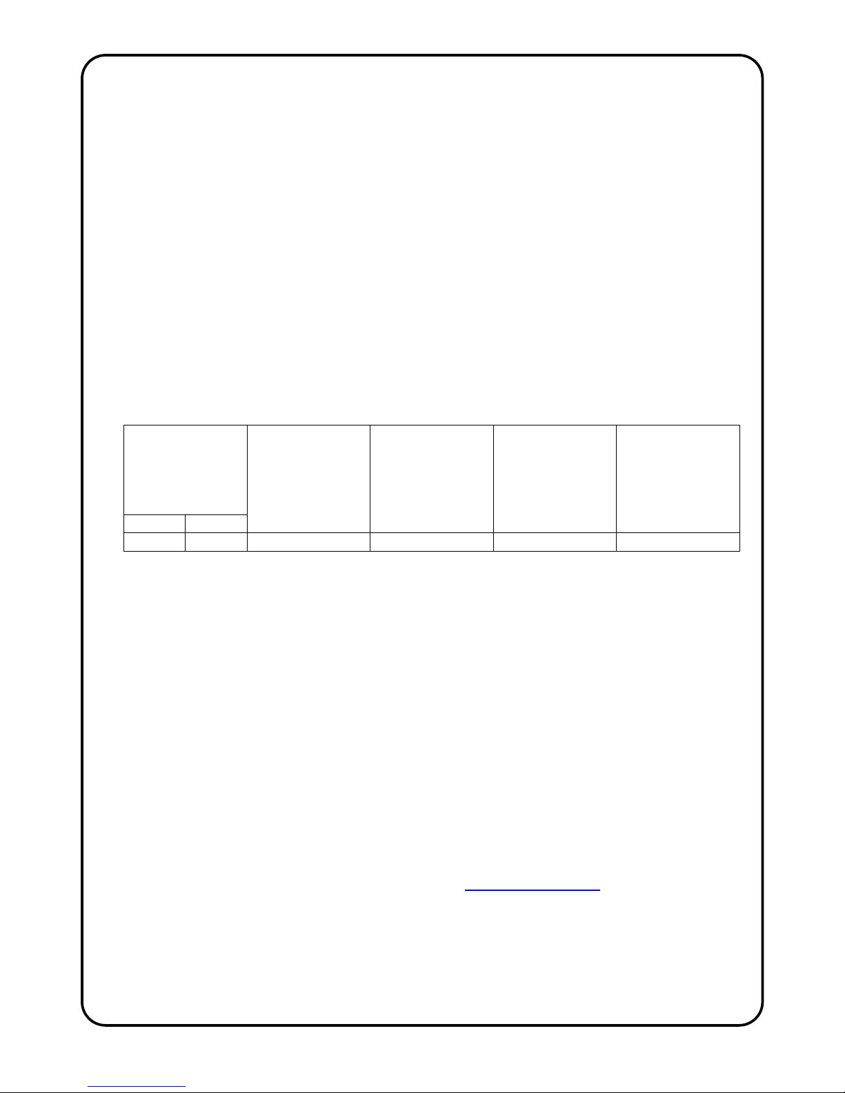
Hydraulic details for this installation are as follows:
Table 1
Water Volume
Flow Rate for
12kW maximum
output
Hydraulic
Resistance of
water coil in
Thermoscreens
Dry Cooling Unit at
3.2 m3/h
(kPa)
Hydraulic
Resistance of heat
exchanger in
Mitsubishi PUHZ
Outdoor Unit at
3.2 m3/h
(kPa)
Water Volume of
water coil in
Thermoscreens
Dry Cooling Unit
(litre)
Water Volume of
heat exchanger in
Mitsubishi PUHZ
Outdoor Unit
(litre)
m
3
/h l/min
3.2 53 36 15 5.1 2.5
A separate, self contained ‘closed/unvented’ water system must be used for the flow and
return water pipework between the Thermoscreens dry cooling unit and the Mitsubishi
Electric outdoor unit. This should incorporate water pump(s), expansion vessel, pressure
relief valve, filling loop, pressure gauge, automatic air vents, water dirt trap device, flow
setter valve (recommended), drain valve(s), isolating valves and union fittings for the
removal of components. The water system must be suitable for chilled water and installed
and commissioned by a qualified technician in accordance with CIBSE Commissioning
Code W, CIBSE KS9, BSRIA AG 2/89.3 and BSRIA AG 1.2001.1. For the Mitsubishi
Electric system to operate correctly the minimum water volume of the water system must
be 80 litres, so a buffer vessel may be necessary. A water dirt trap device should be
incorporated into the chilled water system to help protect the system from any
contamination and provide an ongoing indication of the system water condition. Please
note that the Fernox Boiler Buddy water dirt trap device has a hydraulic pressure drop of
12kPa (clean) at a water flow rate of 3.2m3/h**. If pressure drop in the system becomes an
issue it may be necessary to use a commercial type water strainer with a lower hydraulic
pressure drop. It is recommended that a flow setter valve is fitted in the water pipework
system to verify the water flow rate. We recommend the AV23 SETTER Bypass SD 20-70
l/min DN32 (Code No.223.2561.00) by Taconova www.taconova.com or equivalent.
For a self contained, close coupled 35mm pipework installation the following suggested
water pumps are given as a guide only :-
Wilo TOP-S 30/10 (230V/1ph/50Hz) or Grundfos UPS32-120F (230V/1ph/50Hz)
Pump selection must of course be checked by a Building Services Engineer for
each installation !
T9901018-1 Page 4 of 26
Because of the relatively high hydraulic pressure drops it may be cost effective to
incorporate two water pumps operating in series. Pump(s) need to be 230V/1ph/50Hz with
a total maximum current = 2A for all pumps combined. If the pump(s) total current is higher
than this an interface relay/contactor will need to be used.
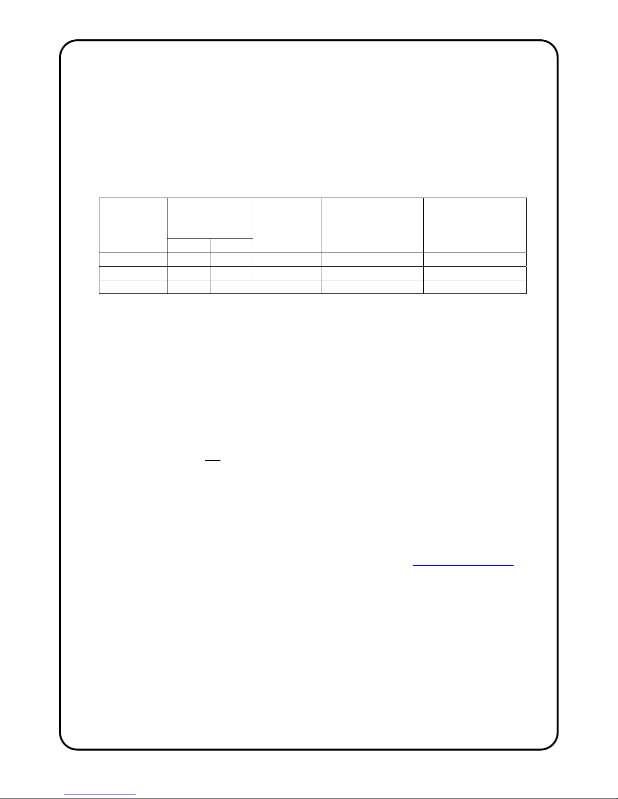
If so required, the cooling duty can be reduced from 12kW and a smaller water pump
used. Dry cooling will still be achieved providing the room environmental conditions are no
higher than 24°C dry bulb with a relative humidity no greater than 40% and the chilled
water flow temperature entering the unit is no lower than 10°C. The following table gives
details for this: Table 2
Cooling Duty
(kW)
Water Volume
Flow Rate
Water Return
Temperature
(°C)
Hydraulic Resistance
of water coil in
Thermoscreens Dry
Cooling Unit
(kPa)
Hydraulic Resistance
of heat exchanger in
Mitsubishi PUHZ
Outdoor Unit
(kPa)
m
3
/h l/min
11.5 2.6 44 13.8 24 10
11.0 2.0 33 14.8 14 6
10.5 1.6 26 15.7 9 4
Calculated for Water Flow Temperature = 10°C
In case of emergency, condensate could form on the cooling coil if there was a failure in
the air conditioning on site or environmental conditions in the server room went above
24°C/40%Rh due to some other circumstance, e.g. doors left open, extreme weather
conditions. To allow for this the Thermoscreens dry cooling unit is supplied with an integral
condensate drain tray and outlet pipe to drain condensate away from the unit. A gravity
condensate drain system extending to a suitable drain outside of the room must be
supplied and fitted by the installer in case this emergency situation were to occur. This
should be connected to the 15mm copper drain pipe that protrudes from the right-hand
rear of the cooling unit behind the plastic end cap. Condensate pumps are not
recommended but if a gravity drain system is impossible and a condensate pump is the
only alternative it must not be fitted at the dry cooling unit because of reliability issues with
these devices. If the condensate needs to be pumped to a higher level with a condensate
pump this should be done in a separate room away from the server room. If there was a
spillage of condensate at the pump, therefore, it will not occur in the server room. Suitable
condensate pumps are Peristaltic or Rotary Diaphragm type with a suction head. The
condensate pump needs to have the facility so it only operates if water is detected in the
drain tray. It should also have a pump overrun to empty the drain tray as much as
possible. We recommend the Blue Diamond rotary diaphragm type with cooling signal
sensor (drainStik) manufactured by Charles Austen Pumps Ltd. (www.miniblue.co.uk).
The condensate drain tray inside of the Thermoscreens dry cooling unit has a metal fixing
bracket located at the right hand end so a condensate sensor can be fixed in the tray in
the appropriate position by the installer. There is a rubber grommet with 9.5mm hole fitted
in the fixing bracket which will accept a 10mm diameter condensate sensor. Different size
grommets can be fitted by the installer to suit other condensate sensors or if the grommet
is removed a larger condensate sensor can be located in the 13mm diameter hole in the
fixing bracket and held with silicon sealant. See also the manufacturer’s instructions that
come with the condensate pump for further information.
Valuable or delicate equipment should not be placed beneath the dry cooling unit or
directly in the path of the cool air discharge from the unit.
T9901018-1 Page 5 of 26
The Thermoscreens dry cooling unit operates from its own separate 1 phase electrical
supply (1L+N+E) with a local switched isolator, see Page 12, and the fan within the unit
runs continuously when this electrical supply is connected. If the local switched isolator is
not easily accessible by the end user there should be a 2-pole On/Off switch fitted in an
easily accessible position next to the dry cooling unit. The Mitsubishi Electric interface pcb
fitted inside the dry cooling unit, however, is powered via the S1, S2, S3 wiring from the
outdoor unit and a 2-pole S1, S2 isolator is required for this electrical/communications link.
Room temperature control of the Thermoscreens dry cooling unit is done using a Siemens
RDG400 Manual Room Control that is supplied with the unit. This room control is used to
select the target temperature (set point) of the room air temperature and it then switches
the Mitsubishi Electric cooling system On and Off to achieve this temperature. The room
air temperature is measured using either a return air temperature sensor in the air intake
of the dry cooling unit or via an integral air temperature sensor within the RDG400 manual
room control. This is selectable at the time of commissioning. A volt free remote On/Off
control switch or BMS Dig/Output signal can be connected to the Thermoscreens dry
cooling unit to turn the cooling system On and Off as an alternative to manually switching it
On and Off at the RDG400 manual room control via the target temperature.
A separate thermostat with its air sensor positioned in the air intake is incorporated within
the Thermoscreens dry cooling unit. This is to provide warning of elevated room air
temperatures which could indicate a fault in the air conditioning system or some other
problem. This thermostat can be set during commissioning to between 15°C and 35°C and
terminals are provided within the unit for external monitoring of the contacts opening or
closing on rising temperature. Contacts are rated 16A(4A) at 230v AC.
The Thermoscreens dry cooling unit includes the facility to provide a global error signal
should an error occur in the Mitsubishi Electric heat pump system.
A Mitsubishi Electric PAR-W21MAA Remote Controller is supplied and pre-fitted inside the
left hand end cap of the Thermoscreens dry cooling unit. It is needed for the Mitsubishi
Electric heat pump system to operate and is also useful to diagnose error messages. It is
not used for control of the system by the end user, this is done via the Siemens RDG400
manual room control, see above.
The Thermoscreens dry cooling unit is designed only for use with a Mitsubishi Electric air
to water heat pump system for use on R410A. The complete Thermoscreens/Mitsubishi
Electric air to water heat pump system, including fridge pipework, water pipework system,
wiring, controls, etc. must be installed only by an approved Mitsubishi Electric refrigeration
contractor in accordance with the relevant installation instructions.
Persons using the dry cooling system must be given adequate instruction and supervision
concerning the use of the appliance by a person responsible for their safety. The cooling
system is not intended for use by persons (including children) with reduced physical,
sensory or mental capabilities.
These instructions must be read in conjunction with the separate Mitsubishi Electric
instructions that come with the PUHZ-HW140 Outdoor Unit. All instructions should be kept
by the building facilities manager for future reference.

T9901018-1 Page 6 of 26
UNPACKING THE DRY COOLING UNIT
The following items are supplied and packaged within the dry cooling unit box :-
There will also be a PUHZ-HW140VHA2 or YHA2 Air to Water Outdoor Unit supplied by
Mitsubishi Electric.
The complete Thermoscreens/Mitsubishi Electric dry cooling system, to provide dry cooling to
a server room or other space, including chilled water pipework system and wiring is to be
installed only by an approved Mitsubishi Electric contractor.
For your records
Date of Purchase……………………………..
Supplier/Installer………………………..…….
Serial Number…………………………………
For warranty purposes proof of purchase is necessary so please keep a copy of your invoice.
IMPORTANT
This Dry Cooling Unit is intended only for use with a Mitsubishi Electric
PUHZ-HW140VHA2 or YHA2 Air to Water Outdoor Unit.
These instructions must be read in conjunction with the separate instructions that
come with the Mitsubishi Electric PUHZ-HW140VHA2 or YHA2 Air to Water Outdoor
Unit.
(All documentation supplied with the unit should be stored and kept for future reference.)
If anything is missing or
damaged please contact
your supplier immediately.
PHV2000NT Dry Cooling Unit
End caps are supplied loose to
be fitted during installation
Mitsubishi Electric PAR-W21MAA
fitted inside LH end cap
Siemens RDG400
M
a
n
ua
l R
oo
m
Co
n
t
r
o
l
Wall Brackets and Fixin
g
Bolts
for if Dry Cooling Unit is to be fixed to a wall

T9901018-1 Page 7 of 26
150mm
minimum clearance
COOL AIR
White unit shown for picture clarity only
INSTALLING THE DRY COOLING UNIT
The dry cooling unit has been designed to be mounted on a wall or suspended from
above using M10 drop rods. It must not be installed on the outside of the building,
or built into a cabinet or recessed in anyway.
Location
The dry cooling unit must be mounted so the unit is
horizontal and level and the discharge grille faces
downwards. The discharge grille must be at least
2.4m above ground level and located so the
downwards flowing cool air will distribute throughout
the room or across equipment to be cooled. It
should not, however, be positioned directly above
valuable or delicate equipment in case of water
leaks or an emergency condensate situation, e.g.
doors left open, extreme weather conditions.
Beware of obstructions in the room that may
interfere with air distribution. Leave a gap of 150mm
minimum above the unit to allow for installing the water pipework.
Wall Fixing
There are three wall brackets supplied and these need to
be bolted to the rear face of the cooling unit as shown in
the adjacent picture using the M10 bolts supplied. A
suitable wall fixing system (not supplied) needs to be
used to fix the brackets to the wall, taking into account the
type of wall and the weight of the unit - 76kg.*
Step 1. Refer to Figure 1, Page 8 for mounting details
and drill the fixing points in the wall.
Step 2. Screw in the top wall bolts leaving a small gap
between the bolt head and the wall. Lower the cooling
unit onto the bolts via the key-hole slots in the top of the
wall brackets and then screw in the bottom wall bolts.
Step 3. Ensure all fixing bolts are tightened and the dry
cooling unit is safely secured to the wall.
Ceiling Suspension
There are six M10 threaded inserts provided in the top
face of the cooling unit (see Figure 1, Page 8 for
positions) so it can be suspended on M10 threaded
hanging rods with lock nuts (not provided). All six
suspension points must be used. Ensure each of the
hanging rods is secured onto a suitable structure that can
support the weight of the unit - 76kg.* Screw the M10
hanging rods into the threaded inserts by a minimum of
20mm and fit locking nuts to prevent the rod rotating and
coming away from the casing. Do not screw the hanging
rods too far in or they could interfere with internal
components.
*It is the sole responsibility of the installer to ensure that
the building fixing locations and suspension system used
are suitable for the dry cooling unit being installed.
White unit shown for picture clarity only
T9901018-1 Page 8 of 26
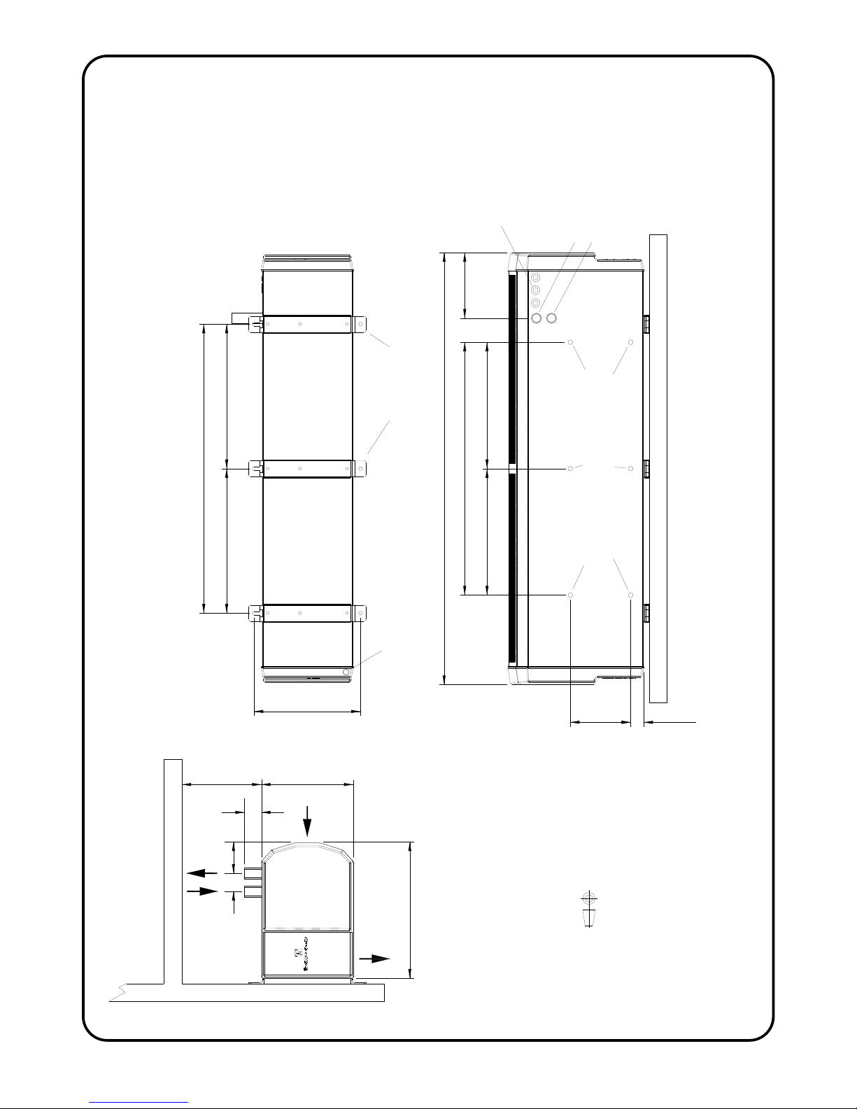
295
912
1824
798
1596
2296
168 36
255
377
Water Return Connection
60
Electrical Supply and
Control Wiring Inlets
for pipes
c. 150 min.
6 x M10 threaded holes for M10 drop rods
IMPORTANT - Use all 6 drop rod holes
3 Holes x 20mm
Water Connections, Rp1
56 70
(1in. BSP Internal.)
Emergency Condensate Connection
at rear of plastic end cap, 15mm copper
798
215
912
AIR
AIR
Wall Mounting Brackets
FLOW RETURN
Water Flow Connection
FIGURE 1 – DIMENSIONS OF THERMOSCREENS DRY COOLING UNIT
T9901018-1 Page 9 of 26
FLOW RETURN
access
p
anel
screw
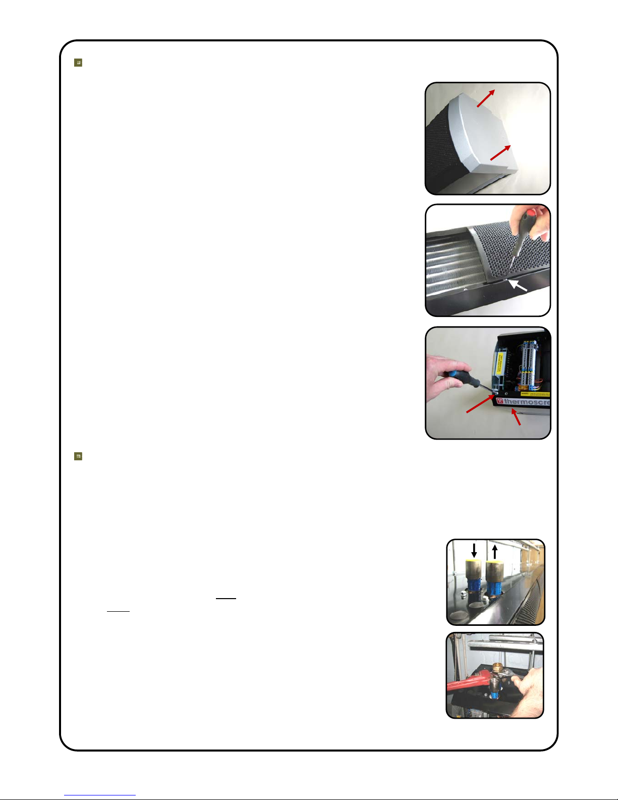
To gain access inside the Dry Cooling Unit
To gain access for connection of the chilled water pipework,
electrical supply, controls wiring and to work on the unit during
commissioning, remove the air inlet grilles and the bottom
access panel.
First remove the plastic end caps at each end of the unit, if
already fitted, by pulling off to the side (see picture).
Then remove each inlet grille in turn with its air filter by
unscrewing the M4 Pozi Head screws at the bottom corner of the
grille. Use a Pozi No.1 screwdriver to access each screw via the
elongated hole at the bottom corners of the grille (see picture).
To remove the bottom access panel unfasten the access panel
securing screws, one at each end (see picture) plus two in the
centre and pull the panel out forwards.
Chilled Water Pipework (Left hand side of unit)
This should ideally be carried out before connection of any electrical and controls
cables.
The water system must be suitable for chilled water and installed by a qualified
technician.
Install chilled water flow and return pipe connections to the dry
cooling unit using suitable pipework fittings. The flow and return
connections on the cooling unit are Rp1 (1in. BSP Internal). The
chilled water flow is the rear connection, the chilled water return is
the front connection – these are marked. It is important that the flow
and return is connected the right way around or the performance of
the unit will be compromised, see picture opposite.
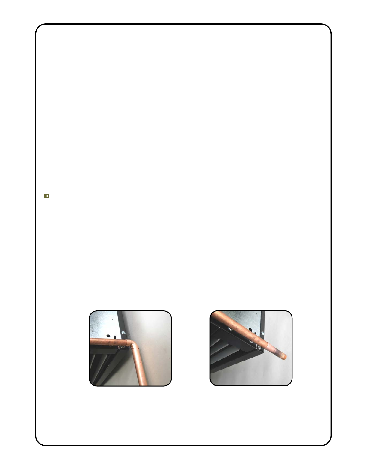
Ensure that when tightening the pipe connections onto the dry
cooling unit that pipe grips are used to hold the 1 inch steel bush of
each pipe connection to avoid damaging the copper coil inside the
unit, see picture opposite.
T9901018-1 Page 10 of 26
Install the expansion vessel, pressure relief valve, filling loop, pressure gauge, automatic
air vents, water dirt trap device, flow setter valve, drain valve(s), isolating valves and union
fittings for the removal of components. Installation pipework should be supported
independently from the cooling unit. The fitting of test points, e.g. binder, should be
considered for measuring pressures and temperatures. See Section ‘Design Information’
Page 3 and 4 for selection information on water pumps and flow setter valve.
The chilled water system needs to be cleaned using a suitable cleaning agent to ensure
that any flux residues/installation debris is removed (see BSRIA AG 1/2001.1). Fill the
chilled water system with water, vent air from the water system and thoroughly check the
whole system for water leaks. Once the system is ready add inhibitor to the correct
concentration. If necessary, the system should be protected against freezing and anti-
freeze should be added to the correct concentration.
NB. output may be reduced if antifreeze additives are used.
Fully insulate the chilled water system to prevent energy loss and to avoid condensation
dripping from chilled surfaces. External pipework, if used, must be weather-wrapped or
installed in suitable trunking.
Condensate Disposal System (Right hand side of unit)
As explained in Section ‘Design Information’ Page 3, the dry cooling unit is supplied with
an integral condensate drain tray and outlet pipe to drain condensate away from the unit in
an emergency condensate situation.
Remove the right hand plastic end cap by pulling off and connect a gravity condensate
drain pipe system to the 15mm copper drain pipe that protrudes from the right-hand rear of
the cooling unit. Extend this to a suitable drain or condensate pump (if required) outside of
the room that the dry cooling unit serves. Condensate pumps are not recommended but if
a gravity drain system is impossible and a condensate pump is the only alternative it must
not be fitted at the dry cooling unit because of reliability issues with these devices. If the
condensate needs to be pumped to a higher level with a condensate pump this should be
done in a separate room away from the server room. If there was a spillage of condensate
at the pump, therefore, it will not occur in the server room.
Make sure condensate pipework can be unclipped for when the drain tray needs to be
inspected and cleaned, see Page 22.
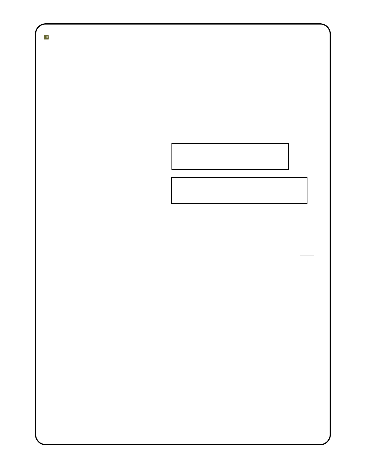
If using wall brackets use copper
elbow to extend drain pipe downwards If using hanging rods and there is
space to the rear the drain pipe can
extend backwards

T9901018-1 Page 11 of 26
If a condensate pump is being used the pump condensate sensor that starts/stops the
pump and indicates an alarm situation should be fitted in the metal fixing bracket at the
right hand end of the condensate drain tray within the unit. There is a rubber grommet with
9.5mm hole fitted in the fixing bracket which will accept a 10mm diameter condensate
sensor. Different size grommets can be fitted to suit other condensate sensors or if the
grommet is removed a larger condensate sensor can be located in the 13mm diameter
hole in the fixing bracket and held with silicon sealant. See also the manufacturer’s
instructions that come with the condensate pump for further information.
Condensate sensor fixing bracket at
RH end of drain tray with 9.5mm hole
grommet
Condensate sensor fixing bracket at
RH end of drain tray with grommet
removed to give 13mm hole
T9901018-1 Page 12 of 26
Electrical Supply to the Dry Cooling Unit (Left Hand Side of the Unit)
All electrical wiring and connections MUST be carried out by a competent
qualified electrician in accordance with the latest edition of the IEE wiring
regulations and/or local statutory regulations. (see also Wiring Diagram on Page
13)
A 2-pole local isolator having a contact separation of at least 3mm on both live and
neutral poles must be fitted in the 230V electrical supply to the Thermoscreens dry
cooling unit and located in an accessible position within 1m of the unit. This local
isolator will also serve as the On/Off switch for the fans inside of the cooling unit.
The unit must be connected using cables having an appropriate temperature rating
(heat resistant).
Ensure that the supply cables, circuit breakers and other electrical installation
equipment are correctly sized for the cooling unit.
0.5kW for cooling unit
Rated Electrical Power Input = +
kW rating of water pump installed
2.7A for cooling unit
Rated Current = +
Amps of water pump installed (max. 2A)
IMPORTANT: Please note that the water pump is supplied and fitted by the
installer and the electrical power consumption of it (kW and Amps) is entirely
dependent on which pump the installer selects, see Section ‘Design Information’
Page 3 & 4 for water pump selection. The electrical feed to operate the water
pump is a 230V/1ph/50Hz switched feed that comes from the dry cooling unit
(terminal Pu L), so the sizing of the electrical supply to the dry cooling unit must
also include for the pump as well.
NB. If the rated current of the water pump(s) is more than 2A an interface
relay/contactor will need to be used, powered from terminal Pu L, and the pump
electrical feed may then be from a separate electrical supply.
A 20mm size cable gland or conduit connector should be used for the
230V/1ph/50Hz Electrical Supply into the unit. See Figure 1, Page 8 showing
where the electrical supply enters the unit.
This appliance must be Earthed.
Connect the 230V/1ph/50Hz Electrical Supply to terminals L, N and Earth in the
dry cooling unit.

T9901018-1 Page 13 of 26
THERMOSCREENS PHV2000NT DRY COOLING UNIT
L3
Electrical Supply for
Outdoor Unit
230V/1ph/50Hz
or 400V/3ph/50Hz
Electrical Supply
230V/1ph/50Hz
24V AC
RELAY
24V
AC
240V
AC
Built In Thermostat
set to 30°C,
can be adjusted
between 10 - 35°C
Grey
Pink
Blue
Violet
Orange
Orange
Black
Red
Brown
Blue
Green/Yellow
Yellow
Yellow
Grey
T 8A
N
E
F2A
2
3
1
5
6
4
8
7
10
11
12
S2
S3 PUHZ-HW140VHA2/YHA2
OUTDOOR UNIT
S1
S3 S2
WATER
PUMP
M
1
L
FUSE
FUSE
MITSUBISHI PAC-IF010B-E PCB
TB61
TB142
8
7IN4
TB6
2-Core
Cable
CNX2 GRY
DIP SWITCH SETTINGS :-
SW1-1, 1-5, 1-6 ON Rest OFF
SW2- All OFF
SW3-1, 3-7 ON Rest OFF
SW6- Both OFF
TH1 RC
OPERATION
SIGNAL
Black
Remote ON/OFF
(Volt Free Input)
SITE WIRING
TB62
5
6
AB
Brown
Blue
PUHZ-HW140VHA2/YHA2 Unit
Error Signal (Volt Free Output)
FAN
MOTORS
SIEMENS RDG400
MANUAL ROOM
CONTROL
CN20 RED
Link Fitted
L2
L1 N E
CNS2
Mitsubishi sensor
fitted in pocket of flow
pipe on water coil
9
2-Pole Local
Isolator
ON/OFF Switch
Yellow
Black
White
SIEMENS QAH11.1
Return Air Sensor
FAN
HIGH
MED
LOW
M
1
Black
Blue
Red
White
Room Over Temperature Alarm [16(4)A at 230V]
10 to 11 contacts close on rising temperature
11 to 12 contacts open on rising temperature
TRANSFORMER
Pu L
Pu N
Pu E
White
S1
Brown
Brown
Brown
PAR-W21MAA
Not used for control
by the end user,
only needed so the
Outdoor Unit will run.
(Supplied and fitted
inside LH end cap)
DIPs :-
SW1-3 ON
Rest OFF
L
N
E230V/1ph/50Hz
2A maximum
2-Pole Local
Isolator
WARNING: 400V may exist between terminal S1 and other Live
terminals inside the Thermoscreens dry cooling unit
WIRING DIAGRAM – PHV2000NT DRY COOLING UNIT
T9901018-1 Page 14 of 26
Controls Wiring to the Dry Cooling Unit (Left Hand Side of the Unit)
All electrical controls wiring and connections MUST be carried out by a
competent qualified electrician in accordance with the latest edition of the IEE
wiring regulations and/or local statutory regulations. (see also Wiring Diagram on
Page 13)
The following connections need to be made, except where stated as optional. Use 20mm
size cable glands or conduit connectors:
Terminal on Dry Cooling Unit Terminal on SIEMENS RDG400
Manual Room Control
(use 0.5mm2max. cable size - small terminals)
1 G
2 G0
3 Y1
4 – for return air sensor in air intake M (do not wire if using air sensor inside RDG400)
5 – for return air sensor in air intake B1 (do not wire if using air sensor inside RDG400)
6 - optional DG (volt free input, for remote On/Off or
Run/Standby or Fire Alarm Circuit)
7 - optional D1 (ditto as above)
Terminal on Dry Cooling Unit Optional Error Signal Output Connection
8 Mitsubishi Electric heat pump system, Error Signal
(volt free contacts, rated 1A max, Error = Closed)
9
Terminal on Dry Cooling Unit Optional Room Over Temperature Alarm
Volt Free contacts rated at 16(4)A at 230V
(use 1.0mm2maximum cable size)
10 10 – 11 contacts close on rising temperature
11
12 11 – 12 contacts open on rising temperature
Terminal on Dry Cooling Unit Terminal on 230V/1ph/50Hz
Water Pump – 2A maximum
(use 1.5mm2maximum cable size)
Pu L L
Pu N N
Pu E E
Terminal on Dry Cooling Unit
(electrical supply and communications link
for interface pcb inside dry cooling unit)
Terminal on Mitsubishi Electric
PUHZ-HW140VHA/YHA2
(use 1.0mm2maximum cable size)
S1 S1
S2 S2
S3 S3
A local isolator to switch S1 and S2 On/Off is required within 1m of the dry cooling unit.
NB. The interface PCB is already Earthed via the supply to the dry cooling unit.
WARNING: 400V may exist between terminal S1 and other Live terminals inside the
Thermoscreens dry cooling unit.
The Mitsubishi Electric PUHZ-HW140 Outdoor Unit needs to be installed in accordance
with the relevant sections of the Mitsubishi Electric instructions supplied with the unit.
T9901018-1 Page 15 of 26
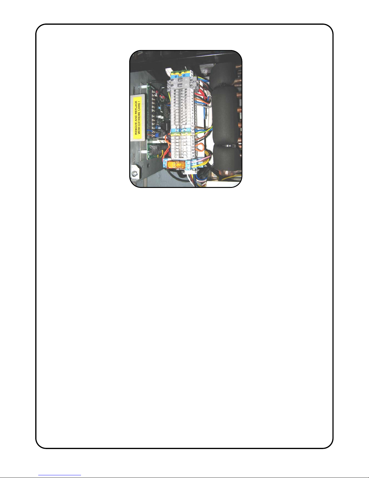
Once complete the electrical supply and controls wiring should appear as shown in the
picture:-
NB. For clarity the site wiring to terminals 6 to 12 for the optional items:
Remote ON/OFF
Mitsubishi Error Signal
Room Over Temperature Alarm
is not shown in this picture.
Please note: All the panels of the Thermoscreens dry cooling unit are covered in a
protective plastic film which should now be removed.

T9901018-1 Page 16 of 26
COMMISSIONING THE DRY COOLING UNIT
Ensure that the electrical supply to the Mitsubishi Electric Outdoor Unit and the
local electrical supply switch to the Thermoscreens Dry Cooling Unit are
switched off.
Chilled Water System Checks
The chilled water system must be commissioned by a qualified technician in accordance
with CIBSE Commissioning Code W, CIBSE KS9, BSRIA AG 2/89.3 and BSRIA AG
1.2001.1.
Check that the chilled water system has been cleaned using a suitable cleaning agent to
ensure that any flux residues/installation debris is removed (see BSRIA AG 1/2001.1).
Check that the chilled water system has been filled and the correct concentration of
inhibitor has been added.
If necessary, check that the system has been protected against freezing and that the
correct concentration of anti-freeze has been added.
Check that all water valves are open.
Check that air has been vented from the water system and thoroughly check the whole
system for water leaks – repair as necessary.
Dry Cooling Unit Checks
Check that the components inside the dry cooling unit are as shown in the picture below
Siemens
QAH11.1
Return Air
Sensor
(Black)
Interface
PCB
Room Over Temperature
Alarm Sensor (Silver)
Room Over Temperature
Alarm Thermostat
(
underneath the unit
)
24v AC
Relay
T9901018-1 Page 17 of 26
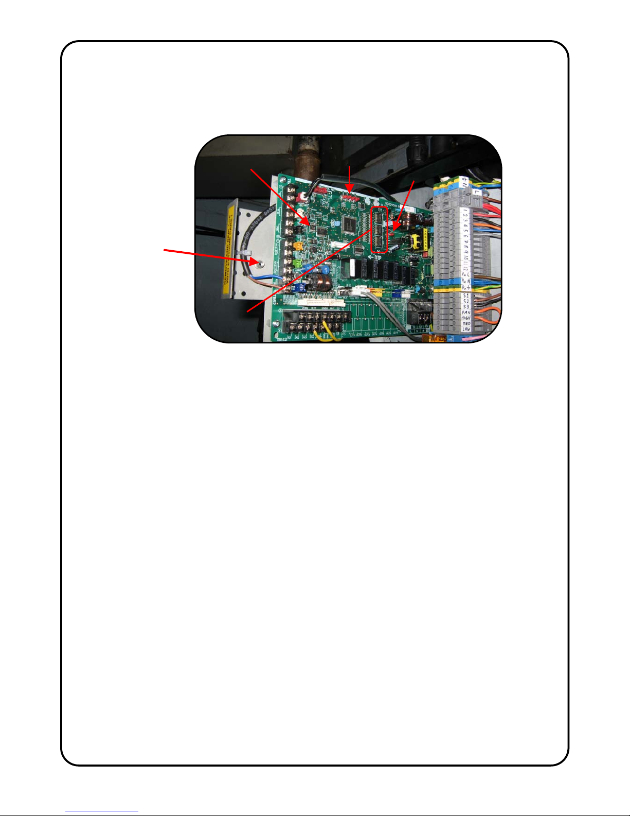
A Mitsubishi Electric Interface PCB is located within the left hand end of the
Thermoscreens Dry Cooling Unit to provide communication between the Outdoor Unit
and the Dry Cooling Unit. The Interface PCB on its mounting plate is held in place by a
fixing screw located in the left-hand end panel of the dry cooling unit under the left-hand
plastic end cap. Remove the screw and carefully slide the pcb partially out.
Check that the dip switches on the Interface PCB are set as follows:
SW1-1, 1-5, 1-6 ON; SW1-2, 1-3, 1-4, 1-7, 1-8 OFF
SW2 – All OFF
SW3-1, 3-7 ON; SW3-2, 3-3, 3-4, 3-5, 3-6, 3-8 OFF
SW6 – Both OFF
Room temperature control of the dry cooling unit is done via a Siemens RDG400 Manual
Room Control that is supplied with the unit. This room control is used to select the target
temperature (set point) of the room air temperature and to then switch the Mitsubishi
Electric cooling system On and Off to achieve this temperature.
If there is site wiring between terminals 4 & 5 in the dry cooling unit and terminals M & B1
in the Siemens RDG400 manual room control the room air temperature will be measured
using the black return air temperature sensor clipped onto the coil in the air intake of the
dry cooling unit. If there is no wiring from terminals 4 & 5 the room air temperature will be
measured in the RDG400 manual room control using its integral air temperature sensor.
Remove the RDG400 manual room control from its back-plate (2 screws at LH side of
control and pull at LH) and check that the dip switches in the control are set as follows:
SW1-3 ON
SW1-1, 1-2, 1-4, 1-5 OFF
Check that the wiring between the Thermoscreens dry cooling unit and the Siemens
RDG400 Manual Room Control, the water pump and, if used, the remote On/Off, error
signal and room over temperature alarm is in accordance with the Wiring Diagram on
Page 13.
Check that the S1, S2, S3 wiring between the Thermoscreens dry cooling unit and the
Mitsubishi Electric outdoor unit is in accordance with the Wiring Diagram on Page 13.
Fixing screw
(accessed from
end of dry
cooling unit) DIP
SW1
SW2
SW3
LED 1
DIP SW6 LED 3

T9901018-1 Page 18 of 26
Carefully slide the Interface PCB back into place if still withdrawn on its slide rails.
Ensure cables are not trapped inside and refit the fixing screw in the left hand end
panel.
Testing the Dry Cooling System
Ensure that the local electrical ON/OFF Switch/Isolator to the Thermoscreens dry
cooling unit is switched OFF !!
Switch on the S1, S2 local isolator adjacent to the Thermoscreens dry cooling unit.
Switch on electrical power to the Mitsubishi Electric Outdoor Unit.
WARNING! – Terminal S1 and the Mitsubishi Interface PCB inside the dry cooling unit
will now become Live with 230V electrical power from the outdoor unit !!
LED 1 on the Interface PCB should be lit to indicate power onto the PCB. Wait for the
PAR-W21MAA controller at the left hand end of the unit to initialize. The message
‘PLEASE WAIT’ will repeat on the screen of the PAR-W21MAA controller until
communication is set-up and the heat pump system is ready to operate. The PAR-
W21MAA controller will not respond to push button commands because of the dip
switch settings on the Mitsubishi Interface PCB. The outdoor unit must now be left
energised for 12 hours before carrying out any further operations.
Now switch on the local electrical ON/OFF Switch/Isolator to the Thermoscreens dry
cooling unit.
WARNING! – The fans inside of the dry cooling unit will now operate, beware of fast
spinning fans.
WARNING! – 400V may exist between terminal S1 and other Live terminals inside the
Thermoscreens dry cooling unit.
Check there is no mechanical noise coming from the fans and that both fans work.
If there is a Remote On/Off wired into terminals 6 & 7 on the dry cooling unit, switch this
On. Check that the LCD display screen on the Siemens RDG400 Manual Room Control
is working and lit-up. The display screen will be indicating the room temperature in large
numerals. Rotate the knob on the room control anti-clockwise and the numerals will
change to indicate the target (set-point) temperature. Set this target temperature at least
5°C below the room temperature. The numerals will then flash this target temperature 5
times and go back to showing the air temperature. At this point the water pump(s) will
start to operate and the outdoor unit will also start to work. The display on the PAR-
W21MAA controller will change to show that the outdoor unit is working and LED 3 on
the interface PCB should be lit to indicate the compressor in the outdoor unit is working.
Stop and start the water pump(s) by adjusting the target temperature up and down on
the manual room control to help bleed air out of the chilled water system. Ensure air is
bled out of the pump(s). If a flow setter valve is fitted check that the water flow rate of
the chilled water system is in accordance with Table 1, Page 3 or Table 2, Page 4.
After the system has been operating for a few minutes check that the chilled water
pipework is cooling down and the pipe temperature indicator on the PAR-W21MAA
controller (small numerals) shows a falling temperature. If the system is operating
correctly the pipe temperature should go down to 10°C. Check that cold air is being
discharged from the dry cooling unit across the whole length of the unit and that there is

T9901018-1 Page 19 of 26
no moisture forming on the surface of the cooling coil after at least 15 minutes of
operation at 10°C water flow temperature.
NB.If the outdoor unit has just been switched off via the controls it will require a few
minutes to start cooling again after the controls switch it back on.
If necessary adjust the angle of the outlet grille louvres in the air discharge of the dry
cooling unit to suit the air stream required in the room. Take care not to push objects
into the outlet grille.
Using the Siemens RDG400 manual room control take a mental note of the room air
temperature displayed on the screen and rotate the knob on the manual room control
clockwise and set the target temperature to above the room temperature. Check that
the water pump(s) and outdoor unit switches off. The fans in the dry cooling unit will
stay on.
Set the knob of the Room Over Temperature Alarm very high and using a multimeter
check that contacts 10 to 11 go open contact. Set the knob very low and check that
contacts 10 to 11 then go closed contact. Then set the knob to the setting that is
required by the operator to indicate there is a room over temperature alarm situation.
If a condensate disposal system has been installed check that it
operates correctly by filling the drain tray with some water and that
the water completely drains away from the unit. If a condensate
pump is being used ensure this is operating correctly and if possible
simulate a pump alarm fault condition to check that the alarm will
function. Some condensate pumps may require distilled water to do
this working test.
Switch off electrical power to the Thermoscreens dry cooling unit and the Mitsubishi
Electric outdoor unit. Replace the bottom access panel, air inlet grilles (with air filters)
and plastic end caps (see ‘To gain access inside the Dry Cooling Unit’, page 9). Switch
electrical power back on to the dry cooling unit and the outdoor unit and fully test all
operating parameters as above using the Siemens RDG400 manual room control.
Hand-over to End-User
Before leaving site it is important that there is a 'Hand-Over Meeting' to hand-over the
dry cooling system to the end user or their representative. This should include a full and
clear explanation of how the system operates and a demonstration showing the dry
cooling system running. Be sure to explain that the air inlet grilles and the air filters
inside the grilles must be regularly vacuum cleaned and the unit serviced at regular
intervals.
Fully explain and demonstrate the operation of the Siemens RDG400 Manual Room
Control. Also the remote On/Off, room over temperature alarm & Mitsubishi error signal,
if used. Explain that the fans in the Thermoscreens dry cooling unit can be switched off
in an emergency at the local electrical On/Off Switch/Isolator to the dry cooling unit.
Ensure that all instructions and manuals are handed to the end user or their
representative.
Fill tray with water

T9901018-1 Page 20 of 26
USER INSTRUCTIONS FOR THE DRY COOLING SYSTEM
For manual control using the Siemens RDG400 Manual Room Control
To Switch On and Off:
Make sure the On/Off Switch adjacent to the Thermoscreens dry cooling unit is
switched on. When it is switched on the fans in the dry cooling unit will operate
continuously.
The display screen on the manual room control will be indicating the air temperature in
large numerals.
Rotate the knob on the room control either clockwise or anti-clockwise and the numerals
will change and indicate the target (set-point) temperature as you rotate the knob.
Set this target temperature to the temperature required, say, 24°C.
The numerals will then flash this target temperature 5 times and go back to showing the
air temperature.
If the target temperature is lower than the air temperature the outdoor unit and the water
pump(s) will start to operate.
NB. If the outdoor unit has just been operating it will be necessary to wait several
minutes before it will restart again to provide chilled water.
Control of the room temperature will now be fully automatic and the dry cooling system
should be left to do its job. Fans will run continuously in the Thermoscreens dry cooling
unit and the outdoor unit and water pump(s) will automatically cut in and out to control
the room temperature.
If the On/Off Switch adjacent to the dry cooling unit is switched off the fans will turn off
and the outdoor unit and water pump(s) will not operate.
Siemens RDG400
M
a
n
ua
l R
oo
m
Co
n
t
r
o
l
Air Temperature
Knob
Target Temperature
(when flashing)
Table of contents
Popular Heat Pump manuals by other brands

Lennox
Lennox XP21 Series installation instructions

Nordyne
Nordyne T4BD-042 Series installation instructions

Quantum
Quantum 67ACW2-134 owner's manual

Bryant
Bryant LEGACY 223A installation instructions

Raypak
Raypak 2350 Series Installation & operating instructions

Airwell
Airwell XLM9 Installation and maintenance manual

Fujitsu
Fujitsu Waterstage WOYG140LCTA manual

atecpool
atecpool AMHP170 Installation instructions manual

DeLonghi
DeLonghi Bran 0011M H Installation, operating & service instructions

HKS lazar
HKS lazar HTi20 Installation & operation manual

Daikin
Daikin Super Multi NX FLXS25BAVMB Service Manual Removal Procedure

Baxi
Baxi AWHP 22 TR-2 Installation and service manual


