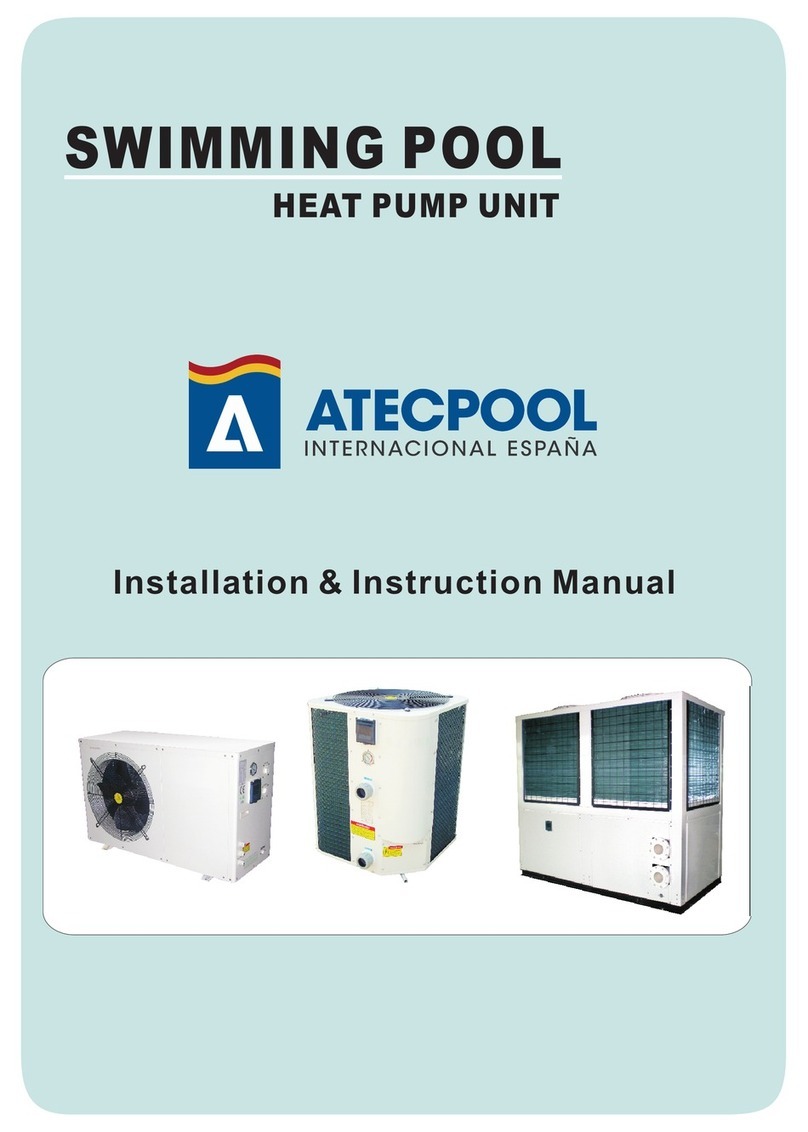
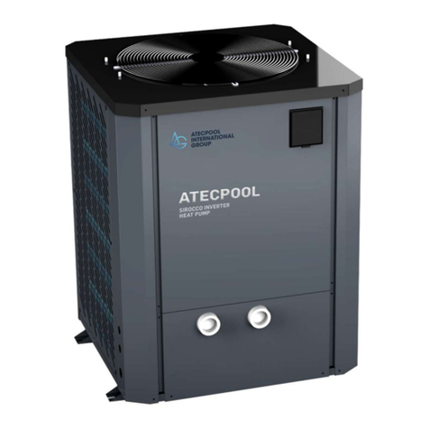
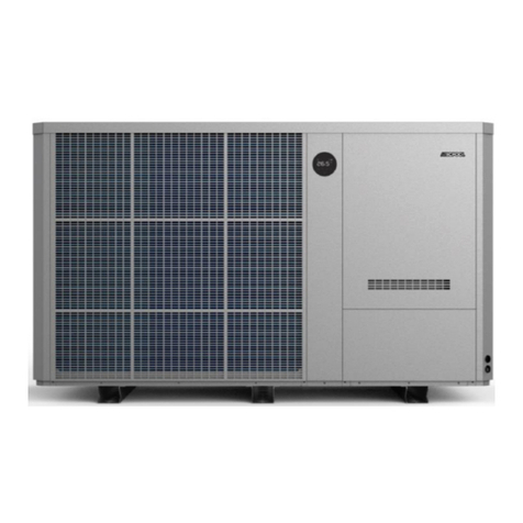
atecpool AMHP170 Service manual

SWIMMING POOL HEAT PUMP UNIT
Installation & Instruction Manual


CONTENTS
1. Preface
1.1 Preface
1.2 Safe precautions
2. Specifications
2.1 Performance Data of Swimming Pool Heat Pump Unit
2.2 Dimensions for Swimming Pool Heat Pump Unit
3. Installation and Connection
3.1 Installation of System
3.2 Swimming Pool Heat Pumps Location
3.3 How Close to Your Pool?
3.4 Swimming Pool Heat Pumps Plumbing
3.5 Swimming Pool Heat Pumps Electrical Wiring
3.6 Initial Start-up of the Unit
4. Usage and Operation
4.1 Function of the controller
4.2 Usage of the controller
4.3
4.4
4.5
5. Maintenance and Inspection
6.Appendix
6.1 Function of the controller
6.2 Usage of the controller
Parameter table
Running status table
Controller interface diagram and definition
1
1
2
3
3
4
5
5
6
6
7
8
8
9
9
11
22
22
23
24
25
25
26

1. PREFACE
In order toprovide our customerswith quality, reliability and versatility, this product has
been made tostrict production standards.This manual includes all the necessary
information about installation,debugging, discharging andmaintenance. Please readthis
manual carefully beforeyou open ormaintain the unit.The manufacture of this productwill
not be heldresponsible if someoneis injured orthe unit isdamaged, as aresult of
improper installation, debugging,or unnecessary maintenance.It is vitalthat the
instructions within this manual are adheredto at alltimes. The unit must beinstalled by
qualified personnel.
The unit canonly be repairedby qualified installercentre , personnelor an authorised
dealer.
Maintenance and operationmust be carriedout according tothe recommended timeand
frequency, as stated inthis manual.
Use genuine standardspare parts only.
Failure to complywith these recommendationswill invalidate the warranty.
Swimming Pool HeatPump Unit heatsthe swimming poolwater and keepsthe temperature
constant. For splittype unit, The indoor unitcan be Discretelyhidden or semi-hiddento
suit a luxuryhouse.
Our heat pumphas following characteristics:
1 Durable
The heat exchanger is madeof PVC &Titanium tubewhich can withstandprolonged
exposure to swimmingpool water.
2 Installation flexibility
The unit can be installedoutdoors or indoors.
3 Quiet operation
The unit comprises an efficient rotary/ scrollcompressor and alow-noise fan motor,
which guarantees itsquiet operation.
4 Advancedcontrolling
The unit includes micro-computer controlling,allowing all operationparameters to be
set. Operation statuscan be displayedon the LEDwire controller.Remote controller canbe
chosen as futureoption.
1
1.1 PREFACE

1. PREFACE
2
1.2 Safety precautions
ELECTRICAL POWER MUST BE SWITCHED OFF
BEFORE STARTING ANY WORK ON JUNCTION BOXES
The aim ofthis manual isto provide instructionsfor installation, commissioning,operation.
WARNING !
The installation, commissioningand
maintenance of thesemachines should be
performed by qualifiedpersonnel having a
good knowledge ofstandards and local
regulations, as wellas experience ofthis
type of equipment.
WARNING !
Any wiring producedon site mustcomply
with local electricalregulations.
WARNING !
Ensure that theelectrical supply
corresponds to thespecification indicated
on the unit'smaker's plate before
proceeding with theconnection in
accordance with thewiring diagram
supplied.
WARNING !
The unit mustbe EARTHED toavoid any
risks caused byinsulation defects.
WARNING !
No wiring mustcome in contact with the
heat source orthe fan rotating parts.
WARNING !
Preparation for shuttingdown the unit for a
prolonged period ifthe installation does
not contain glycol,the evaporator and the
chilled water pipesneed to be carefully and
completely drained ofwater.
WARNING!
In preparation forshutting down the unit for a
prolonged period thecondenser and the chilled
water pipes onthe reversible unit need to be
carefully flushed withfresh water( during 15
minutes by theoutlet) and then completely
drained of water.
Takecare !
The unit shouldbe handled using lifting and
handling equipment appropriateto the unit's
size and weight.
Takecare !
It is forbiddento start any work on the
electrical components withoutswitching off
the electrical supplyto the unit.
Takecare !
It is forbiddento start any work on the
electrical components ifwater or high
humidity is presenton the installation site.
Takecare !
When the unitis being connected, ensure that
no impurities areintroduced into the pipe
work and thewater circuits.
Takecare!
The setting watertemperature can not over 40
0
(105 F)to assure the unit running safety.
Takecare!
An insulated pipefor protection must be used for
the 3-core signalwire at the wire outlet for outdoor
installation.
Takecare!
Use copper supply wires.
The Manufacturer's warranty will not apply if the installation
recommendations listed in this manual are not followed.

3
2.SPECIFICATION
2.1 Performance data of Swimming Pool Heat Pump Unit
*** REFRIGERANT : R410A
Measurement conditions oftable :
Cooling: Outdoor airtemp:43 ,Inlet water temp:26
Heating:Outdoor air temp:27 ,Inlet water temp:26
Models, parameters, performancewill change forthe improvement ofproduct, please forgive
for
no especial notice.Specific parameters ison the baseof nameplate
Unit
Cooling Capacity Boost Mode)
Cooling Capacity
Cooling Power Input
Heating Capacity(Boost Mode)
Heating Capacity
Heating Power Input
Running Current
Power Supply
Compressor Quantity
Compressor
Fan Quantity
Fan Power Input
Fan Rotate Speed
Fan Direction
Noise
Water Connection
Water Flow Volume
Water Pressure Drop(MAX)
Unit Net Dimensions(L/W/H)
Unit Shipping Dimensions(L/W/H)
Net Weight/shipping Weight
kW
BTU/h
kW
BTU/h
kW
kW
BTU/h
kW
BTU/h
kW
A
W
RPM
dB(A)
mm
kPa
mm
mm
kg
3
m/h
see the drawingof the units
see package label
see nameplate/see packagelabel
AMHP170
96
327645
59.4-73.4
202673-250441
13.81-13.85
175
597269
28.2-130
96218-443560
1.76-20.97
47
2
Rotary
2
1300 2
850
vertical
63
110
45
25
380V/3N /50Hz

2.2 The dimensions for Swimming Pool Heat Pump Unit
2.SPECIFICATION
4
Model: AMHP170
unit mm
Airflow direction
110
110
1150
2130
434
174
454

3.1 Installation illustration
3.INSTALLATION ANDCONNECTION
5
Installation items:
The factory only provides the main unit andthe water unit;the other itemsin the illustration
are necessary spareparts for thewater system ,thatprovided by usersor the installer.
Attention:
Please follow thesesteps when usingfor the firsttime
1.Open valve andcharge water.
2.Make sure thatthe pump andthe water-in pipehave been filledwith water.
3.Close the valveand start theunit.
ATTN: It is necessarythat the water-inpipe is higherthan the poolsurface.
The schematic diagram is forreference only. Please check the water inlet/outlet label on the
heat pump whileplumbing installation.
Chlorinator cell
Water outlet
Pool
Valve
Water supply
Water inlet Water pump
Sand filter
(or other type filter)

3.2 Swimming Pool Heat Pumps Location
6
3.INSTALLATION ANDCONNECTION
The unit willperform well inany outdoor locationprovided that thefollowing three factorsare
presented:
1. Fresh Air - 2. Electricity - 3. Pool filter piping
The unit maybe installed virtuallyanywhere outdoors. Forindoor pools pleaseconsult the
supplier. Unlikea gas heater, it has no draft or pilot light problem in a windy area.
DO NOT place the unitin an enclosedarea with alimited air volume,where the units
discharge air willbe re-circulated.
DO NOT place the unitto shrubs whichcan block airinlet. These locations deny theunit of a
continuous source offresh air whichreduces it efficiency and mayprevent adequate heat
delivery.
Normally, the pool heatpump is installedwithin 7.5 metresof the pool.The longer the
distance from thepool, the greaterthe heat lossfrom the piping.For the mostpart ,the piping
is buried. Therefore, the heatloss is minimalfor runs ofup to15 meters(15meters to andfrom
the pump =30 meters total),unless the groundis wet orthe water tableis high.A veryrough
estimate of heatloss per 30meters is 0.6kW-hour,(2000BTU) for every 5 difference in
temperature between thepool water andthe ground surroundingthe pipe, whichtranslates to
about 3% to5% increase inrun time.
3.3 How Close To Your Pool?

3.4 Swimming Pool Heat Pumps Plumbing
Location: Connect theunit in thepool pump discharge(return) line downstreamof all filter
and pool pumps,and upstream ofany chlorinators, ozonatorsor chemical pumps.
Standard model haveslip glue fittingswhich accept 40mmNB PVC pipefor connection to
the pool orspa filtration piping.By using a50 NB to40NB you canplumb 50NB PVCpiping
Give serious considerationto adding aquick coupler fittingat the unitinlet and outletto allow
easy draining ofunit for winterizingand to provideeasier access shouldservicing be
required.
Condensation: Since theHeat pump coolsdown the airabout 4 -5 , water maycondense on
the fins ofthe horseshoe shapedevaporator. Ifthe relative humidityis very high,this could
be as muchas several litresan hour.The water will run downthe fins intothe basepan and
drain out throughthe barbed plasticcondensation drain fittingon the sideof the basepan.
This fitting isdesigned to accept20mm clear vinyltubing which canbe pushed onby hand
and run toa suitable drain.It is easyto mistake thecondensation for awater leak insidethe
unit.
NB: Aquick way toverify that thewater is condensationis to shut off the unit and keep the
pool pump running.If the waterstops running outof the basepan,it is condensation.AN
EVEN QUICKER WAYIS to TEST THE DRAIN WATER FOR CHLORINE- if theis no chlorine
present, then it'scondensation.
3.INSTALLATION AND CONNECTION
7
The Swimming PoolHeat Pumps exclusiverated flow titaniumheat exchanger requiresno
special plumbing arrangementsexcept bypass(please setthe flow rateaccording to the
nameplate). The water pressure dropis less than10kPa at max.Flow rate. Sincethere is no
residual heat orflame Temperatures, The unit does notneed copper heatsink piping. PVC
pipe can berun straight intothe unit.
To pool
From pump
PVC COUPLER
RECOMMENDED(Provided)

3.5 Swimming Pool Heat Pumps Electrical Wiring
NOTE: Althoughthe unit heatexchanger is electricallyisolated from therest of theunit, it
simply prevents theflow of electricityto or fromthe pool water. Grounding the unit is still
required to protectyou against shortcircuits inside theunit. Bonding isalso required.
3.INSTALLATION AND CONNECTION
3.6 Initial startup of the Unit
NOTE- In orderfor the unitto heat thepool or spa,the filter pump must be running to
circulate water throughthe heat exchanger.
Start up Procedure- Afterinstallation is completed,you should follow these steps:
1. Turnon your filterpump. Check forwater leaks and verify flow to and from the pool.
2. Turnon the electricalpower supply tothe unit, then press the key ON/OFF of wire
controller, Itshould start in several seconds.
3. Afterrunning a fewminutes make surethe air leaving the top(side) of the unit is
cooler(Between 5-10 )
4. With theunit operating turnthe filter pumpoff. The unit should alsoturn off automatically,
5. Allowthe unit andpool pump torun 24 hours per day until desired pool water emperature is
reached. When thewater-in temperature reachsetting, The unit just shuts off. The unit will
now automatically restart(as long asyour pool pumpis running)when the pool temperature
drops more than2 below set temperature.
Time Delay- The unit is equipped with a 3 minute built-in solid staterestart delay includedto
protect control circuitcomponents and toeliminate restart cycling and contactor chatter.
This time delaywill automatically restartthe unit approximately 3 minutes after each control
circuit interruption. Evena brief powerinterruption will activate the solid state 3 minute
restart delay andprevent the unitfrom starting untilthe 5 minute countdown is completed.
Power interruptions duringthe delay periodwill have no effect on the 3 minute countdown.
8
The unit hasa separate molded-injunction box with a standard electrical conduit nipple
already in place.Just remove thescrews and thefront panel, feed your supply lines in
through the conduitnipple and wire-nutthe electric supply wires to the three connections
already in thejunction box (fourconnections if threephase). To complete electrical hookup,
connect Heat Pumpby electrical conduit,UF cable or other suitable means as specified (as
permitted by localelectrical authorities) toa dedicated AC power supply branch circuit
equipped with theproper circuit breaker, disconnect ortime delay fuse protection.
Disconnect -A disconnectmeans (circuit breaker , fused or un-fused switch) should be
located within sightof and readilyaccessible from the unit, This is common practice on
commercial and residentialair conditioners andheat pumps. It prevents remotely-energizing
unattended equipment andpermits turning off power at the unit while the unit is being
serviced.

9
1.Function introduction of line controller
Main display area
1 Button function
No. Button
Icon
Button
Name Function
1
2
3
4
Power
On/off
Mode
Up
Down
Using for switchingmode
Using for chooseupper page orincrease values
Using for choosefollowing page ordecrease values
1
4
5
3
5
2
Time Using for timesetting and timingsetting
6
7
8
6
7
8
Tempunit
Switch Using for switchingbetween fahrenheit and celcius
Mute Using for turningon/off mute function, turn off timing
Low speed function.(referringto actual units)
Setting Using for tempsetting and savingsetting
Time display area
Supplementary
Display area
Using for poweron/off, cancel present operation
And back tothe last operation
4.USAGE AND OPERATION

10
Celcius Lighted on when the mainor auxiliary areadisplay degree
Centigrade parameter
Lighted on whenparameters are adjustable
2 Display function
Icon Meaning Function
Cooling
Heating
Automatic
Mode
Display at coolingmode
Display at heatingmode
Display at automaticmode
Water flow Display when themain area displays the rate of flow parameter.
Defrosting Lighted on whendefrosting
Water inlet
Water outlet
Lighted on whenmain display area shows inlet water temp
Lighted on whensupplementary display area shows outlet
water temp
Parameter category Lighted on whensupplementary display area shows parameter
Category
Minute
Fahrenheit Lighted on whenthe main or auxiliary area display degree
Fahrenheit parameter
Display when themain area displays minute parameter.
Setting
Parameter value Lighted on whenmain display area shows parameter value
Hour Display when themain area displays hour parameter.
Second Display when themain area displays second parameter.
Pressure Display when themain area displays pressure parameter.
Lock Display when keyboardis locked
Timing power on
Timing power off
Display when timingpower on started
Display when timingpower off started
Fault Display when fault occurs
Mute Display while thefunction or timing low speed is on
Compressor
Water pump
Fan motor
Display while thecompressor is on
Display while thewater pump is on
Display while thefan motor is on
4.USAGE AND OPERATION

4.2Usage of thecontroller
2.1 Power on/off
At thepower on state,press for 0.5s topower off, the screen displaysunits mode,
main display areashows OFF;
At thepower off state, press for 0.5s topower on, thescreen displays unitsmode,
main display areashows inlet watertemp, supplementary displayarea shows outletwater
temp.
Attention: power on/off operation couldonly be doneat power on/off main interface.
For example:
Press for
0.5 seconds to
power on/off
Mode
Present water
outlet temp
Mode Present water inlettemp
Power off main interface: Power on maininterface:
11
Screen out if1min
no operation
Present water
inlet temp
Press to back to
power on maininterface
Screen out if1min
no operation
System time
Press to back to
power off maininterface
2.2 Mode switch
At poweron/off main interface, continually press to circularly switch between
heating, cooling andautomatic mode.
ttentionA : If yourunits are singlecooling or singleheating type, themode switch isinvalid.
Press
for mode switch
Cooling mode Heating icon flashes
Heating icon keeps
lighted on after2s,
mode switch succeed.
4.USAGE AND OPERATION

12
Heating icon keepslighted on,
mode switch succeed.
2.3 Target temp setting
Youcan set suitablecooling target temp,heating target temp,automatic mode targettemp
(Targettemp default referringto parameter table)
Automatic modetarget temp: whenthe actual inletwater temp higher than the target temp,
the units startcooling; When theactual inlet watertemp lower thanthe target temp,the units
start heating(target tempdefault referring toparameter table)
press present mode targettemp flashes, press
to make thevalue increase. Press to make thevalue dncrease. Press to save the
setting and backto
Press will not savethe setting butget back to
Attention 20s no operation,the system willremember the parameter setting and back to
For example:
At power on/off main interface,
power on/off main interface
power on/off main interface.
Press to enter
target temp changepage
Heating target tempflashes
Heating mode Setting icon lightedon
Press to get back
Press
to save thesetting or
after 20s nooperation, it
automatically save thesetting
and get back.
Press for not
saving the setting
but get back
Press or
to revise
target temp value
4.USAGE AND OPERATION

13
At theadvanced user interface,you can setthe time ofsystem, switch thetemperature
from centigrade tofahrenheit, sound on/off, timer setting,status inquiry.
On the maininterface, press to entrance seniorinterface.
For example:
2.4.1 System time setting
At theadvanced interface, pressthe clock ,and the hourdigit start toflash,and then
press or to change thehour, press to save the change,use the same
way to changethe minute.
During the setting,press to exit systemtime setting andwill not savethe setting
before, if 20sno operation, thesystem will rememberthe setting automaticallyand back tothe
power on/off interface.
For example:
Press to entrance
senior user interface
Press to back or
back to maininterface
automatically
Power on maininterface:
Advanced user interface:
Power off main interface: Advanced user interface:
Press to enter
advanced user interface
Press to back or
back to maininterface
automatically
Press to
entrance the interface
of syst emtime setting
Press to back
or backing in20
seconds automaticlly
Hour digit flashes
Press
or
to setting the
hour place
2.4 Advanceduser interface
4.USAGE AND OPERATION

14
Minute digit flashes
Press to save hour
digit setting.
System time updatingfinished
Press to go back
Hour digit updated
Press to save
the setting ofhour
place
Hour digit flashes
Press to back Press or
to set the minute digit
Minute digit flashes
System time not updated
4.USAGE AND OPERATION

15
At theadvanced user interface,long press for 2s toenter timer 1power on setting
interface, ON 1in the timingdisplay area andthe time displayarea will flash(press
or to change betweenOFF 1, ON2, OFF 2and timing low speed,press , hour
digit flashes, thesetting method isthe same as 2.4.1 System timesetting . The ON1 power
on time oftimer 1 settingfinished, OFF 1will flash automatically, at thistime, the OFF1
ending time oftimer 1 canbe set, settingmethod is thesame as ON1.
If you donot need toset the OFF1power off time of timer1, after finishthe setting ofOn1
power on timeof timer 1,OFF1 flashes ,at this time,press to skip thesetting of OFF1
power off time of timer1and exit.
20s no operation,the system willremember the settingautomatically and backto the
power on/off interface.
Cancel the timing:it should bedone during thehour or minutedigit flashing state,press
, referring to2.4.3 for details.
For example:
2.4.2 Timing power on/off and timing low speed setting
1). Timing power on/off setting
Long press
for 2s
ON 1 and - -:- - flash
OFF 1 and - -:- - flash
Press can skip the
setting of ON1 to OFF 1
Press ,
hour digit flashes
Press to
go back
Hour digit flashes
Press
or
to change hour
digit
4.USAGE AND OPERATION

16
Hour digit flashes Hour digit lightedon,
minute digit flashes
Press to save
hour digit setting
minute digit flashes
automatically
Press
or to
change minute
digit
Minute digit flashes
Press to save
minute digit setting,
ON 2 flashes
automatically
Press to skip
ON 2 andother timing setting
OFF1 and timingicon light on,Timer 1power off time setting succeed.
The units willbe power off at 9:10automatically, meanwhile, OFF 1 and timing icon
light off. Timing power off mission accomplished.
2). Low speed timing and mute setting
,
At nightor break time,if the units noise bothered theresting, low speed timing and mute
function can beturned on.
At theadvanced users interface,long press for 2s toenter timer 1power on
setting interface. ON1 in thetiming display areaand the time display area will flash, press
for 4 timesto change totiming low speedstart time setting, press again to
change to timinglow speed endingtime setting, press , hour digitflashes, method is
the same as Timing power on/off setting .Cancel timing low speed setting: at the advanced
user interface, press can cancel timinglow speed setting
4.USAGE AND OPERATION

17
Long press
for 2s
ON 1and - -:- - flash
ON and - -:- - flash
Press for 4 times
skip the ON1 OFF 1
ON 2 OFF 2 settingto
low speed ONsetting
Press and
hour digit flashes
Press to go
back
Hour digit flashes
Press
or to
revise hour digit
Mute icon lighted on
Hour digit flashes
Press to
save hour digit
setting, minute digit
flashes automatically
Hour digit keeps
lighted on minute
digit flashes
Press
or to revise
minute digit
Press to save
minute digit setting
low speed OFF
flashes automatically
The setting oflow speed OFF is the same as low speedON
4.USAGE AND OPERATION
Table of contents
Other atecpool Heat Pump manuals
Popular Heat Pump manuals by other brands

Amana
Amana P68855-8C owner's manual

Panasonic
Panasonic WH-SDF03E3E5 Design handbook

Bryant
Bryant 549B Series Installation, Start-Up and Service Instructions

Trane
Trane WPHF Installation and owner's guide

AIRSYS
AIRSYS COM4T CV36H2A Series Installation and operation manual

Thermor
Thermor PREMIUM Series manual

Pentair
Pentair ThermalFlo 1200R H/C brochure

Daikin
Daikin EBLA09DAV3 User reference guide

Panasonic
Panasonic WH-UD09JE5 operating instructions

Daikin
Daikin Altherma 3 HT Installer's reference guide

BSVILLAGE
BSVILLAGE Hayward Micro Installation instructions manual

Daikin
Daikin VRV IV HXHD125AV1B Operation manual