1. PREFACE
In order to provide our customers with quality, reliability and versatility, this product has
been made to strict production standards. This manual includes all the necessary
information about installation, debugging, discharging and maintenance. Please read this
manual carefully before you open or maintain the unit. The manufacture of this product will
not be held responsible if someone is injured or the unit is damaged, as a result of
improper installation, debugging, or unnecessary maintenance. It is vital that the
instructions within this manual are adhered to at all times. The unit must be installed by
qualified personnel.
The unit can only be repaired by qualified installer centre , personnel or an authorised
dealer.
Maintenance and operation must be carried out according to the recomended time and
frequency, as stated in this manual.
Use genuine standard spare parts only.
Failure to comply with these recommendations will invalidate the warranty.
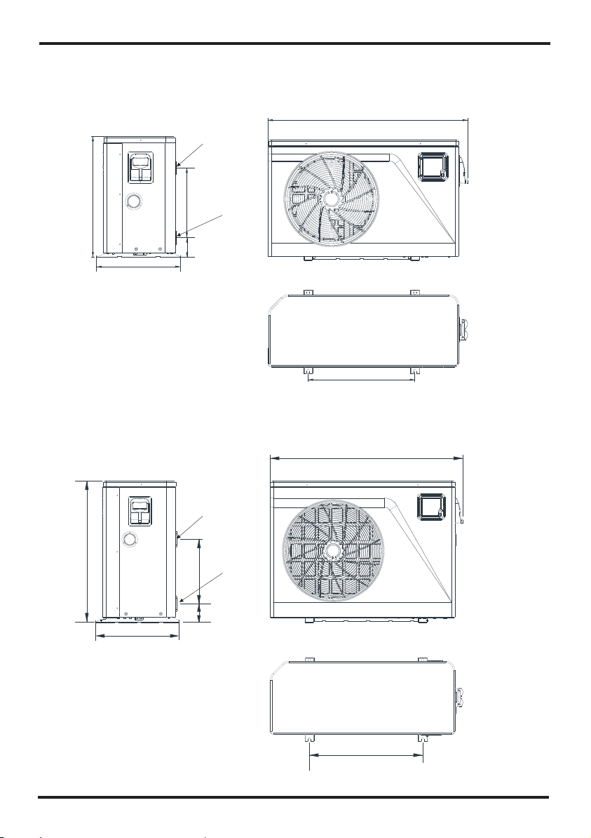
Swimming Pool Heat Pump Unit heats the swimming pool water and keeps the temperature
constant. For split type unit, The indoor unit can be Discretely hidden or semi-hidden to
suit a luxury house.
Our heat pump has following characteristics:
1 Durable
The heat exchanger is made of PVC & Titanium tube which can withstand prolonged
exposure to swimming pool water.
2 Installation flexibility
The unit can be installed outdoors.
3 Quiet operation
The unit comprises an efficient rotary/ scroll compressor and a low-noise fan motor,
which guarantees its quiet operation.
4 Advanced controlling
The unit includes micro-computer controlling, allowing all operation parameters to be
set. Operation status can be displayed on the LCD wire controller. Remote controller can be
chosen as future option.
1
WARNING
Do not use means to accelerate the defrosting process or to clean,
Other than those recimmended by the manufacturer.
The appliance shall be stored in a room without continuously
operating ignition sources (for example:open flames, an
operating gas appliance or an operating electric heater.)
Do not pierce or burn.
Be aware that refrigerants may not contain an odour,
Appliance shall be installed,operated and stored in a room with a floor area larger than 30㎡
.
NOTE The manufacturer may provide other suitable examples or may provide additional
information about the refrigerant odour.
This appliance can be used by children aged from 8 years and above and persons
with reduced physical, sensory or mental capabilities or lack of experience and
knowledge if they have been given supervision or instruction concerning use of the
appliance in a safe way and understand the hazards involved. Children shall not play with
the appliance. Cleaning and user maintenance shall not be made by children without
supervision.
The appliance shall be installed in accordance with national wiring regulations.
If the supply cord is damaged, it must be replaced by the manufacturer, its service agent or
similarly qualified persons in order to avoid a hazard.
Before obtaining access to terminals, all supply circuits must be disconnected.
Do not operate your air conditioner in a wet room such as a bathroom or laundry room.
An all-pole disconnection device which has at least 3mm clearances in all poles , a n d
have a leakage current that may exceed 10mA, t h e residual current device (RCD) having
a rated residual operating current not exceeding 30mA, a n d disconnection must be
incorporated in the fixed wiring in accordance with the wiring rules.
1. PREFACE
2
Do not use means to accelerate the defrosting process or to clean, other than those
recommended by the manufacturer
The appliance shall be stored in a room without continuously operating ignition sources (for
example: open flames, an operating gas appliance or an operating electric heater.)
Do not pierce or burn
Appliance shall be installed, operated and stored in a room with a floor area larger than 30
m2
Be aware that refrigerants may not contain an odour.
The installation of pipe-work shall be kept to a minimum 30 m2
Spaces where refrigerant pipes shall be compliance with national gas regulations.
Servicing shall be performed only as recommended by the manufacturer.
The appliance shall be stored in a well-ventilated area where the room size corresponds to
the room area as specified for operation.
All working procedure that affets safety means shall only be carried by competent persons.
Transport of equipment containing flammable refrigerants
Compliance with the transport regulations
Marking of equipment using signs
Compliance with local regulations
Disposal of equipment using flammable refrigerants
Compliance with national regulations
Storage of equipment/appliances
The storage of equipment should be in accordance with the manufacturer's instructions.
Storage of packed (unsold) equipment
Storage package protection should be constructed such that mechanical damage to the
equipment inside the package will not cause a leak of the refrigerant charge.
The maximum number of pieces of equipment permitted to be stored together will be
determined by local regulations.