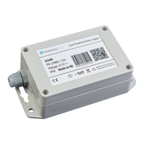
ThingsLog LPMDL-1102 User manual

Access to CLI console port
To access the command line interface you have to connect with an USBtoTTL cable to the
logger console (UART) port.
To access the console port on the loggers you have to take out the logger from the enclosure
turn it upside down and connect to the 3 pins on the other side of the PCB.
The inputs are GND, TX and RX as it is shown on the picture.
Figure 1 UART & service mode pins in 4 channel data loggers (v.4.2)

To put the device into service mode you need to short circuit the two pins close to the reed
switch, see on the picture the “Service pin” and “Service GND”.
If you are using ThingsLog UART cable the color scheme is the following:
Black
GND
White
RXD
Green
TXD
Red
5V (not used)
Note: RX on the cable must be connected to TX on the board and RX on the cable must be
connected with TX on the board.
CLI commands
There are different commands that can be used to configure the GPRS device when it is in
service mode. In order to do this configuration it is necessary to put device in service mode
using the service button.
Enter in base service mode
1. Connect to the debug UART port using baud rate 9600
2. Press the service button
3. Verify that the following message appear in UART console: "service # ". This indicates
that the device is in the base service mode
Example
service #
Enter in gprs_service mode
1. Execute extension command. This will enter in device (LoRA, GPRS, NBIoT) specific
sub-menu
2. Verify "gprs_service # " prompt appears.
Example
service # extension
gprs_service #
Exit the gprs_service mode and enter in base service mode
1. Verify you are in gprs_service mode - the prompt is "gpr_service # "
2. Execute exit command to exit "gprs_service" mode and to enter the base service mode
3. Verify "service # " prompt for the base service mode appear

Example
gprs_service # exit
service #
Set collecting server address and port
1. Verify you are in gprs_service mode - the prompt is "gpr_service # "
2. Execute command set_addr_port
3. Verify "address=" prompt appear
4. Enter the new server address and press enter
5. Verify "port=" prompt appear
6. Enter the new server port and press enter
7. Execute resolveIp to set DNS name resolution 8 Verify that resolveIp= appears. Set it
1 to resolve address by DNS or 0 to disable resolving (address should be an IP
address).
8. Verify "done" appear
Example:
service # extension
gprs_service # set_addr_port
address=10.10.10.10
port=4445
resolve_ip=1
done
gprs_service #
Get collecting server address and port
1. Verify you are in gprs_service mode - the prompt is "gpr_service # "
2. Execute command get_addr_port
3. Verify "address=<some_ip>" appear
4. Verify "port=<some_port>" appear
Example:
service # extension
gprs_service # get_addr_port
address=10.10.10.10
port=4445
done
gprs_service #
Set APN
1. Execute command set_apn
2. Verify "apn=" prompt appears
3. Enter the new APN and press enter
4. Verify "done" appear

Example:
service # extension
gprs_service # set_apn
apn=some.operator.apn
done
gprs_service #
Get APN
1. Execute command get_apn
2. Verify "apn=some.operator.apn" appear
Example:
service # extension
gprs_service # get_apn
apn=some.operator.apn
done
gprs_service #
Store configuration
1. Verify you are in base service mode - the prompt is "service # "
2. Execute "store" command to save the configurations
3. Verify "service # " prompt appear
Example:
service # store
service #
Load configuration
1. Verify you are in base service mode - the prompt is "service # "
2. Execute load command to load the configurations
3. Verify "service # " prompt appear
Example:
service # load
service #
Get device number
1. Verify you are in base service mode - the prompt is "service # "
2. Execute number command to get the device number
3. Verify "number=00000001" hex device number appear
Example:

service # number
number=00000001
service #
Set device number
1. Verify you are in base service mode - the prompt is "service # "
2. Execute set_n command to set the device number
3. Verify "number=" prompt appear
4. Enter the new device number 0x + (8 hex digits) and press enter
5. Verify that "done" appears
Example:
service # number
number=0x00000001
Done
service #
Get firmware version
1. Verify you are in base service mode - the prompt is "service # "
2. Execute version command to get the firmware version
3. Verify "version=<some_version>" appear
Example:
service # version
version=0x0604bbc1
service #
Get date
1. Verify you are in base service mode - the prompt is "service # "
2. Execute date command to get the current date
3. Verify "date=<some_date>" appear
Example:
service # date
date=2017-04-01 12:40:00
service #
Set date
1. Verify you are in base service mode - the prompt is "service # "
2. Execute set_d command to set the device number
3. Verify "date=" prompt appear
4. Enter the new date in format YYYY-MM-dd HH:mm:ss
5. Verify "done" appear

Example:
service # set_d
Date=2017-04-01 12:40:00
Done
service #
Get current initial config
1. Verify you are in base service mode - the prompt is "service # "
2. Get current config by executing configure.
Example:
Example:
*** Config ***
2018-09-03 12:03:04
-----------
digits1=8
digits2=8
count_init1=1
count_init2=1
record_period=0
every=1
counts_threshold=300
sensors=01: CNT1
-----------
Description of configuration parameters
Name
Default
Value
Possible values
Description
digits1
8
Min value: 1
Max value: 9
Total number of
countable digits on the
display of the meter for
the first pulse input
digits2
8
Min value: 1
Max value: 9
Total number of
countable digits on the
display of the meter for
the second pulse input
count_init1
1
Max value depends on the digits1
value
The value of the meter
display of the first pulse
input
count_init2
1
Max value depends on the digits1
value
The value of the meter
display of the second
pulse input
record_period
0
0 –MINUTES
1 –HOURS
The value of the record
period 0 mean minutes
every
1
Min value: 1
Max value: 127
The value in record
period (1 - every 1
minute

counts_threshold
300
Min value: 1
Max value: 256
How many counters to
keep in memory
sensors
01
Mask of 4 bits
0x000001 –Pulse sensor 1
0x000010 –Pulse sensor 2
0x000100 –Current sensor 1
0x001000 –Current sensor 2
0x010000 –On/Off sensor 1
0x100000 –On/Off sensor 2
Which input is active, 01
means the first pulse
input
Set initial config
1. Verify you are in base service mode - the prompt is "service # "
2. Execute set_conf and enter the configuration menu
service # set_conf
config # help
commands:
help
set_count_init1
set_count_init2
set_digits1
set_digits2
set_rec_period
set_every
set_counts_threshold
set_sensors
save
exit
3. Set inputs reading frequency. Execute set_every
config # set_every
set_every= 3
4. Enable sensor input port
config # set_sensors
sensors= 1
5. Set counts threshold (the number of counters to be gathered prior transmission attempt).
Execute set_counts_threshold If the transmission is successful all counters will be
deleted from memory. If transmission fails counters will be kept in memory and will be
re-transmitted on next attempt. If memory got full the oldest counters will be deleted first.
config # set_counts_threshold
counts_threshold= 100
6. Set counter value. Has to be set all meaningful digits up to the magnet pointer. Execute
set_count_init1 for the first input and set_count_init2 for the second.

config # set_count_init1
count_init1= 123
config # set_count_init2
count_init2= 234
7. Save and apply the configuration. Execute save
config # save
Save config
Applying config
Config Counters
rec_conf, size=102, rec_size=2, buff_size=206
Alarm enabled
service #
Set NB-IoT radio frequency bands
1. Enter service mode
2. Enter modem mode and enter the following commands. The AT+NBAND command is
critical. You can enable one or more bands simultaneously. The more bands you enable
the more time the model will require in order to attach to scan the radio and attach to the
network
service # modem
Type help for help
Boot: Unsigned
Security B.. Verified
Protocol A.. Verified
Apps A...... Verified
REBOOT_CAUSE_SECURITY_PMU_POWER_ON_RESET
Neul
OK
AT+CFUN=0 -> Power down the radio module
OK
AT+NBAND=5,8 -> Set one ore more frequency bands
OK
AT+CFUN=1 -> Power up the radio module
OK
exit
Exit service modem
Turning off GPRS
GPRS is turned off
Other manuals for LPMDL-1102
1
Table of contents
Other ThingsLog Data Logger manuals
Popular Data Logger manuals by other brands
Beko
Beko METPOINT OCV Instructions for installation and operation

MadgeTech
MadgeTech CurrentX Series Product user guide

MadgeTech
MadgeTech QuadVoltV2 Product user guide

Inductosense
Inductosense WAND user manual

Reed Instruments
Reed Instruments R8100SD instruction manual
Dickson
Dickson PR120 quick start guide
Campbell
Campbell CR510 Operator's manual
Measurement Computing
Measurement Computing USB-500 Series Getting started
UniData Communication Systems
UniData Communication Systems Starlog Prologger 7001 user manual
cloudworks
cloudworks CDS552 user manual
Ahlborn
Ahlborn ALMEMO 3290-8 V5 operating instructions
PCE Instruments
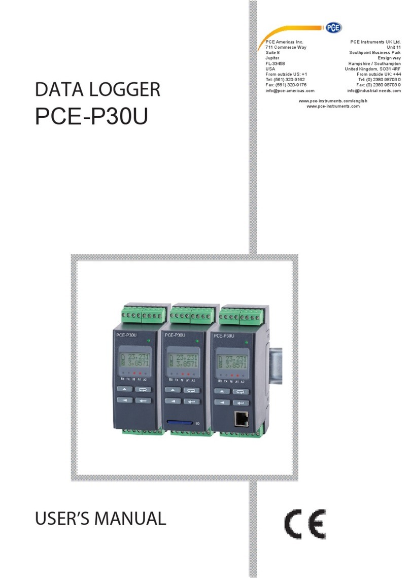
PCE Instruments PCE-P30U user manual

