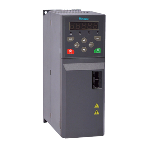
Thinkvert TI120 Series User manual

THINK DRIVES THE WORLD
TI120 Series VFD
User Manual

User Manual of TI120 Series Variable Frequency Drive
Preface
First of all, thank you for purchasing and using the TI120 Series Variable Frequency Drive developed by
Thinkvert Technology Limited.
TI120 series variable frequency drive is a general high-performance current vector variable frequency
drive, which can be used for controlling AC asynchronous motor and synchronous motor. TI120 series
adopt high-performance vector control technology to realize low speed and high torque output and has
good dynamic characteristics and super overload capability. Through fast current control and voltage
control technology, smooth and fast acceleration and deceleration characteristics are realized. It can be
used for driving machine tools, cranes, paper-making, textile, printing, packing, food, fan, pumps and
various automatic production equipment.

User Manual of TI120 Series Variable Frequency Drive
Brief Introduction Of TI120 Series VFD
Functions and Features
Compared with common products in the same industry, the product has smaller structure volume
and larger power density.
Design of wide voltage range: rated input three-phase AC 360-460V, wide voltage range can
reach 323V-528V.
Built-in DC reactor: built-in DC reactor of 160 kW~450 kW model.
More perfect built-in brake unit: built-in brake unit below 37kW, 37kW~132kW optional built-in
brake unit.
Fast and smooth wave-by-wave current limiting function can avoid over-current faults of frequent
variable frequency drive.
The perfect over-excitation function can inhibit the rise of bus voltage during deceleration process
effectively, avoid frequent reporting of over-voltage fault and realize fast braking under the
condition of not connecting the brake resistor.
V/F separation function can realize the using requirements of variable-frequency power source.
Perfect complete machine protection function, short-circuit protection to ground, output
short-circuit protection, short-circuit protection of various power supplies, etc.
Precautions for Use
For users who use this product for the first time, they shall carefully read this manual firstly. If they
have any questions about some functions and performance, please consult our technical
personnel for timely help so as to use this product conveniently, quickly and correctly.
Unpacking Inspection
When unpacking, please carefully confirm whether the model of the nameplate of this machine
and the rated value of the variable frequency drive are consistent with your order. The box
contains the machine you ordered (attached product certificate) and user manual (attached
product warranty card). Whether the products are damaged during transportation; if any omission
or damage is found, please contact our company or your supplier to solve it immediately

User Manual of TI120 Series Variable Frequency Drive
Safety Precautions
Safety Statement
Please read carefully and observe the safety precautions when installing, operating and
maintaining the product.
To ensure personal and equipment safety, when installing, operating and maintaining the product,
please follow all safety precautions indicated on the product and the manual.
The "precautions" and "danger" items in the manual do not represent all safety items that should
be followed, but only supplement all safety precautions.
This product shall be used in an environment that meets the design specification requirements,
otherwise it may cause faults, and functional abnormalities or component damage caused by
failure to comply with relevant regulations are not within the scope of product quality assurance.
Our company will not bear any legal liability for personal safety accidents and property losses
caused by violation operation of the products.
Definition of Safety Level
"Danger" means death or serious personal injury if you do not follow the regulations.
"Notice" means that if you do not follow the regulations, it may cause minor physical injury or
equipment damage.
Safety Precautions
■ Before installation
Danger
Do not touch control terminals, single board components and variable frequency drive
components with your hands directly!
Please do not use the variable frequency drive with missing or damaged components;
otherwise there is a risk of failure expansion and personal injury!
Note
Whether the rated value of the product nameplate is consistent with your order
requirements, if not, please do not install it!
Please do not install when the packing list is not consistent with the actual object.

User Manual of TI120 Series Variable Frequency Drive
■ Installation
Danger
Installation must be carried out by qualified personnel, otherwise there is a risk of electric
shock!
The variable frequency drive shall be installed on metal or other flame retardant objects,
otherwise there is fire danger!
The installation of the variable frequency drive shall be far away from flammable objects
and heat sources, otherwise there is fire danger!
The variable frequency drive can not be installed in an environment containing explosive
gas, otherwise there is a risk of explosion!
Do not twist the fixing bolts of equipment components at will, especially the bolts marked
with red, otherwise there is a risk of equipment damage!
Note
It shall be handled gently, and the bottom plate of the product is held to prevent foot injury
or variable frequency drive damage!
Please install it in a place that can bear the weight of the variable frequency drive,
otherwise there is risk of equipment damage and personal injury when falling!
Please confirm that the installation environment meets the requirements of section 2.2.1. If
it cannot meet the requirements, it shall be derated or cannot be used; otherwise, it may cause
equipment failure or damage!
Avoid dropping drilling residues, thread ends and screws into the variable frequency drive
during installation; otherwise it may cause failure of variable frequency drive.
When the variable frequency drive is installed in the cabinet, heat dissipation shall be
properly handled; otherwise it may cause product failure or damage!
■Wiring
Danger
Wiring must be carried out by qualified personnel; otherwise there is a risk of electric
shock or equipment damage!
Strictly follow this manual during wiring; otherwise there is a risk of electric shock or
equipment damage!
Only when the input power supply is completely disconnected can wiring be carried out,
otherwise there is a risk of electric shock!

User Manual of TI120 Series Variable Frequency Drive
All wiring and circuits shall meet the requirements of EMC and safety standards. Please
refer to the recommendations in this manual for wire diameter, otherwise accidents may occur!
The leakage current of the whole variable frequency drive may be more than 3.5mA. In
order to ensure safety, the variable frequency drive and the motor must be grounded;
otherwise there is a risk of electric shock!
It must be wired in strict accordance with the screen printing of variable frequency drive
terminals, it is forbidden to connect the three-phase power supply to the output terminals U, V
and W, otherwise there is a risk of equipment damage!
Please install the brake resistor at B1 and B2/+ ends correctly, and do not connect to other
terminals, otherwise there is a risk of equipment damage!
Main circuit terminal wiring screw bolts must be tightened; otherwise there is a risk of
equipment damage!
It is forbidden to connect AC 220V voltage grade signals to terminals other than control
terminals R1A, R1B,R1C, and R2A, R2B and R2C; otherwise there is a risk of equipment
damage!

User Manual of TI120 Series Variable Frequency Drive
Note
All our products have been subjected to withstand voltage test before leaving the factory. It
is forbidden to conduct this test on the variable frequency drive; otherwise there is a risk of
equipment damage!
Terminal signal lines of the variable frequency drive shall be far away from main power
line, and they be vertically crossed under the condition that the distance cannot be guaranteed,
otherwise the control signals shall be interfered!
When the length of motor cable is more than 100m, it is recommended to select output
reactor, otherwise there is a risk of equipment failure!
The encoder must use shielded cable and the shielding layer must be grounded correctly!
■ Operation
Danger
If the storage time of the variable frequency drive exceeds 2 years, the voltage regulator
shall be applied to boost the voltage gradually, otherwise there is a risk of equipment damage!
After the wiring is finished according to the requirements of section 2.3, the variable
frequency drive can only be powered on; otherwise there is a risk of equipment damage or
electric shock!
After the variable frequency drive wiring is confirmed to be correct, the power can only be
turned on after the cover plate is covered. It is forbidden to open the cover plate after the power
is turned on; otherwise there is a risk of electric shock!
After the variable frequency drive is powered on, do not touch the variable frequency drive
and its peripheral circuits regardless of the state of the variable frequency drive, otherwise
there is a risk of electric shock!
Before running the variable frequency drive, it must check there is no person in
surrounding area who can reach the motor so as to prevent personal injury.
During the operation of the variable frequency drive, foreign matters shall be avoided from
falling into the equipment; otherwise there is a risk of equipment damage!
Non-professional technicians are forbidden to test signals during operation, otherwise
there is a risk of personal injury or equipment damage!
Do not change variable frequency drive parameters at will; otherwise there is a risk of
equipment damage!
Note
Please confirm whether the number of phases and rated voltage of the power supply are

User Manual of TI120 Series Variable Frequency Drive
consistent with the nameplate of the product, otherwise equipment damage may be caused!
Check whether there is short circuit in the peripheral circuit connected to the variable
frequency drive and whether the wiring is tight, otherwise the equipment damage may be
caused!
Before operation, please make sure that the motor and machinery are within the allowable
range of use, otherwise the equipment may be damaged!
It is forbidden to touch the fan, radiator and brake resistor directly; otherwise there is a risk
of mechanical damage and scalding!
Do not control the start and stop of the variable frequency drive frequently by switching on
and off, otherwise there is a risk of equipment damage!
Before switching on/off the variable frequency drive output switch or contactor, it must
make sure that the variable frequency drive is in a no-output state, otherwise there is a risk of
equipment damage!
■ Maintenance
Danger
Product maintenance, inspection or replacement of parts must be carried out by engineers
with professional qualifications!
It is forbidden to maintain, inspect or replace parts of the product with electricity; otherwise
there is a risk of electric shock!
It must wait for 10 minutes at least after power failure to ensure the residual voltage of
electrolytic capacitor drops below 36V before maintaining, inspecting or replacing the parts!
After replacing the variable frequency drive, it must be executed again in strict accordance
with the above procedures!
Note
When maintaining, inspecting or replacing the parts, it shall not touch the part body;
otherwise there is a risk of electrostatic damage to the part!
All pluggable devices can only be plugged and unplugged when power is off!

User Manual of TI120 Series Variable Frequency Drive
Contents
Chapter 1 Product Information.......................................................................................................................... - 1 -
1.1 Product Naming............................................................................................................................................- 1 -
1.2 Description of Product Nameplate........................................................................................................... - 1 -
Chapter 2 System Installation and Wiring..................................................................................................... - 2 -
2.1 Peripheral system connection diagram...................................................................................................- 2 -
2.2 Installation......................................................................................................................................................- 3 -
2.2.1 Installation environment.................................................................................................................... - 3 -
2.2.2 Installation space and direction....................................................................................................... - 3 -
2.3 Wiring..............................................................................................................................................................- 5 -
2.3.1 Standard wiring diagram................................................................................................................... - 5 -
2.3.2 Functional description of main circuit terminal.............................................................................- 5 -
2.3.3 Terminal screw and wiring specifications...................................................................................... - 8 -
2.3.4 Wiring note of main circuit................................................................................................................ - 9 -
2.3.5 Control unit.........................................................................................................................................- 10 -
Chapter 3 Keyboard Operation and Trial Operation.................................................................................- 18 -
3.1 Instructions of Operating Keyboard.......................................................................................................- 18 -
3.1.1 Key function of operation keyboard..............................................................................................- 18 -
3.1.2 Description of operating keyboard indicator light...................................................................... - 20 -
3.1.3 Examples of keyboard operation.................................................................................................. - 20 -
3.2 Basic Operation and Trial Operation..................................................................................................... - 21 -
3.2.1 Identification of motor parameter.................................................................................................. - 21 -
3.2.2 Selection of motor control mode................................................................................................... - 21 -
3.2.3 Start and stop commands and modes.........................................................................................- 22 -
3.2.4 Frequency source selection........................................................................................................... - 23 -
Chapter 4 Parameter List...................................................................................................................................- 25 -
Chapter 5 Detailed parameter introduction.................................................................................................- 77 -
Chapter 6 Fault Diagnosis and Countermeasures................................................................................. - 136 -
6.1 Fault List and Countermeasures..........................................................................................................- 136 -

User Manual of TI120 Series Variable Frequency Drive
Chapter 7 Daily Maintenance and Care...................................................................................................... - 142 -
7.1 Daily Maintenance...................................................................................................................................- 142 -
7.2 Daily Inspection Item.............................................................................................................................. - 142 -
Chapter 8 Specifications and Selection.....................................................................................................- 143 -
8.1 Technical Specifications and Installation Dimensions of TI120 Series Drive.............................- 143 -
8.1.1 Technical specification.................................................................................................................. - 143 -
8.1.2 Appearance and installation dimensions.................................................................................. - 149 -
8.1.3 Overall dimensions of operating keyboard...............................................................................- 152 -
8.2 Specifications of Optional Parts........................................................................................................... - 153 -
8.2.1 Selection of peripheral devices...................................................................................................- 153 -
8.2.2 Selection table of brake resistor................................................................................................. - 154 -
Appendix A...........................................................................................................................................................- 156 -
1. Support protocol.........................................................................................................................................- 156 -
2. Interface mode............................................................................................................................................- 156 -
3. Protocol format........................................................................................................................................... - 156 -
4. Functional interpretation...........................................................................................................................- 156 -
5. variable frequency drive register distribution.......................................................................................- 158 -
6. Bit definition of variable frequency drive control command word (0x8000)..................................- 158 -
7. Modbus communication example.......................................................................................................... - 159 -
8. CRC16 function..........................................................................................................................................- 159 -
9. Establishment of communication network............................................................................................- 159 -

TI120 Series Variable Frequency Drive Product Information
- 1 -
Chapter 1 Product Information
1.1 Product Naming
Figure 1-1 Product Naming
1.2 Description of Product Nameplate
Figure 1-2 Description of Product Nameplate

TI120 Series Variable Frequency Drive System Installation and Wiring
- 2 -
Chapter 2 System Installation and Wiring
2.1 Peripheral system connection diagram
Figure 2-1 Connected peripheral system configuration diagram

TI120 Series Variable Frequency Drive System Installation and Wiring
- 3 -
2.2 Installation
2.2.1 Installation environment
1) Environment temperature: the operating environment temperature has a great influence on the
service life of the variable frequency drive. The operating environment temperature of the variable
frequency drive is not allowed to exceed the allowable temperature range (-10°C ~+50 °C).
2) The variable frequency drive is installed on the surface of the flame-retardant object, leaving
enough heat dissipation space around. When the variable frequency drive works, it is easy to
generate a large amount of heat. And it is vertically installed on the installation support base by
screws.
3) The variable frequency drive is installed in a place that is not easy to vibrate. If it is installed in a
vibrating place, it must ensure that the vibration is not more than 0.6g. Pay special attention to
keep away from punching machines and other equipment.
4) The variable frequency drive shall be avoided being installed in places with direct sunlight,
humidity and condensed water drops.
5) It is avoided being installed in corrosive, flammable and explosive air.
6) It is avoided being installed in occasions with oil stains and dust.
2.2.2 Installation space and direction
TI120 series variable frequency drives have different reserved sizes of surrounding installation
space and spacing space according to different variable frequency drive power levels.
When installing the variable frequency drive, it shall be installed in a vertical and upward direction. It
is forbidden to install it by lying down, lying on one's side, upside down and other installation methods
that do not meet the installation requirements.
Specifically see the following figure:

TI120 Series Variable Frequency Drive System Installation and Wiring
- 4 -
Figure 2-2 Installation direction and space requirements for power level with TI120-4T15GB and below
Figure 2-3 Installation direction and space requirements for power level with TI120-4T18.5GB and
above

TI120 Series Variable Frequency Drive System Installation and Wiring
- 5 -
2.3 Wiring
2.3.1 Standard wiring diagram
The standard wiring is as shown in the following figure:
+24V
X2
AI2
X5
COM
X7/HDI
X4
X3
X6
GND
485+
485-
GND
R
S
T
U
W
V
AO1
A02
R2A
R2B
R2C
+24V
Y1/HDO
COM
+10V
AI1
B1
B2/
M
Power grounding Motor grounding
Multifunctional input 2
RS485 Modbus
Communication
GND
A
V
DC 0-10V
DC 0-20mA
Switchable
(DC 0-10V)
(DC 0-10V)
Open collector output 2
Open collector output 1
High speed pulse output
DC 0-10V
DC 0-20mA
Switchable
Double stranded
shielded cable Shielded cable
Circuit breaker Contactor
three-phase
alternating-current
supply
Motor
Brake resistor
I
V
AI1
I
V
AO1
PLC
COM
PLC
+24V
Y2
ON ON
Extended
Interface
CN701
R1A
R1B
R1C
Relay output 1
250V AC/3A
30V DC/3A
X1
Multifunctional input 1
Multifunctional input 3
Multifunctional input 4
Multifunctional input 5
Multifunctional input 6
Multifunctional input 7
Relay output 2
250V AC/3A
30V DC/3A
Figure 2-4 Standard Wiring Diagram
2.3.2 Functional description of main circuit terminal
1) TI120-4T1.5GB~TI120-4T5.5GB

TI120 Series Variable Frequency Drive System Installation and Wiring
- 6 -
R S T B1 B2/+ U V W
_
2) TI120-4T7.5GB~TI120-4T30GB
R S T U V W
B1 B2/+
_
Terminal marking
Terminal name and function description
R、S、T
Three-phase AC input terminal
B1、B2/⊕
Connecting terminal of brake resistor
B2/⊕、Ө
Positive and negative terminals of DC bus; DC input terminal of
external brake unit
U、V、W
variable frequency drive output terminal
Grounding terminal
3) TI120-4T37G~TI120-4T45G
R S T
U V W
+
_
4) TI120-4T55G~TI120-4T75G
R S T
U V W
+_
5) TI120-4T90G~TI120-4T132G
R S T
U V W
+_

TI120 Series Variable Frequency Drive System Installation and Wiring
- 7 -
Terminal marking
Terminal name and function description
R、S、T
Three-phase AC input terminal
⊕、Ө
Positive and negative terminals of DC bus; DC input terminal of
external brake unit
U、V、W
variable frequency drive output terminal
Grounding terminal
6) TI120-4T160G~TI120-4T450G
R S T U V W
_
+
Terminal marking
Terminal name and function description
R、S、T
Three-phase AC input terminal
⊕、Ө
Positive and negative terminals of DC bus; DC input terminal of
external brake unit
U、V、W
variable frequency drive output terminal
Grounding terminal
7) TI120-4T500G~TI120-4T710G
RS T
U V W
12
Terminal marking
Terminal name and function description
R、S、T
Three-phase AC input terminal
⊕1、⊕2
DC reactor connecting terminal
⊕、Ө
Positive and negative terminals of DC bus; DC input terminal of
external brake unit
U、V、W
variable frequency drive output terminal
Grounding terminal

TI120 Series Variable Frequency Drive System Installation and Wiring
- 8 -
2.3.3 Terminal screw and wiring specifications
Table 2-1 Terminal Screw and Wiring Specifications
VFD Model
Power terminal
Grounding terminal
Screw
Fastening
Torque
(N.m)
Cable
Specificati
on
(mm2)
Screw
Fastening
Torque
(N.m)
Cable
Specificati
on
(mm2)
TI120-4T0.75G/1.5LB
M4
1.2~1.5
2.5
M3
0.5~0.6
2.5
TI120-4T1.5G/2.2LB
M4
1.2~1.5
2.5
M3
0.5~0.6
2.5
TI120-4T2.2G/3.7LB
M4
1.2~1.5
2.5
M3
0.5~0.6
2.5
TI120-4T3.7G/5.5LB
M4
1.2~1.5
4
M3
0.5~0.6
4
TI120-4T5.5G/7.5LB
M5
2.5~3.0
4
M5
2.5~3.0
4
TI120-4T7.5G/11LB
M5
2.5~3.0
6
M5
2.5~3.0
6
TI120-4T11G/15LB
M5
2.5~3.0
6
M5
2.5~3.0
6
TI120-4T15G/18.5LB
M5
2.5~3.0
6
M5
2.5~3.0
6
TI120-4T18.5G/22LB
M6
4.0~5.0
10
M6
4.0~5.0
10
TI120-4T22G/30LB
M6
4.0~5.0
16
M6
4.0~5.0
16
TI120-4T30G/37LB
M6
4.0~5.0
25
M6
4.0~5.0
16
TI120-4T37G/45L
M8
9.0~10.0
25
M8
9.0~10.0
16
TI120-4T45G/55L
M8
9.0~10.0
35
M8
9.0~10.0
16
TI120-4T55G
M8
9.0~10.0
50
M8
9.0~10.0
25
TI120-4T75G/90L
M10
17.6~22.5
60
M8
9.0~10.0
35
TI120-4T90G/110L
M10
17.6~22.5
70
M8
9.0~10.0
35
TI120-4T110G/132L
M10
17.6~22.5
100
M8
9.0~10.0
50
TI120-4T132G/160L
M10
17.6~22.5
120
M8
9.0~10.0
70
TI120-4T160G/185L
M12
31.4~39.2
150
M12
31.4~39.2
95
TI120-4T185G/200L
M12
31.4~39.2
150
M12
31.4~39.2
95
TI120-4T200G/220L
M12
31.4~39.2
185
M12
31.4~39.2
95
TI120-4T220G/250L
M12
31.4~39.2
185
M12
31.4~39.2
120
TI120-4T250G/280L
M12
31.4~39.2
120×2
M12
31.4~39.2
120
TI120-4T280G/315L
M12
31.4~39.2
150×2
M12
31.4~39.2
150
TI120-4T315G/355L
M12
31.4~39.2
185×2
M12
31.4~39.2
95×2
TI120-4T355G/400L
M12
31.4~39.2
240×2
M12
31.4~39.2
120×2
TI120-4T400G/450L
M12
31.4~39.2
240×2
M12
31.4~39.2
120×2
TI120-4T450G/500L
M12
31.4~39.2
300×2
M12
31.4~39.2
150×2
TI120-4T500G/560L
M12
31.4~39.2
300×2
M12
31.4~39.2
150×2
TI120-4T560G/630L
M12
31.4~39.2
400×2
M12
31.4~39.2
185×2
TI120-4T630G/710L
M12
31.4~39.2
400×2
M12
31.4~39.2
185×2
TI120-4T710G/800L
M12
31.4~39.2
400×2
M12
31.4~39.2
185×2

TI120 Series Variable Frequency Drive System Installation and Wiring
- 9 -
2.3.4 Wiring note of main circuit
1) Input power supply R,S,T
● There is no phase sequence requirement for the input side wiring of the variable frequency
drive.
● The specifications and installation methods of external power wiring shall conform to the
requirements of local regulations and relevant IEC standards.
● For power cable wiring, please select copper wires with corresponding sizes according to the
values in the recommendation table in chapter 2.3.3.
2) DC bus+,-
● Pay attention to the residual voltage at the terminals (+), (-) of the DC bus just after the power
failure, and wait for the indicator lamp to turn off, and confirm that the power failure will last for 10
minutes before wiring operation, otherwise there is a risk of electric shock.
● When selecting external brake components for 160kW and above, pay attention to that the
polarity of (+), (-) cannot be reversed, otherwise the variable frequency drive will be damaged
or even fire disaster.
● Wiring length of brake unit shall not exceed 10m. Twisted pair or tight two-wire parallel wiring
shall be used.
● Do not connect the brake resistor directly to the DC bus, and it may cause damage to the
variable frequency drive or even fire disaster.
3) Brake resistor terminals B1, B2/+
● For models with 132kW or below and confirmed to have built-in brake unit, the brake resistor
wiring terminal is valid.
● The brake resistor selection shall be selected according to the recommended value and the
wiring distance shall be less than 5m. Otherwise, the variable frequency drive may be
damaged.
4) variable frequency drive outputs U, V, W
● The specifications and installation methods of external power wiring shall conform to the
requirements of local regulations and relevant IEC standards.
● For power cable wiring, please select copper wires with corresponding sizes according to the
values in the recommendation table in 2.3.3.
● Capacitors or surge absorbers shall not be connected to the output side of the variable
frequency drive; otherwise the variable frequency drive will be frequently protected or even
damaged.
● When the motor cable is too long, it is easy to generate electrical resonance due to the influence
of distributed capacitance, so it shall cause insulation damage of the motor or larger leakage
current to make the variable frequency drive over-current protection. When the length of the

TI120 Series Variable Frequency Drive System Installation and Wiring
- 10 -
motor cable is more than 100m, an AC output reactor must be installed near the variable
frequency drive.
5) Grounding terminal
● Terminals must be reliably grounded and the resistance of grounding wire must be less than
10Ω. Otherwise, the equipment will work abnormally or even be damaged.
● Do not share the grounding terminal with the N terminal of the neutral line of the power
supply.
● The impedance of the protective grounding conductor must meet the requirement of
withstanding short-circuit large current in case of failure.
● The size of the protective grounding conductor shall be selected according to the following
table.
2.3.5 Control unit
1) Control unit layout
Figure 2-5 Control Unit
The sectional area (S) of a stage line
Minimum sectional Area (Sp) of protective
conductors
S ≤ 16mm2
S
16mm2<S ≤ 35mm2
16mm2
35mm2<S
S/2
This manual suits for next models
32
Table of contents
Other Thinkvert DC Drive manuals
Popular DC Drive manuals by other brands
YASKAWA
YASKAWA Varispeed G7 Technical manual
WITTUR
WITTUR WLD 302 quick guide

HAUTAU
HAUTAU PRIMAT-E kompakt 300 Mounting instructions
Lenze
Lenze L-force E84AVSCE StateLine C Series Mounting instructions

HAUTAU
HAUTAU 20-118 Mounting instructions

Rockwell Automation
Rockwell Automation Allen-Bradley PowerFlex 7000 Series user manual
