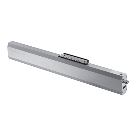
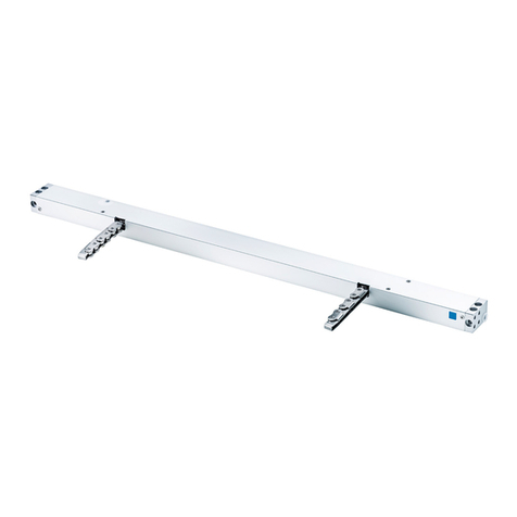
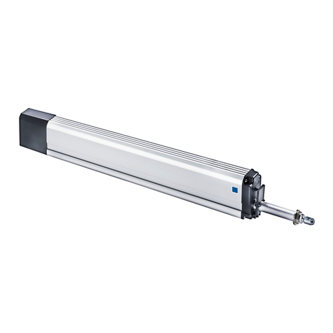
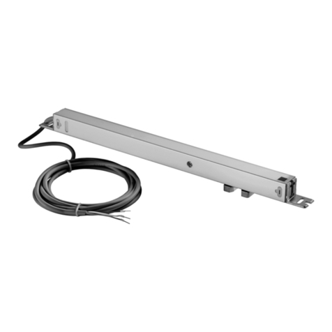
Aumuller KS 2 Training manual

KS 2 / KS 2 TWIN - CHAIN DRIVE
according to Machinery Directive 2006 / 42 / EC (annex VI)
Assembly and Commissioning
Instructions

Assembly Instruction
KS2 / KS2 TWIN
CONTENTS
08
07
06
05
04
03
02
01
Abbreviations
Risk Assessment
Warning and Safety Symbols
Safety Instructions
Explanations on the product label
Data sheet KS2 S2 24V DC R/L / KS2 S2 230V AC R/L
Data sheet KS2 S12 24V DC R / KS2 S12 24V DC L
Data sheet KS2 S12 230V AC R / KS2 S12 230V AC L
Data sheet KS2 TWIN S12 24V DC
Data sheet KS2 S12 230V AC TANDEM-SET
Intended Use
Drive positioning: Symmetrical or asymmetrical
Survey: Growing variants and minimum casement heights
Possible multi-drive operating
INSTALLATION STEP 1: Pre-assembly Checks
INSTALLATION STEP 2: Prerequisites for Assembly / Preparing assembly
INSTALLATION STEP 3: Determine the casement brackets
INSTALLATION STEP 4: Determine the frame brackets (Application examples)
INSTALLATION STEP 5: Hole layout for frame bracket and casement bracket
INSTALLATION STEP 6: Assembly casement bracket
INSTALLATION STEP 7: Assembly frame bracket
INSTALLATION STEP 8: Concealing the drive
INSTALLATION STEP 9: Electric Connection
Instructions on Connection
Checking Safety and Performing Test Run
Troubleshooting, Service and Repair
Maintenance and Modifi cation
Removal and Disposal
Target Groups
Warranty and After-Sales Service
Liability
Certifi cates
Survey: Growing variants and minimum casement heights
3-5
6 - 21
22 - 24
25 - 26
27 - 57
58 - 62
63 - 67
68 - 72

Assembly Instruction
KS2 / KS2 TWIN
Index of abbreviations
These abbreviations are used consistently throughout these assembly
& operating instructions. Unless stated differently, all dimensions indi-
cated in this document are in mm. General tolerances in accordance
with DIN ISO 2768-m.
A drive
AK connection cable / drive cable
AP cover cap
BD hinge
Fxxx casement bracket
FAB overall width of casement
FAH overall height of casement
FG casement weight
FL casement
FÜ casement overlap
HSK main closing edge
Kxxx frame bracket
L construction lenghth of drive
MB central hinge
NSK side closing edge
RA frame
RAB overall width of frame
RAH overall height of frame
SL snow load
opening direction
ABBREVIATIONS RISIK ANALYSIS
for power-operated windows and doors (machines)
according to ISO 12100
General Procedure
Before starting work, a risk analysis must be carried out to systematically
ensure compliance with the country-speci c legal regulations on occupatio-
nal safety and accident prevention regulations of the professional associa-
tions.
Once the risk assessment for power-operated windows and doors has
been carried out by the planner and laid down in the constructional re-
quirements, the installer of the power-operated windows and doors must
again carry out another risk assessment to examine whether the planning
requirements have been met. In case the protection class (see i. e. lea et
KB.01 of VFF [association windows + facade]) has not been met, further
steps to reduce risk are necessary.
Extract from the Machinery Directive 2006/42/EC
„The manufacturer of machinery or his authorized representative must
ensure that a risk assessment is carried out in order to determine the
health and safety requirements which apply to the machinery. The ma-
chinery must then be designed and constructed taking into account the
results of the risk assessment.“
Separate documentation relating to risk assessment can be downloaded
from the homepage of
Aumüller Aumatic GmbH (www.aumueller-gmbh.de).
In addition, the operator needs to be instructed about the residual risks.
It is essential to ensure compliance with the latest version of the guide-
lines, standards and national legislation applicable to the assembly and
the electrical connection of drives / controls, especially:
EN 60335-1 / EN 60335-2-103
„Household and similar electrical appliances - Safety - Part 1: General
requirements / - Part 2-103: Particular requirements for drives for gates,
doors and windows“
Directive 2006/24/EC of the European Parliament and of the
Council - „Machinery Directive“
Local accident prevention regulations.
Fire behaviour of building materials and building components.
Erection of power installations with rated voltages below 1000V
Failure to comply with the warning notes results
in irreversible injuries or death.
Failure to comply with the warning notes can
result in irreversible injuries or death.
Failure to comply with the warning notes can
result in minor or moderate (reversible) injuries.
Failure to comply with the warning notes can
lead to damage to property.
WARNING AND SAFETY SYMBOLS IN THESE INSTRUCTIONS:
The symbols used in the instructions shall be strictly observed and have the following meaning:
Caution / Warning
Danger due to electric current.
Caution / Warning
Risk of crushing and entrapment during device operati-
on (is provided as a sticker with the drive).
Attention / Warning
Risk of damage to / destruction of drives and / or win-
dows.
WARNING
DANGER
CAUTION
NOTE
01
ABBREVIATIONS; RISIK ASSEMBLY
WARNING AND SAFETY SYMBOLS IN THESE INSTRUCTIONS

Assembly Instruction
KS2 / KS2 TWIN
01
SAFETY INSTRUCTIONS
Danger spots by crush and shear points
Side-hung Bottom-hung Roof windows / skyskylight domes Louvre windows
Danger spots: crush and shear points
SAFETY INSTRUCTIONS
Important safety instructions: To ensu-
re safety of persons, these instructions
must be strictly observed.
Always keep these instructions available.
Risk of crushing and entrapment!
Window closes automatically!
When closing or opening the drive is stopped
by the drive-integrated or external electronic
load disconnection.
There is always enough pressure force to
crush ngers in case of carelessness.
Do not put your hand into the window rabbet or into the
moving chain during assembly work and operation !
Make sure that entrapment between the moving casement
and the x elements (i. e. wall), due to openings, is not pos-
sible.
Crush and shear points
Crush and shear points between casements and frames
must be secured up to a height of 2.5 m (bottom edge of
moving element) by devices that will stop the movement
by touch or interruption initiated by a person and prevent
any injury. A warning sign must be clearly attached to the
opening element.
On power-operated doors and gates danger spots of crush
and shear points must be secured against entrapment by
appropriate measures to prevent injuries.
Casements must be hung or secured such way that, in case
one of the mounting elements fails, it will not break away /
slam down or move in an uncontrolled manner by providing
double suspensions, safety scissors, casement stays.
Bottom-hung windows must be provided with safety scis-
sors or similar devices. Safety stays prevent damage and
injuries to persons which might result from improper instal-
lation and handling.
The safety scissors must match the opening stroke of the
drive (see technical data). This means: the opening width of
the safety scissors must be greater than the drive stroke in
order to avoid any blocking.
Mounting, Operation and Maintenance Instructions
These instructions shall allow professional assembly, com-
missioning and maintenance carried out by quali ed and
safety-minded electricians and/or skilled staff with in-depth
knowledge of electrical and mechanical drive assembly.
To ensure safe operation and avoid damage and risks the
system must be carefully assembled and adjusted according
to these assembly instructions. All dimensions have to be
veri ed at the place of installation and must be adjusted,
if required.
Please note the connection assignment, the
permissible drive voltage (see type plate), the
minimum and maximum performance data
(see technical data) and the assembly and in-
stallation notes and strictly adhere to them!
Never connect 24 V DC drives to 230 V supply!
Danger to life !
safety scissors
WARNING
Secure the window in front of inadvertent or
unintentional opening and against falling.

Assembly Instruction
KS2 / KS2 TWIN
01
SAFETY INSTRUCTIONS
Cable routing and electrical connection
Cable routing and electrical connections may only be car-
ried out by approved contractors. Secure power supply lines
230 / 400V AC separately on site. Before working on the
system the mains voltage supply and the emergency power
supply (i. e. batteries) shall be disconnected in all poles and
secured against unintended operation.
Never operate the drives, controllers, manual switches and
sensors on operating voltages and connections contrary to
the speci cations in the operating instructions.
All relevant regulations must be observed for the installa-
tion:
Erection of power installations with rated voltages below
1000 V
Installation of cables and lines
Fire behaviour of building materials and building compo-
nents
Specify suitable types of cable on consultation with the
competent local authorities, energy supply companies and
Employers’ Liability Insurance Associations. Please pay
especially regard to: All extra low-voltage lines (24 V DC)
must be laid separately from power cables. Flexible lines
must not be ush-mounted. Freely suspended lines must be
provided with strain relief.
All lines must be laid such way that they can
be neither sheared off, nor twisted or kinked
during operation.
All junction boxes and external drive controllers must be
positioned to allow access for maintenance work. The cable
type, lengths and sizes must comply with the technical
speci cations. Check connection points for tight t of the
screwed connections and cable ends.
All 230 V components shall allow disconnec-
tion in all poles from the mains power supply
prior to maintenance and repair work.
After mounting
and each modi cation to the structure, check all functions
in a test run. Once the system is completely installed, the
end-user must be instructed on all important operating
steps. The end-user must also be noti ed of the remaining
risks / hazards.
Ambient Conditions
The product must not be hit, dropped or exposed to vibra-
tions, moisture, aggressive gases or other damaging envi-
ronments unless it is approved for one or several of these
ambient conditions by the manufacturer.
Accident prevention regulations and guidelines is-
sued by the employers’ liability insurance association
When working at, in or on a building or part of a building
the speci cations and notes of the respective accident pre-
vention regulations (UVV) and the regulations and rules of
the employers’ liability insurance association (BGR) must be
observed and adhered to.
Declaration of Incorporation
The devices are manufactured and tested in accordance
with the European Directives. The appropriate declaration
of incorporation has been issued. You may only operate the
drive if there is a declaration of conformity within the mea-
ning of the Machinery Directive for the entire system.
Spare parts, fasteners, ttings and controllers
Only operate the drive with controllers built by the same
manufacturer. There is no liability, warranty or customer
service if third-party parts are used. If spare parts/ ttings
or extension parts are required, only original replacement
parts from the manufacturer may be used.
Range of Application
Exclusively suited for the automatic opening and closing of
the window types speci ed in these assembly instructions.
For any application not included in these instructions plea-
se consult the manufacturer or his authorized reseller for
further information.
Do not misuse device for any other lifting
operations.
Always check that your system complies with the applicable
regulations. Special attention shall be given to opening
width and opening area of the window, permissible t-
ting dimensions, opening time and opening speed, exerted
forces, temperature resistance of drive/devices and cables
as well as to the cross-section of the connection cable de-
pending on the cable length and the power consumption.
Required fastening material shall be selected and, if
necessary, completed to suit the drive and the exerted loads.
Make sure that all products installed are per-
manently protected from dirt and moisture
unless the drive is expressly suited for use in
damp or humid environments (see technical
data).
Mounting and fastening material
Required or supplied fastening material shall be selected
and, if necessary, supplemented to suit the building’s struc-
ture and the corresponding strain.

Assembly Instruction
KS2 / KS2 TWIN
DATA SHEET KS2 S2 24V DC R/L
DATA SHEET KS2 S2 24V DC R/L
02
Application: Natural ventilation as single-drive
Internal load dependend cut-off switch S2 in OPEN / CLOSE direction
TECHNICAL DATA
UNRated voltage 24V DC (± 20 %), max. 2 Vpp
INRated current 0,5 A
IACut-off current 0,7 A
PNRated power 12 W
ED Duty cycle 30 % (ON: 3 min. / OFF: 7 min.)
Protection rating IP 32
Ambient temperature range -5 °C ... +75 °C
FZPulling force max. 200 N
FAPushing force 500150100200500400600300200ZugPullSchubPushs (mm)
F
(N)
800s > 600 mm only for pulling application
FHPullout force 1.800 N (fastening depended)
Chain Stainless steel
Connecting cable Non-halogen, grey 2 x 0,75 mm², ~ 3 m
v Speed 10,0 mm/s 10,0 mm/s
s Stroke 200 – 800 mm (± 5 %)
L Length see order data
OPTIONS
Special model PU / pcs. Part.-No.
Drive housing painted/powder coated in other RAL colours
Specify at order stage:
1 – 4 516004
5 – 9 516004
10 – 49 516004
50 – 99 516004
up 100 516004
Extra length connecting cable:
5 m – non-halogen, grey – 2 x 0,75 mm² 501024
10 m – non-halogen, grey – 2 x 0,75 mm² 501026
24V
(Right)
(Left)

Assembly Instruction
KS2 / KS2 TWIN
DATA SHEET KS2 S2 24V DC R/L
EXPLANATIONS ON THE PRODUCT LABEL
02
Order Data
s [mm] L [mm] Version Finish PU / pcs. Part.-No.
200 335
KS2 200 S2 24V R (Right) E6/C-0 1 521120
RAL 9016 1 1001521120
KS2 200 S2 24V L (Left) E6/C-0 1 521420
RAL 9016 1 1001521420
300 380
KS2 300 S2 24V R (Right) E6/C-0 1 521130
RAL 9016 1 1001521130
KS2 300 S2 24V L (Left) E6/C-0 1 521430
RAL 9016 1 1001521430
400 430
KS2 400 S2 24V R (Right) E6/C-0 1 521140
RAL 9016 1 1001521140
KS2 400 S2 24V L (Left) E6/C-0 1 521440
RAL 9016 1 1001521440
500 545
KS2 500 S2 24V R (Right) E6/C-0 1 521150
RAL 9016 1 1001521150
KS2 500 S2 24V L (Left) E6/C-0 1 521450
RAL 9016 1 1001521450
600 545
KS2 600 S2 24V R (Right) E6/C-0 1 521160
RAL 9016 1 1001521160
KS2 600 S2 24V L (Left) E6/C-0 1 521460
RAL 9016 1 1001521460
800 625
KS2 800 S2 24V R (Right) E6/C-0 1 521180
RAL 9016 1 1001521180
KS2 800 S2 24V L (Left) E6/C-0 1 521480
RAL 9016 1 1001521480
KS2 400 S2 24V R
Made in Germany
Date: 14W36 V2.0
SN: 33942410002
Part.-No.: 521140
s: 400 mm
U: 24V DC
IA: 0,7 A
F: 200 N
ED: 30%
IP: 32
D-86672 Thierhaupten
Tel. 08271 / 8185-0 +75°C
-5°C
Version:
Right
load dependend
cut-off switch
24V
NOTE
The product label provides information on the most import-
ant caracteristics, such as:
• manufacturer‘s address
• article reference number and name
• technical caracteristics
• date of manufacturing with rmware version
• serial number
Never install and operate damaged
products.
In the event of any complaints, please indicate the
product serial number (SN) (see product label).
serial numberDuty cycle
ON: 3 minutes
OFF: 7 minutes article reference
number
date of manufacturing
with rmware version
EXPLANATIONS ON THE PRODUCT LABEL
stroke

Assembly Instruction
KS2 / KS2 TWIN
DATA SHEET KS2 S2 230V AC R/L
DATA SHEET KS2 S2 230V AC R/L
02
Application: Natural ventilation as single-drive
Internal load dependend cut-off switch S2 in OPEN / CLOSE direction
Parallel connection up to 8 drives in one group
TECHNICAL DATA
UNRated voltage 230V AC (50 Hz)
INRated current 0,13 A
IACut-off current 0,2 A
PNRated power 30 W
ED Duty cycle 30 % (ON: 3 min. / OFF: 7 min.)
Protection rating IP 32
Ambient temperature range -5 °C ... +60 °C
FZPulling force max. 200 N
FAPushing force
s > 600 mm only for pulling application
FHPullout force 1.800 N (fastening depended)
Chain Stainless steel
Connecting cable Non-halogen, grey 6 x 0,75 mm², ~ 3 m
v Speed 10,0 mm/s 10,0 mm/s
s Stroke 200 – 800 mm (± 5 %)
L Length see order data
500150100200500400600300200ZugPullSchubPushs (mm)
F
(N)
800230V
(Right)
(Left)

Assembly Instruction
KS2 / KS2 TWIN
DATA SHEET KS2 S2 230V AC R / L
02
Order Data
s [mm] L [mm] Version Finish PU / pcs. Part.-No.
200 475
KS2 200 S2 230V R (Right) E6/C-0 1 494920
RAL 9016 1 1001494920
KS2 200 S2 230V L (Left) E6/C-0 1 494720
RAL 9016 1 1001494720
300 520
KS2 300 S2 230V R E6/C-0 1 494930
RAL 9016 1 1001494930
KS2 300 S2 230V L E6/C-0 1 494730
RAL 9016 1 1001494730
400 570
KS2 400 S2 230V R E6/C-0 1 494940
RAL 9016 1 1001494940
KS2 400 S2 230V L E6/C-0 1 494740
RAL 9016 1 1001494740
500 685
KS2 500 S2 230V R E6/C-0 1 494950
RAL 9016 1 1001494950
KS2 500 S2 230V L E6/C-0 1 494750
RAL 9016 1 1001494750
600 685
KS2 600 S2 230V R E6/C-0 1 494960
RAL 9016 1 1001494960
KS2 600 S2 230V L E6/C-0 1 494760
RAL 9016 1 1001494760
800 765
KS2 800 S2 230V R E6/C-0 1 494980
RAL 9016 1 1001494980
KS2 800 S2 230V L E6/C-0 1 494780
RAL 9016 1 1001494780
OPTIONS
Special model PU / pcs. Part.-No.
Drive housing painted/powder coated in other RAL colours
Specify at order stage:
1 – 4 516004
5 – 9 516004
10 – 49 516004
50 – 99 516004
up 100 516004
Extra length connecting cable:
5 m – non-halogen, grey – 6 x 0,75 mm² 501164
10 m – non-halogen, grey – 6 x 0,75 mm² 501166
230V

Assembly Instruction
KS2 / KS2 TWIN
DATA SHEET KS2 S12 24V DC R
DATA SHEET KS2 S12 24V DC R
02
Application: natural ventilation, SHEV, ferralux®-NSHEV
Internal intelligent cut-off switch S12
Z-Version: Programmable feedback limit position „OPEN“ and „CLOSE“ (max. 24V, 500 mA)
Programmable special functions
M-COM for automatic synchronised run of multi drive systems and automatic sequence
control with FV locking drives (S3/S12 SW V2)
TECHNICAL DATA
UNRated voltage 24V DC (± 20 %), max. 2 Vpp
INRated current 0,7 A
IACut-off current 1,0 A
PNRated power 17 W
ED Duty cycle 30 % (ON: 3 min. / OFF: 7 min.)
Protection rating IP 32
Ambient temperature range -5 °C ... +75 °C
FZPulling force max. 250 N
FAPushing force 500250150100200500400600300200s (mm)
F
(N)
800ZugPullSchubPushs > 600 mm only for pulling application
FHPullout force 1.800 N (fastening depended)
Chain Stainless steel
Connecting cable Non-halogen, grey 3 x 0,5 mm², ~ 3 m
Z-Version: 5 x 0,5 mm² ~ 3 m
v Speed s < 400 8,0 mm/s 8,0 mm/s
s 500 – 600 12,0 mm/s 8,0 mm/s
s > 600 13,5 mm/s 8,0 mm/s
s Stroke 200 – 800 mm (± 5 %)
L Length see order data
24V
(Right)

Assembly Instruction
KS2 / KS2 TWIN
DATA SHEET KS2 S12 24V DC R
02
Order Data
s [mm] L [mm] Version Finish PU / pcs. Part.-No.
200 335
KS2 200 S12 24V R (Right) E6/C-0 1 521620
RAL 9016 1 1001521620
KS2 200 S12 24V R Z E6/C-0 1 521623
RAL 9016 1 1001521623
300 380
KS2 300 S12 24V R E6/C-0 1 521630
RAL 9016 1 1001521630
KS2 300 S12 24V R Z E6/C-0 1 521633
RAL 9016 1 1001521633
400 430
KS2 400 S12 24V R E6/C-0 1 521640
RAL 9016 1 1001521640
KS2 400 S12 24V R Z E6/C-0 1 521643
RAL 9016 1 1001521643
500 545
KS2 500 S12 24V R E6/C-0 1 521650
RAL 9016 1 1001521650
KS2 500 S12 24V R Z E6/C-0 1 521653
RAL 9016 1 1001521653
600 545
KS2 600 S12 24V R E6/C-0 1 521660
RAL 9016 1 1001521660
KS2 600 S12 24V R Z E6/C-0 1 521663
RAL 9016 1 1001521663
800 625
KS2 800 S12 24V R E6/C-0 1 521680
RAL 9016 1 1001521680
KS2 800 S12 24V R Z E6/C-0 1 521683
RAL 9016 1 1001521683
OPTIONS
Special model PU / pcs. Part.-No.
Drive housing painted/powder coated in other RAL colours
Specify at order stage:
1 – 4 516004
5 – 9 516004
10 – 49 516004
50 – 99 516004
up 100 516004
Extra length connecting cable:
5 m – non-halogen, grey – 3 x 0,5 mm² 501034
10 m – non-halogen, grey – 3 x 0,5 mm² 501036
5 m – non-halogen, grey – 5 x 0,5 mm² 501054
10 m – non-halogen, grey – 5 x 0,5 mm² 501056
Microprocessor programming S12
Electronic stroke reduction 524190
Special functions 524180
Optional accessories PU / pcs. Part.-No.
M-COM Comm. module for synchronised multi-drive systems 1 524177
24V

Assembly Instruction
KS2 / KS2 TWIN
DATA SHEET KS2 S12 24V DC L
DATA SHEET KS2 S12 24V DC L
02
Application: natural ventilation, SHEV, ferralux®-NSHEV
Internal intelligent cut-off switch S12
Z-Version: Programmable feedback limit position „OPEN“ and „CLOSE“ (max. 24V, 500 mA)
Programmable special functions
M-COM for automatic synchronised run of multi drive systems and automatic sequence
control with FV locking drives (S3/S12 SW V2)
TECHNICAL DATA
UNRated voltage 24V DC (± 20 %), max. 2 Vpp
INRated current 0,7 A
IACut-off current 1,0 A
PNRated power 17 W
ED Duty cycle 30 % (ON: 3 min. / OFF: 7 min.)
Protection rating IP 32
Ambient temperature range -5 °C ... +75 °C
FZPulling force max. 250 N
FAPushing force 500250150100200500400600300200s (mm)
F
(N)
800ZugPullSchubPushs > 600 mm only for pulling application
FHPullout force 1.800 N (fastening depended)
Chain Stainless steel (1.4310)
Connecting cable Non-halogen, grey 3 x 0,5 mm², ~ 3 m
Z-Version: 5 x 0,5 mm² ~ 3 m
v Speed s < 400 8,0 mm/s 8,0 mm/s
s 500 – 600 12,0 mm/s 8,0 mm/s
s > 600 13,5 mm/s 8,0 mm/s
s Stroke 200 – 800 mm (± 5 %)
L Length see order data
24V
(Left)

Assembly Instruction
KS2 / KS2 TWIN
DATA SHEET KS2 S12 24V DC L
02
ORDER DATA
s [mm] L [mm] Version Finish PU / pcs. Part.-No.
200 335
KS2 200 S12 24V L (Left) E6/C-0 1 521720
RAL 9016 1 1001521720
KS2 200 S12 24V L Z E6/C-0 1 521723
RAL 9016 1 1001521723
300 380
KS2 300 S12 24V L E6/C-0 1 521730
RAL 9016 1 1001521730
KS2 300 S12 24V L Z E6/C-0 1 521733
RAL 9016 1 1001521733
400 430
KS2 400 S12 24V L E6/C-0 1 521740
RAL 9016 1 1001521740
KS2 400 S12 24V L Z E6/C-0 1 521743
RAL 9016 1 1001521743
500 545
KS2 500 S12 24V L E6/C-0 1 521750
RAL 9016 1 1001521750
KS2 500 S12 24V L Z E6/C-0 1 521753
RAL 9016 1 1001521753
600 545
KS2 600 S12 24V L E6/C-0 1 521760
RAL 9016 1 1001521760
KS2 600 S12 24V L Z E6/C-0 1 521763
RAL 9016 1 1001521763
800 625
KS2 800 S12 24V L E6/C-0 1 521780
RAL 9016 1 1001521780
KS2 800 S12 24V L Z E6/C-0 1 521783
RAL 9016 1 1001521783
OPTIONS
Special model PU / pcs. Part.-No.
Drive housing painted/powder coated in other RAL colours
Specify at order stage:
1 – 4 516004
5 – 9 516004
10 – 49 516004
50 – 99 516004
up 100 516004
Extra length connecting cable:
5 m – non-halogen, grey – 3 x 0,5 mm² 501034
10 m – non-halogen, grey – 3 x 0,5 mm² 501036
5 m – non-halogen, grey – 5 x 0,5 mm² 501054
10 m – non-halogen, grey – 5 x 0,5 mm² 501056
Microprocessor programming S12
Electronic stroke reduction 524190
Special functions 524180
Optional accessories PU / pcs. Part.-No.
M-COM Comm. module for synchronised multi-drive systems 1 524177
24V

Assembly Instruction
KS2 / KS2 TWIN
DATA SHEET KS2 S12 230V AC R
DATA SHEET KS2 S12 230V AC R
02
Application: natural ventilation
Internal intelligent cut-off switch S12
Parallel connection up to 8 drives in one group
Z-Version: Programmable feedback limit position „OPEN“ and „CLOSE“
(max. 24V, 500 mA)
Programmable synchronised run (max. 4 drives) and special functions
TECHNICAL DATA
UNRated voltage 230V AC (50 Hz)
INRated current 0,13 A
IACut-off current 0,2 A
PNRated power 30 W
ED Duty cycle 30 % (ON: 3 min / OFF: 7 min.)
Protection rating IP 32
Ambient temperature range -5 °C ... +60 °C
FZPulling force max. 250 N
FAPushing force 500250150100200500400600300200s (mm)
F
(N)
800ZugPullSchubPushs > 600 mm only for pulling application
FHPullout force 1.800 N (fastening depended)
Chain Stainless steel
Connecting cable Non-halogen, grey 6 x 0,75 mm², ~ 3 m
v Speed 8,0 mm/s 8,0 mm/s
s Stroke 200 – 800 mm (± 5 %)
L Length see order data
230V
(Right)

Assembly Instruction
KS2 / KS2 TWIN
DATA SHEET KS2 S12 230V AC R
02
ORDER DATA
s [mm] L [mm] Version Finish PU / pcs. Part.-No.
200 475
KS2 200 S12 230V R (Right) E6/C-0 1 494020
RAL 9016 1 1001494020
KS2 200 S12 230V R Z E6/C-0 1 494023
RAL 9016 1 1001494023
300 520
KS2 300 S12 230V R E6/C-0 1 494030
RAL 9016 1 1001494030
KS2 300 S12 230V R Z E6/C-0 1 494033
RAL 9016 1 1001494033
400 570
KS2 400 S12 230V R E6/C-0 1 494040
RAL 9016 1 1001494040
KS2 400 S12 230V R Z E6/C-0 1 494043
RAL 9016 1 1001494043
500 685
KS2 500 S12 230V R E6/C-0 1 494050
RAL 9016 1 1001494050
KS2 500 S12 230V R Z E6/C-0 1 494053
RAL 9016 1 1001494053
600 685
KS2 600 S12 230V R E6/C-0 1 494060
RAL 9016 1 1001494060
KS2 600 S12 230V R Z E6/C-0 1 494063
RAL 9016 1 1001494063
800 765
KS2 800 S12 230V R E6/C-0 1 494080
RAL 9016 1 1001494080
KS2 800 S12 230V R Z E6/C-0 1 494083
RAL 9016 1 1001494083
OPTIONS
Special model PU / pcs. Part.-No.
Drive housing painted/powder coated in other RAL colours
Specify at order stage:
1 – 4 516004
5 – 9 516004
10 – 49 516004
50 – 99 516004
up 100 516004
Extra length connecting cable:
5 m – non-halogen, grey – 6 x 0,75 mm² 501164
10 m – non-halogen, grey – 6 x 0,75 mm² 501166
Microprocessor programming S12
Synchronised multi-drive set functions 495588
Electronic stroke reduction 495590
Special functions 524180
230V

Assembly Instruction
KS2 / KS2 TWIN
DATA SHEET KS2 S12 230V AC L
DATA SHEET KS2 S12 230V AC L
02
Application: natural ventilation
Internal intelligent cut-off switch S12
Parallel connection up to 8 drives in one group
Z-Version: Programmable feedback limit position „OPEN“ and „CLOSE“
(max. 24V, 500 mA)
Programmable synchronised run (max. 4 drives) and special functions
TECHNICAL DATA
UNRated voltage 230V AC (50 Hz)
INRated current 0,13 A
IACut-off current 0,2 A
PNRated power 30 W
ED Duty cycle 30 % (ON: 3 min / OFF: 7 min.)
Protection rating IP 32
Ambient temperature range -5 °C ... +60 °C
FZPulling force max. 250 N
FAPushing force
500250150100200500400600300200s (mm)
F
(N)
800ZugPullSchubPushs > 600 mm only for pulling application
FHPullout force 1.800 N (fastening depended)
Chain Stainless steel (1.4310)
Connecting cable Non-halogen, grey 6 x 0,75 mm², ~ 3 m
v Speed 8,0 mm/s 8,0 mm/s
s Stroke 200 – 800 mm (± 5 %)
L Length see order data
230V
(Left)

Assembly Instruction
KS2 / KS2 TWIN
DATA SHEET KS2 S12 230V AC L
02
OPTIONS
Special model PU / pcs. Part.-No.
Drive housing painted/powder coated in other RAL colours
Specify at order stage:
1 – 4 516004
5 – 9 516004
10 – 49 516004
50 – 99 516004
up 100 516004
Extra length connecting cable:
5 m – non-halogen, grey – 6 x 0,75 mm² 501164
10 m – non-halogen, grey – 6 x 0,75 mm² 501166
Microprocessor programming S12
Synchronised multi-drive set functions 495588
Electronic stroke reduction 495590
Special functions 524180
ORDER DATA
s [mm] L [mm] Version Finish PU / pcs. Part.-No.
200 475
KS2 200 S12 230V L (Left) E6/C-0 1 494120
RAL 9016 1 1001494120
KS2 200 S12 230V L Z E6/C-0 1 494123
RAL 9016 1 1001494123
300 520
KS2 300 S12 230V L E6/C-0 1 494130
RAL 9016 1 1001494130
KS2 300 S12 230V L Z E6/C-0 1 494133
RAL 9016 1 1001494133
400 570
KS2 400 S12 230V L E6/C-0 1 494140
RAL 9016 1 1001494140
KS2 400 S12 230V L Z E6/C-0 1 494143
RAL 9016 1 1001494143
500 685
KS2 500 S12 230V L E6/C-0 1 494150
RAL 9016 1 1001494150
KS2 500 S12 230V L Z E6/C-0 1 494153
RAL 9016 1 1001494153
600 685
KS2 600 S12 230V L E6/C-0 1 494160
RAL 9016 1 1001494160
KS2 600 S12 230V L Z E6/C-0 1 494163
RAL 9016 1 1001494163
800 765
KS2 800 S12 230V L E6/C-0 1 494180
RAL 9016 1 1001494180
KS2 800 S12 230V L Z E6/C-0 1 494183
RAL 9016 1 1001494183
230V

Assembly Instruction
KS2 / KS2 TWIN
DATA SHEET KS2 TWIN S12 24V DC
DATA SHEET KS2 TWIN S12 24V DC
02
Application: natural ventilation, RWA
Internal intelligent cut-off switch S12
Z-Version: Programmable feedback limit position „OPEN“ and „CLOSE“ (max. 24V, 500 mA)
Programmable special functions
M-COM for automatic synchronised run of multi drive systems and automatic sequence
control with FV locking drives (S3/S12 SW V2)
TECHNICAL DATA
U
N
Rated voltage 24V DC (± 20 %), max. 2 Vpp
I
N
Rated current 1,4 A
I
A
Cut-off current 2,0 A
P
N
Rated power 34 W
ED Duty cycle 30 % (ON: 3 min / OFF: 7 min.)
Protection rating IP 32
Ambient temperature range -5 °C ... +75 °C
F
Z
Pulling force max. 500 N
F
A
Pushing force
1000500300200400500400600300200s (mm)
F
(N)
ZugPullSchubPush
F
H
Pullout force 1.800 N (fastening depended)
Chain Stainless steel
Connecting cable Non-halogen, grey 3 x 0,5 mm², ~ 3 m
Z-Version: 5 x 0,5 mm² ~ 3 m
v Speed s < 400 8,0 mm/s 8,0 mm/s
s 500 – 600 12,0 mm/s 8,0 mm/s
s Stroke 200 – 600 mm (± 5 %)
L Length see order data
LM Distance in between chains see order data
24V

Assembly Instruction
KS2 / KS2 TWIN
DATA SHEET KS2 TWIN S12 24V DC
02
Order Data
s [mm] L [mm] LM [mm] Version Finish PU / pcs. Part.-No.
200 640 350 KS2 TWIN 200 S12 24V E6/C-0 1 521820
KS2 TWIN 200 S12 24V Z E6/C-0 1 521823
400 830 540 KS2 TWIN 400 S12 24V E6/C-0 1 521840
KS2 TWIN 400 S12 24V Z E6/C-0 1 521843
500 1060 770 KS2 TWIN 500 S12 24V E6/C-0 1 521850
KS2 TWIN 500 S12 24V Z E6/C-0 1 521853
600 1060 770 KS2 TWIN 600 S12 24V E6/C-0 1 521860
KS2 TWIN 600 S12 24V Z E6/C-0 1 521863
OPTIONS
Special model PU / pcs. Part.-No.
Drive housing painted/powder coated in other RAL colours
Specify at order stage:
1 – 4 516004
5 – 9 516004
10 – 49 516004
50 – 99 516004
up 100 516004
Extra length connecting cable:
5 m – non-halogen, grey – 3 x 0,5 mm² 501034
10 m – non-halogen, grey – grau 3 x 0,5 mm² 501036
5 m – non-halogen, grey – 5 x 0,5 mm² 501054
10 m – non-halogen, grey – 5 x 0,5 mm² 501056
Microprocessor programming S12
Elektronische Strokeverkürzung ( Antriebe 24V DC) 524190
Special functions 524180
Optional accessories PU / pcs. Part.-No.
M-COM Comm. module for synchronised multi-drive systems 1 524177
24V

Assembly Instruction
KS2 / KS2 TWIN
DATA SHEET KS2 S12 230V AC TANDEM-SET
DATA SHEET KS2 S12 230V AC TANDEM-SET
02
TECHNICAL DATA
U
N
Rated voltage 230V AC (50 Hz)
I
N
Rated current 0,15 A
I
A
Cut-off current 0,2 A
P
N
Rated power 35 W
ED Duty cycle 30 % (ON: 3 min. / OFF: 7 min.)
Protection rating IP 32
Ambient temperature range -5 °C ... +60 °C
F
Z
Pulling force max. 2 x 250 N
F
A
Pushing force
1000500300200400500400600300200s (mm)
F
(N)
ZugPullSchubPush
s > 600 mm only for pulling application
F
H
Pullout force 1.800 N (fastening depended)
Chain Stainless steel
Connecting cable Master: Non-halogen, grey
Slave: Non-halogen, grey
6 x 0,75 mm², ~ 3 m
3 x 0,5 mm², ~ 3 m
3 x 0,5 mm², ~ 3 m
v Speed 8,0 mm/s 8,0 mm/s
s Stroke 200 – 800 mm (± 5 %)
L Length see order data
Application: natural ventilation
Factory-confi gured set includes:
Master: KS2 S12 230V AC R / L with voltage output 24V DC
Slave: KS2 S12 24V DC R / L with conection cable on the motor side
KS2 S12 24V DC L-K with conection cable on the chain side
Sequence control with FV locking drives (S3/S12 SW V2)
Parallel connection up to 8 sets of drives in one group
Junction box to be site supplied
Programmable special functions and sequence control with FV locking drives (S3/S12 SW V2)
Screw terminal connections in drive housing upon request
230V
This manual suits for next models
1
Table of contents
Other Aumuller DC Drive manuals
Aumuller
Aumuller KS 15 800 S12 Training manual
Aumuller
Aumuller KS4 S12 24V DC R Training manual
Aumuller
Aumuller KS4 S12 24V DC R Training manual
Aumuller
Aumuller PLS15 S12 24V DC Series Training manual
Aumuller
Aumuller FV1 Training manual
Aumuller
Aumuller FVM2 Training manual
Aumuller
Aumuller LKS S2 24V DC Training manual
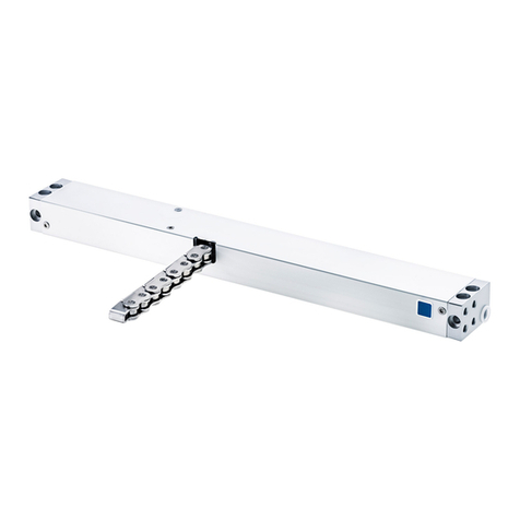
Aumuller
Aumuller KS2 S2 24V DC R/L Training manual
Aumuller
Aumuller PLS S12 24V DC Training manual
Aumuller
Aumuller ferralux KSA Series User manual
