manuals.online logo
Brands
  1. Home
  2. •
  3. Brands
  4. •
  5. Thitronik
  6. •
  7. Car Alarm
  8. •
  9. Thitronik WiPro III + safe.lock User manual

Thitronik WiPro III + safe.lock User manual

1
Disclaimer:
This installation manual is intended for
professional service companies. Appropri-
ate background knowledge about work on
vehicle electrics and electronics is there-
fore required.
Improper interventions into the vehicle
electronics and their components can un-
der certain circumstances cause them to
no longer function as intended. This can
considerably endanger the installer (work,
e.g., on the airbag system) and the road-
worthiness of the vehicle and can result
not only in property damage, but also in
personal injury.
Therefore, have all work on the vehicle
electronics carried out by a qualified shop.
Thitronik GmbH is not liable for damage to
property and/or personal injury resulting
from improper, incorrect or only partially
completed installation work. The installing
service company is obligated to ensure
that its connection work neither is faulty
in itself nor can lead to faults or dangers
on the vehicle.
The instructions in the WiPro installation
manual remain applicable. Unused inputs
and outputs must be isolated.
Should the given vehicle conditions differ
from those described herein, please con-
tact the manufacturer or our technical
support team.
Updated 12/20
WiPro III + safe.lock Installation Manual
Fiat Ducato X250
Euro 4 (2006–2011)
WiPro III + safe.lock Installation Manual – Fiat Ducato X250, Euro 4
2
Aids/tools/material:
• Ducato assembly kit
• Combination pliers
• Phillips screwdriver
• 10mm box spanner
• 3mm Allen key
• Cordless screwdriver with 8mm drill bit
for status LED
Teach-in of wireless magnetic contacts
and other transmitters
(before installation!)
1. Press the button to the right of the
connector and hold it down until the
system beeps. The status LED is con-
tinuously lit.
2. Now activate each contact and gas
alarm or radio cable loop to be stored
several (2–3) times. Successful storing
is acknowledged through a beep and
the LED goes out briefly.
Setting the CAN bus interface for vehicle
type Ducato:
1. Remove the power supply and open the
housing.
2. On the 8-way DIP switch on the circuit
board, set switch 2 and 6 to the ‘on’
position.
1
↑
on
42 5 73 6 8
3. Close the housing again and continue
with the installation.
Step 1: Remove the dashboard panelling
Remove the three Phillips-head screws as shown in the following photos.
Undo the second screw next to the steering
wheel on the left.
Remove the panel.
Undo the screws next to the steering wheel on the left and right.
1
3
2
4
WiPro III + safe.lock Installation Manual – Fiat Ducato X250, Euro 4
3
Step 2: Make preparations for connection of power supply and remove on-board computer
Step 3: Connect safe.lock wire
Connect the control lines for the central lock-
ing system as follows:
Remove the blue connector on the front side
of the on-board computer (fold the red bracket
forwards to release).
Pin 46 (connector is numbered at the bottom)
is protected via fuse 39 with 10 A (lower row,
3rd fuse from the left).
Only insert the power supply wire into pin 46
after all assembly/connection work has been
completed.
If pin 46 is already occupied (e.g. red/yellow or
red/black), the connection can be made with a
branch connector.
Remove the black plug insert (side plastic lugs
serve towards locking).
Remove three screws and pull the on-board
computer forwards to get to the connectors on
the rear side.
1
3
2
4
Pin Cable colour on vehicle Cable colour on WiPro III
safe.lock Function
28 blue/yellow → blue/black front doors
50 pink/violet → blue rear doors
WiPro III + safe.lock Installation Manual – Fiat Ducato X250, Euro 4
4
Step 4: Make CAN connection and turn signal actuation connection
Remove the blue connector on the rear side of
the on-board computer (middle).
Insert the plug inserts again; install connector.
Remove the plug inserts to access the wires.
Make connections according to the table below
with the blue gel-filled branch connectors.
Place red bracket horizontally and insert con-
nector again. The connector is secured when
the red bracket is vertical.
Pinout
and wire colour for Fiat Cable colour on WiPro Function
White insert pin 34, pink/red → pink/red flashing warning lights
Green insert pin 5, pink/white → violet/orange CAN low
Green insert pin 6, pink/black → white/orange CAN high
or CAN from other insert
Black insert pin 25, pink/white → violet/orange CAN low
Black insert pin 24, pink/black → white/orange CAN high
Note
:
Starting in
model year 2010,
pink/black has
increasingly been
replaced by violet/
black in the Fiat.
CAN low and high must be tapped from the same plug insert!
WiPro III + safe.lock Installation Manual – Fiat Ducato X250, Euro 4
5
Step 5: Make connection for horn actua-
tion
• Remove steering column cover panel (four
screws, 3mm Allen key).
• Make wiring harness under the steering
wheel accessible.
• Connect brown/green wire (pin 8) to the pink
wire on the WiPro (use blue, gel-filled branch
connector).
Step 6: Make connection to ignition
Remove the green plug on the rear side of the
on-board computer and connect the yellow
wire on the WiPro with the white/black wire
of the connector (use blue gel-filled branch
connector).
Step 7: Install status LED
Drill an 8mm hole for the LED and insert the
LED. Connect the red/black wire of the LED
with a white connector to the counterpart on
the WiPro cable set.
Note
:
A possible deviating wire colour is
green; from model year 2010 the horn wire
may possibly be green/brown.
WiPro III + safe.lock Installation Manual – Fiat Ducato X250, Euro 4
6
Step 8: Fix mounting plate
Fix the mounting plate to the earthing point on the left behind the on-board computer.
Screw the screw in tightly.
Insert the power supply wire into pin 46, insert
the plug inserts again and install the connector
again.
The connector is secured when the red lever
snaps into vertical position.
Install the on-board computer again.
WiPro III + safe.lock Installation Manual – Fiat Ducato X250, Euro 4
7
Step 9: Carry out a function test
1. The ‘lock’ button on the original vehicle
remote control arms the system.
After installation it may be necessary
to lock and unlock several times until
the system responds as the CAN bus
data first has to be synchronised.
The central control unit acknowledg-
es the activation through a beep and
flashing of the direction indicators. The
status LED flashes.
If a door in the driver’s cab is open, the
vehicle is not locked (on-board func-
tion) and the system is not activated.
2. Trigger the alarm by mechanically
opening the door on the driver’s side –
from the inside with the door handle or
from the outside by unlocking with the
mechanical key and opening the door.
3. The acoustic alarm sounds for approx.
30 seconds. The visual alarm lasts ap-
prox. 180 seconds.
4. The ‘unlock’ button disarms the system
or interrupts the alarm.
Signals during arming
If a series of short beeps is emitted during
locking, one of the taught-in magnetic
contacts is open. However, the system is
armed anyway.
Possible faults
Error
:
The system does not respond to the com-
mands from the wireless key, but emits a
beep when the power supply is applied.
Solution
:
1. Check the CAN connection (white/or-
ange and violet/orange).
2. Briefly press the button on the circuit
board to activate the diagnostics mode.
If the wireless key is being operated or
a different operation is generating data
traffic on the CAN bus, this is indicated
through flickering of the green LED (left
LED). If no data traffic is indicated, the
bus is inactive or the connection has not
been executed correctly.
Error
:
The system does not respond to the
commands from the wireless key and does
not emit a beep when the power supply is
applied.
Solution
:
1. Check the power supply.
2. Is the correct pin on the front connec-
tor occupied?
3. Crimp connection executed correctly?
4. Ignition switched on? The system is
deactivated when the ignition is active.
5. Fuse F39 present and intact?
Error
:
Although all contacts are closed, an open
contact is signalled during arming.
Solution
:
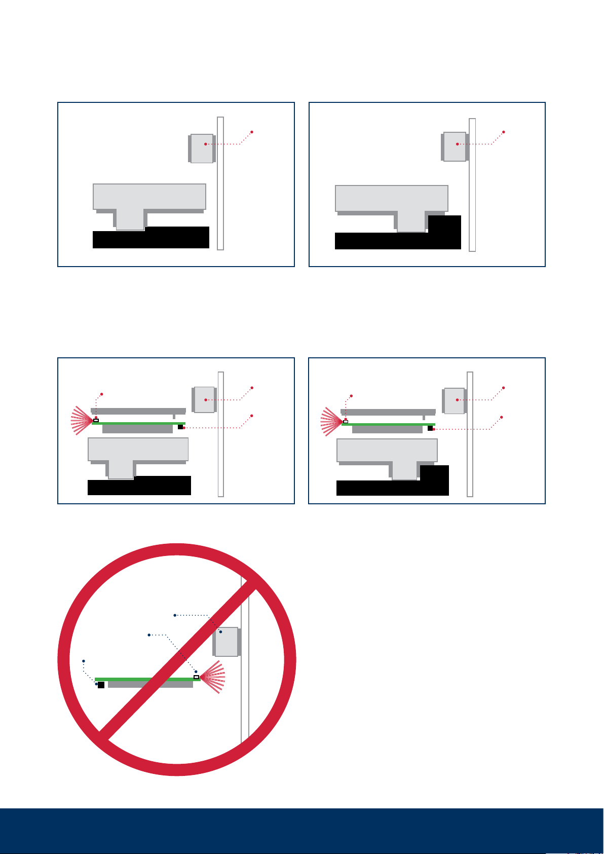
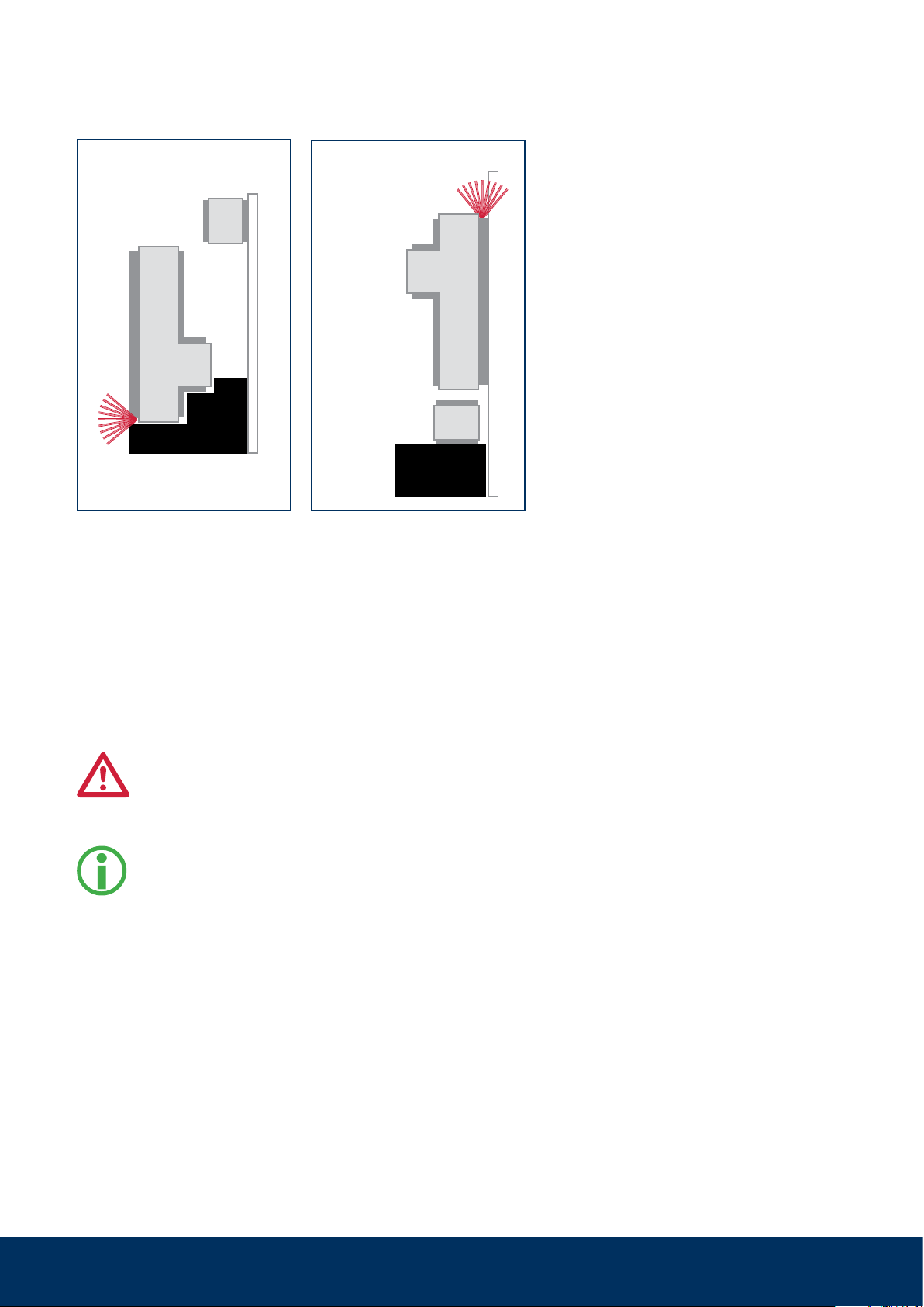
1. Check the distance between the trans-
mitter and the magnet.
2. Open and close all contacts several
times and then arm again.
3. Open contact is still being signalled >
pull out the connector for the power
supply or remove F39 (with closed con-
tacts) > reconnect the power supply.
8
Mounting of wireless magnetic contacts
868 to windows, doors, hatches etc.
Item no.: 100757, 100758
8
9
2. The circuit board is inserted into the transmitter housing (transmitter LED oriented upwards pointing away from
magnet) and the transmitter cover is snapped on.
The circuit board must not be
aligned with the transmitter LED
pointing towards the magnet!
If it is, then teach-in, but no alarm, will be possible.
Reed switch
Transmitter
LED
Magnet
1. The orientation of the transmitter housing on the window frame depends on the available space (frame profile,
distance to the roller blind or window).
Variant lying
left
Window frame
Windowpane
Transmitter housing
Magnet Magnet
Window frame
Windowpane
Transmitter housing
Variant lying
right
Magnet
Window frame
Transmitter LED
Windowpane
Transmitter housing
Reed
switch
Battery Battery
Variant lying left
Magnet
Window frame
Windowpane
Transmitter LED
Transmitter housing
Reed
switch
Variant lying right
Mounting of wireless magnetic contacts 868 to windows, doors, hatches etc.
10
Variant upright
Windowpane
Windowpane
Variant windowpane
Should upright mounting on the window
frame or mounting on the windowpane
be necessary, e.g., for space reasons,
the transmitter LED must also be aligned
pointing away from the magnet.
Alternative mounting variants
Door or hatch mounting
Ideally, the transmitter housing is aligned and
fixed on the frame and the magnet is attached
to the door leaf or the hatch. The specifica-
tions in the section ‘Positioning the magnet’
must be observed.
The circuit board must not be aligned
with the transmitter LED pointing to-
wards the magnet! If it is, then teach-
in, but no alarm, will be possible.
For bridging larger distances to
hatches or for optimal alignment of
the transmitter antenna, the use of
mounting adaptors (art. no. 100428,
100729) is recommended.
Fixing options
The wireless magnetic contacts are ideally
mounted with the help of the supplied adhe-
sive pads.
The mounting surface must be clean, dry and
grease-free. Please pretreat with a suitable
cleaning agent
as the wireless magnetic contacts may fall off
and thus unexpectedly trigger an alarm after
weeks or months of operation.
Do not process at temperatures below 15 °C.
The adhesive pads only reach their ultimate
strength after approx. 24 hours.
Should mounting with the adhesive pads not
be possible (e.g. to a door or hatch), screw
fixing is also possible. The corresponding
markings can be found on the inside of the
transmitter housing.
Mounting of wireless magnetic contacts 868 to windows, doors, hatches etc.
11
Transmitter
LED
Reed
switch
Transmitter housing
Transmitter cover
Battery
Battery Battery
Long housing leg
Short housing leg
Top view of
circuit board
Bottom view of
circuit board
Cross section
Battery
Magnet
22-30mm
Positioning the magnet
As long as the magnet is in the yellow area, its
magnetic field keeps the reed switch closed. If the
magnet moves from there into the blue area, the
reed switch is opened and a transmission opera-
tion is triggered (transmitter LED flashes). With an
armed alarm system, this leads to an alarm.
The magnet should not be mounted past the red
line and should later only move between the yellow
and blue areas.
The orientation of the transmitter housing (long leg /
short leg) is not important in this representation.
Alignment of circuit board in transmitter housing
(as-delivered condition) and positions of components.
Mounting of wireless magnetic contacts 868 to windows, doors, hatches etc.

This manual suits for next models

3

Other Thitronik Car Alarm manuals

Thitronik c.a.s. Operating instructions

Thitronik

Thitronik c.a.s. Operating instructions

Thitronik WiPro User manual

Thitronik

Thitronik WiPro User manual

Popular Car Alarm manuals by other brands

Soundstream Tarantula AL.2 installation guide

Soundstream

Soundstream Tarantula AL.2 installation guide

Toyota TVSS V installation instructions

Toyota

Toyota TVSS V installation instructions

Directed Electronics 555X manual

Directed Electronics

Directed Electronics 555X manual

Ultra Start 1280 series installation guide

Ultra Start

Ultra Start 1280 series installation guide

Alert 750R-LCD owner's manual

Alert

Alert 750R-LCD owner's manual

Viper 426FS owner's manual

Viper

Viper 426FS owner's manual

Audiovox Pursuit PRO-9342WOS2 owner's manual

Audiovox

Audiovox Pursuit PRO-9342WOS2 owner's manual

Audiovox 5BCR07 Programming guide

Audiovox

Audiovox 5BCR07 Programming guide

Uniden VS1600XR operating guide

Uniden

Uniden VS1600XR operating guide

Silencer Security Systems 4901 owner's manual

Silencer Security Systems

Silencer Security Systems 4901 owner's manual

Code Alarm CATX2LCD Programming guide

Code Alarm

Code Alarm CATX2LCD Programming guide

CrimeStopper Super Rage CS-2011DP Installation handbook

CrimeStopper

CrimeStopper Super Rage CS-2011DP Installation handbook

Clifford Bullet II owner's manual

Clifford

Clifford Bullet II owner's manual

Cobra 1046 installation manual

Cobra

Cobra 1046 installation manual

CrimeStopper SP-300 installation instructions

CrimeStopper

CrimeStopper SP-300 installation instructions

Audiovox AA-925 owner's manual

Audiovox

Audiovox AA-925 owner's manual

Phobos DS500 CAN U user manual

Phobos

Phobos DS500 CAN U user manual

Audiovox Pursuit PRO-9776 owner's manual

Audiovox

Audiovox Pursuit PRO-9776 owner's manual

manuals.online logo
manuals.online logoBrands
  • About & Mission
  • Contact us
  • Privacy Policy
  • Terms and Conditions

Copyright 2025 Manuals.Online. All Rights Reserved.