THOMSON Construction Master Pro Operation instructions

Sample

Sample
iii
Introduction / v
Important Notes for Owners of Previous Construction
Masters / vi
Glossary of Construction Terms / vii
PART A: SITE DEVELOPMENT 1
CHAPTER 1: Scaled Distances and Areas 3
CHAPTER 2: Excavation, Fill, and
Grade Lines 19
PART B: FOOTINGS, SLABS, AND WALLS 29
CHAPTER 3: Footings and Slabs 31
CHAPTER 4: Walls 41
PART C: FRAMING 49
CHAPTER 5: Walls 51
CHAPTER 6: Rafters 59
CHAPTER 7: Stairs 75
PART D: FINISHING 81
CHAPTER 8: Brick 83
CHAPTER 9: Roofing 87
CHAPTER 10: Drywall 91
ANSWERS TO PROBLEMS 95
CONTENTS

Sample
Copyright © 2007 by Calculated Industries, Inc.
and Thomson Delmar Learning
Construction Master® Pro Workbook and Study Guide
Placed atop framed walls, rafters support the roof of a structure. There are
many types of roof styles, such as gable, gambrel, shed, Mansard, and hip,
and several types of rafters, including those to be discussed here: common,
hip, valley, and jack rafters.
Common rafters connect the top plate of a wall with the ridge, and are
perpendicular to the ridge. Like the grade of a land area (see Chapter 2), the
incline of such rafters may be specified several different ways using the quan-
tities shown in Figure 6-1. The slope of a rafter (also called the pitch ratio) is
a decimal value that results from dividing the rise by the run, keeping both di-
mensions in feet or both dimensions in inches. Pitch of a rafter is the rise, in
inches, divided by the run, in feet, and is usually stated simply in inches. Pitch
may also be expressed as angle A in the figure, that angle between the rafter
and a horizontal line, and is given in degrees.
59
CHAPTER 6
Rafters
Warning
Material Adjustments:
The rafter length
calculations are the
point-to-point
measurements and do
not account for material
thickness.
Rafter Length (DIAG)
A
Run
Rise
Figure 6-1

Sample
60 Part C ■Framing
■EXAMPLE 6.1
A common rafter rises 5⬘-4⬙in a run of 14⬘-2⬙. Find (a) the pitch of this
rafter in inches, (b) its pitch in degrees and (c) its slope.
Solution:
KEYSTROKE DISPLAY
(a) (b) (c) Following the procedures outlined in Chapter 2, enter the given
data as shown, and solve for the pitch:
5 f 4 i r RISE 5 FEET 4 INCH
1 4 f 2 i R p PTCH 4-1/2 INCH
pPTCH 20.63°
p p SLP 0.376471
Your Construction Master Pro calculator can also provide the point-to-point
rafter length (excluding ridge adjustment or overhang) for common rafters, as
well as the angles, in degrees for making plumb (vertical) cuts, and level (hor-
izontal) cuts as shown in Figure 6-2. These angles may be used for fitting
rafter to ridge; cutting a bird’s mouth to seat a rafter on the top plate; or trim-
ming rafter tails to accept fascia and soffit boards.
■EXAMPLE 6.2
For the rafter of Example 6.1, find the rafter length, and angular values for
plumb and level cuts.
Solution:
KEYSTROKE DISPLAY
Enter the data for rise and run as before:
5 f 4 i r RISE 5 FEET 4 INCH
1 4 f 2 i R RUN 14 FEET 2 INCH
dDIAG 15 FEET 1-5/8 INCH
dPLMB 20.63°
dLEVL 69.37°
Using the capabilities built into your Construction Master Pro calcu-
lator, it is possible to determine all information related to common rafters
for any specified framing conditions. Three of the situations most fre-
quently encountered by builders are these:
1. Given the rise and run, determine the pitch and rafter length.
2. Given the pitch and rise, find the run and rafter length.
3. Given the pitch and run, calculate the rise and rafter length.
Notes
Construction Master® Pro Workbook and Study Guide
Copyright © 2007 by Calculated Industries, Inc.
and Thomson Delmar Learning
Calculator Tip
Pitch Display Order:
Order of answers
displayed varies
depending on last
format of pitch entered.
Continue pressing p
until desired format is
displayed.
Calculator Tip
Power User Tip:
Displayed pitch results
will start with the last
entered pitch format.
For example, if 7 i
pis entered, any
future pitch calculation
will begin with the pitch
in inch format, unless
calculator is reset.

Sample
Rafters ■Chapter 6 61
For each set of conditions listed above, it is a simple procedure to also find
the angles required for plumb cuts and level cuts. Examples 6.1 and 6.2
demonstrated the procedure for case (1.) above in which the rise and run of
a rafter are already known. The following examples demonstrate cases (2.)
and (3.) respectively.
■EXAMPLE 6.3
Calculate the run, length, plumb angle, and level angle for a common rafter
having the following characteristics. (a) Pitch of 5-1/2⬙, rise of 6⬘-4⬙
(b) Pitch of 30.5°, rise of 7⬘-2⬙.
Solution:
KEYSTROKE DISPLAY
(a) Enter the specified conditions as follows:
5 i 1 / 2 p PTCH 5-1/2 INCH
Notes
Copyright © 2007 by Calculated Industries, Inc.
and Thomson Delmar Learning
Construction Master® Pro Workbook and Study Guide
A
BA
A
A⫽Plumb cut angle (PLMB)
B⫽Level cut angle (LEVL)
Figure 6-2 (Not to scale)

Sample
62 Part C ■Framing
KEYSTROKE DISPLAY
6 f 4 i r RISE 6 FEET 4 INCH
RRUN 13 FEET 9-13/16 INCH
dDIAG 15 FEET 2-3/8 INCH
dPLMB 24.62°
dLEVL 65.38°
(b) Similarly:
3 0 • 5 p PTCH 30.50°
7 f 2 i r RISE 7 FEET 2 INCH
RRUN 12 FEET 2 INCH
dDIAG 14 FEET 1-7/16 INCH
dPLMB 30.50°
dLEVL 59.50°
■EXAMPLE 6.4
Find the rise, length, plumb angle, and level angle for a common rafter hav-
ing the following characteristics: (a) Pitch of 8⬙, run of 14⬘-6⬙(b) Pitch of
26.6°, run of 12⬘-4⬙.
Solution:
KEYSTROKE DISPLAY
(a) The solution differs only slightly from that of Example 6.3:
8 i p PTCH 8 INCH
1 4 f 6 i R RUN 14 FEET 6 INCH
rRISE 9 FEET 8 INCHES
dDIAG 17 FEET 5-1/8 INCH
dPLMB 33.69°
dLEVL 56.31°
(b) Similarly:
2 6 • 6 p PTCH 26.60°
1 2 f 4 i R RUN 12 FEET 4 INCH
rRISE 6 FEET 2-1/8 INCH
dDIAG 13 FEET 9-1/2 INCH
dPLMB 26.60°
dLEVL 63.40°
Hip rafters run diagonally upward to the roof ridge from an outside
corner formed by the top plates of two walls. These rafters represent the
lines of intersection between two different sections of roof. Valley rafters
also run diagonally upward, but from an inside corner formed by the top
Notes
Construction Master® Pro Workbook and Study Guide
Copyright © 2007 by Calculated Industries, Inc.
and Thomson Delmar Learning

Sample
Rafters ■Chapter 6 63
plates of two walls. The lines formed where two gable roofs intersect are
also framed using valley rafters. Figure 6-3 shows the plan view of an
L-shaped house, with the ridges, hip, and valley rafters marked. The rafters
shown as dashed lines are hip jack rafters (running between hip rafters and
the top of a wall plate), or valley jack rafters (running between valley
rafters and a ridge). All other rafters shown are considered to be common
rafters.
Notes
Copyright © 2007 by Calculated Industries, Inc.
and Thomson Delmar Learning
Construction Master® Pro Workbook and Study Guide
Ridge
Valley Valley Hip
Hip
Rid
g
e
Figure 6-3 (Not to scale)
Aconventional or regular roof contains common rafters having the
same pitch on both sides of the hip or valley; irregular roofs have different
pitches on either side of the hip or valley. In both cases, if the pitches joined
by a hip rafter are the same as the pitches joined by a valley rafter, then the
hip and valley rafters themselves are identical to each other in length,
plumb cut, and level cut.
One additional piece of information needed for hips and valleys is the
value of the cheek angle. This is the angle to which boards must be cut on
those surfaces which mate with the ridge/common rafters, and the corner
Warning
The roof framing
functions assume that
both ridges are
perpendicular to each
other and that the roof is
the same height
throughout.

Sample
64 Part C ■Framing
top plates. Figure 6-4(a) shows a plan view for the framing of a regular
roof, while Figure 6-4(b) shows cheek angles, A, to which the ends of the
hip rafter must be cut to ensure a smooth, tight fit. For regular roofs, the
cheek angle is 45°. All of these lengths and angles are readily available on
your Construction Master Pro calculator.
Notes
Construction Master® Pro Workbook and Study Guide
Copyright © 2007 by Calculated Industries, Inc.
and Thomson Delmar Learning
Common
(a)
(b) A
A
A
A
Common
Ridge
Ridge
Hip
45°
Figure 6-4 (Not to scale)

Sample
Rafters ■Chapter 6 65
■EXAMPLE 6.5
The common rafters on a hip roof have a pitch of 9⬙, and a run of 16⬘-4⬙.
Find the lengths, plumb cuts, and level cuts for the common rafters and hip
rafters, as well as the cheek angle for the hip rafters.
Solution:
KEYSTROKE DISPLAY
For the common rafters, use the same key sequence demonstrated in our
previous examples:
9 i p PTCH 9 INCH
1 6 f 4 i R RUN 16 FEET 4 INCH
dDIAG 20 FEET 5 INCH
dPLMB 36.87°
dLEVL 53.13°
Corresponding values for the hip rafter are obtained by successively press-
ing the Hkey:
HH/V 26 FEET 1-3/4 INCH
HPLMB 27.94°
HLEVL 62.06°
HCHK 1 45.00°
In the preceding example, notice that the plumb cut for the hip rafter
is significantly different from that of the common rafter. This phenomenon
seems to violate all rules of common sense, and is one which perplexes
many builders. (This is especially true if the common rafters are cut at an
angle of 45°!) Using our definition of pitch, however, it is fairly easy to see
why the hip rafter’s plumb cut angle is always less than the plumb cut an-
gle for its adjoining common rafters.
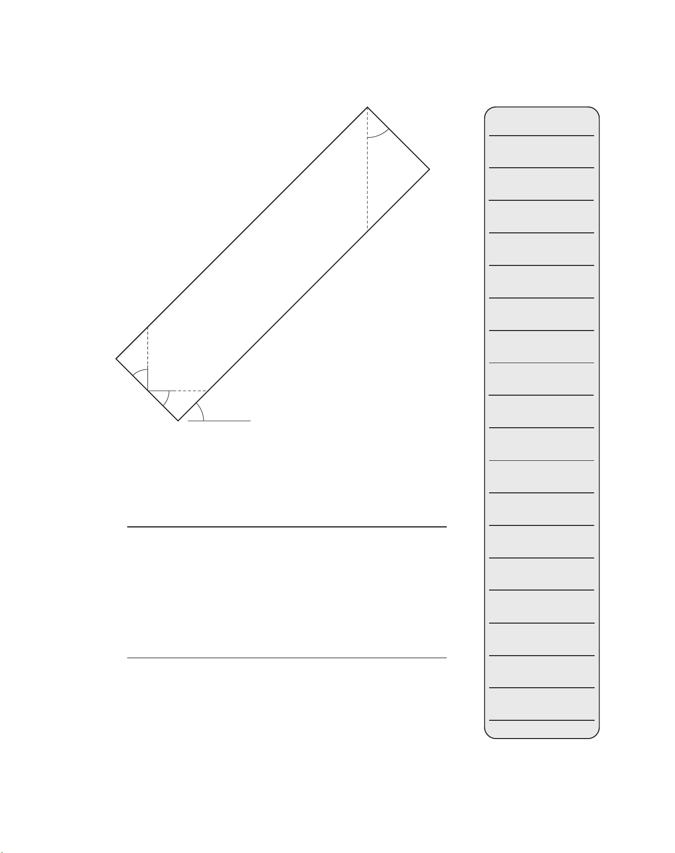
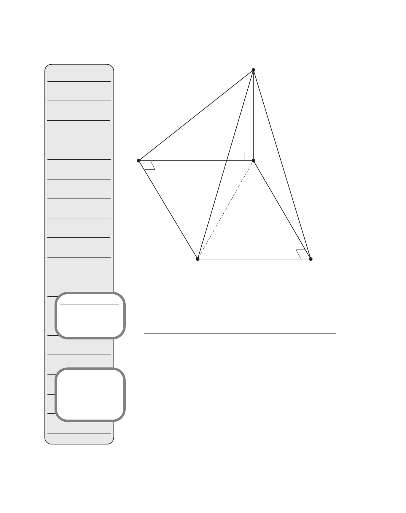
Figure 6-5 shows a typical corner for a regular roof, where the com-
mon rafters have a run of Rc and both the common and hip rafters have an
identical rise, Ri. Triangle A-B-C in the horizontal plane is a 45° right tri-
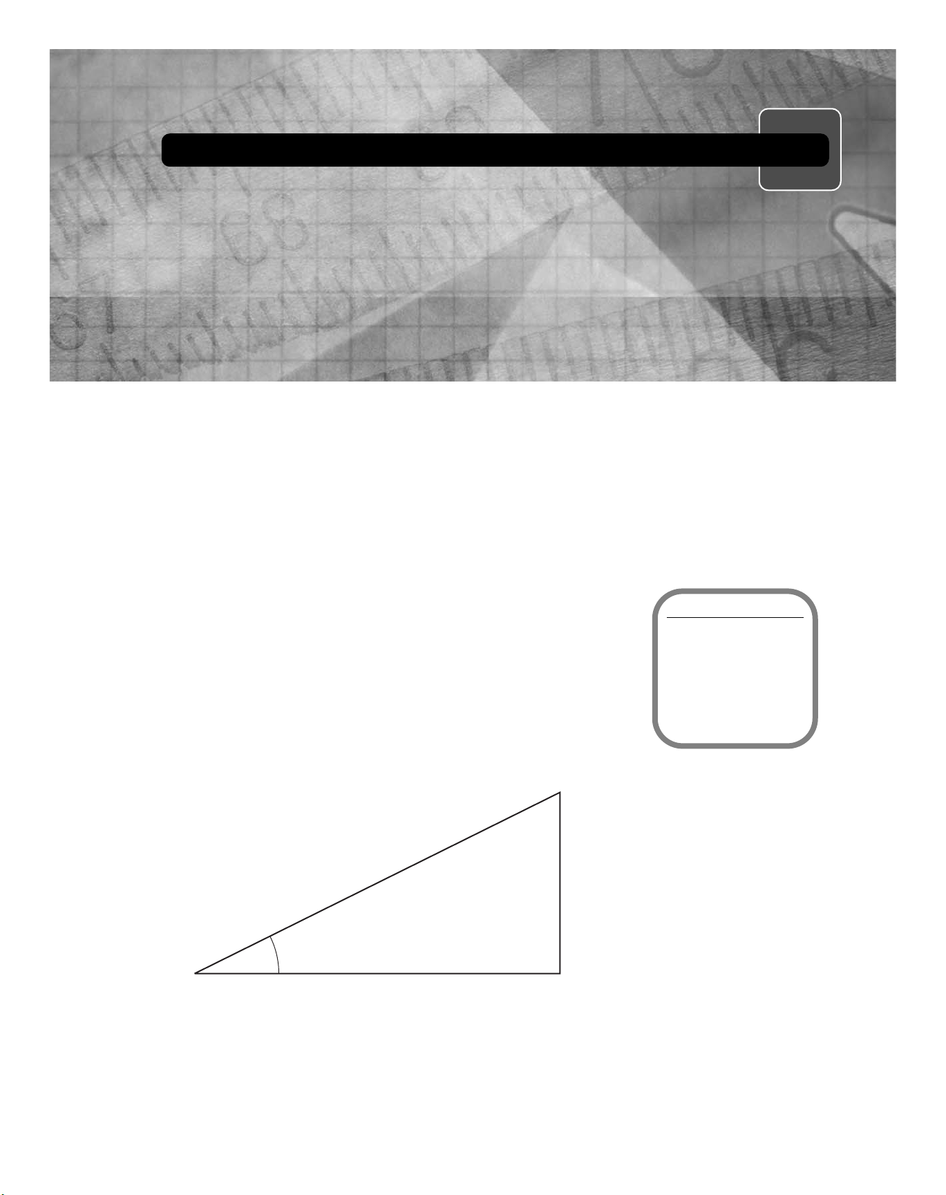
angle having two sides of length Rc as shown in Figure 6-6(a). Side length
“d” opposite the right angle, then, is greater than Rc; in fact, it may be
shown using trigonometry that this side has a length of d ⫽1.414 ⫻Rc.
Figure 6-6(b) and (c) show the pitch triangles for the hip and common
rafters respectively. The hip’s pitch angle (and therefore its plumb cut an-
gle) is Ph ⫽Ri / 1.414 Rc, while that of the common rafter is Pc ⫽Ri / Rc.
Since the hip rafter has the same rise but a longer run than the common
rafter, its pitch will always be less than that of its adjacent common rafters.
The framing members required to make the hip-plate and valley-ridge
connections have varying lengths as shown for the hip rafter in Figure 6-7.
Notes
Copyright © 2007 by Calculated Industries, Inc.
and Thomson Delmar Learning
Construction Master® Pro Workbook and Study Guide

Sample
66 Part C ■Framing
The lengths of these jack rafters for 16⬙center-to-center spacing are easily
obtained from your calculator, as are the plumb cut, level cut, and cheek
cut angles for these members. (Other spacing distances may also be used;
to enter a 24⬙spacing, for example, simply press 2 4 i ß 5.)
■EXAMPLE 6.6
For the framing conditions of Example 6.5, find the required lengths of
jack rafters at an o.c. spacing of 16⬙, as well as the plumb cut, level cut, and
cheek cut angles for these members.
Solution:
Continuing on from the final displayed value (CHK1 45.00°) of Exam-
ple 6.5, successively pressing the jkey first displays the default o.c.
spacing of 16⬙, and the incremental decrease in length for each jack
rafter:
Notes
Construction Master® Pro Workbook and Study Guide
Copyright © 2007 by Calculated Industries, Inc.
and Thomson Delmar Learning
Common
Hip
Common
90°
90°
90°
d
Rc
Ri
Rc
D
B
AC
Figure 6-5
Calculator
Version Note
4065 v3.0: Display of
incremental value does
not appear on this
model.
Calculator Tip
Jacks On-Center: The
calculator’s default
setting for jacks is set to
16 inches on-center.

Sample
Rafters ■Chapter 6 67
KEYSTROKE DISPLAY
jTJKOC 16 INCH
jINCR 1 FEET 8 INCH
This is followed by the lengths of each jack rafter, then by the plumb cut,
level cut, and cheek cut angles:
jJK 1 18 FEET 9 INCH
jJK 2 17 FEET 1 INCH
jJK 3 15 FEET 5 INCH
jJK 4 13 FEET 9 INCH
jJK 5 12 FEET 1 INCH
jJK 6 10 FEET 5 INCH
jJK 7 8 FEET 9 INCH
jJK 8 7 FEET 1 INCH
jJK 9 5 FEET 5 INCH
jJK 10 3 FEET 9 INCH
Notes
Copyright © 2007 by Calculated Industries, Inc.
and Thomson Delmar Learning
Construction Master® Pro Workbook and Study Guide
d⫽1.414 Rc
Common
(b) (c)
D
AC
B
BABC
Rc
Rc
Rc
PcPh
Ri Ri
d⫽1.414 Rc
D
(a)
Hip
45°
45°
Figure 6-6
Calculator Tip
Ascending Jacks: Jack
lengths can be set to
display in ascending
order; see Setting
Preferences in User’s
Guide for more details.

Sample
68 Part C ■Framing
KEYSTROKE DISPLAY
jJK 11 2 FEET 1 INCH
jJK 12 0 FEET 5 INCH
jJK 13 0 FEET 0 INCH
jPLMB 36.87°
jLEVL 53.13°
jCHK 1 45.00°
Roofs containing two different pitches are called irregular or nonstan-
dard roofs. Hip and valley rafters joining roof sections of different pitches
each represent the diagonal of a rectangle as shown in Figure 6-8. For such
constructions, one of the common rafters is designated as having a “regu-
lar pitch,” while the other common rafter (of different pitch) is said to have
an “irregular pitch.” Note from the figure that the number of regular jack
rafters is generally not equal to the number of irregular jack rafters, and
that placement of these rafters may not “match” or coincide, even if an
equal o.c. spacing is used for both sets of jack rafters. All of the required
data for such hip/valley and jack rafters are readily available using your
Construction Master Pro calculator.
Notes
Construction Master® Pro Workbook and Study Guide
Copyright © 2007 by Calculated Industries, Inc.
and Thomson Delmar Learning
Hip
Common
Common
CHK1
JK1 JK2 JK3
Figure 6-7
Calculator Tip
Coinciding Jacks:
Regular and irregular
jacks can be set to
“match” or coincide; see
Setting Preferences in
User’s Guide for more
details.

Sample
Rafters ■Chapter 6 69
■EXAMPLE 6.7
One section of roof having a 6-in. pitch and a run of 9⬘-6⬙is to be joined
with another roof section having an 8-in. pitch. Using the 6-in. value as the
regular pitch, find the length, plumb, level, and cheek cut angles for the hip
rafter and all jack rafters. Use a uniform rafter spacing of 16⬙o.c..
Solution:
KEYSTROKE DISPLAY
First, enter the regular pitch and run, check that the calculator has a stored
rafter spacing of 16⬙o.c., and then enter the irregular pitch:
6 i p PTCH 6 INCH
9 f 6 i R RUN 9 FEET 6 INCH
1 6 i ß 5 T OC 16 INCH
8 i Ç H (Ir/Pitch) IPCH 8 INCH
Successively pressing the Hkey will now display the length of your ir-
regular hip rafter, as well as the values for plumb, level, and both cheek cut
angles:
HIH/V 12 FEET 9-1/2 INCH
HPLMB 21.80°
Notes
Copyright © 2007 by Calculated Industries, Inc.
and Thomson Delmar Learning
Construction Master® Pro Workbook and Study Guide
Common Rafter–Regular Pitch
Common Rafter–Irregular Pitch
Irregular Jacks
Regular Jacks
16” o.c.
16” o.c.
Irregular
Hip
Figure 6-8

Sample
70 Part C ■Framing
KEYSTROKE DISPLAY
HLEVL 68.20°
HCHK 1 36.87°
HCHK 2 53.13°
Your calculator now provides additional information—first on the irregu-
lar jack rafters, then on the regular jack rafters—using this key sequence:
Çj IJOC T16 INCH
jINCR 1 FEET 2-7/16 INCH
jIJ 1 7 FEET 4-5/16 INCH
jIJ 2 6 FEET 1-15/16 INCH
jIJ 3 4 FT 11-1/2 INCH
jIJ 4 3 FEET 9-1/16 INCH
jIJ 5 2 FEET 6-5/8 INCH
jIJ 6 1 FEET 4-1/4 INCH
jIJ 7 0 FEET 1-13/16 INCH
jIJ 8 0 FEET 0 INCH
jPLMB 33.69°
jLEVL 56.31°
jCHK 1 36.87°
jJKOC T16 INCH
jINCR 1 FEET 11-7/8 INCH
jJK 1 8 FEET 7-5/8 INCH
jJK 2 6 FEET 7-3/4 INCH
jJK 3 4 FEET 7-7/8 INCH
jJK 4 2 FEET 8-1/16 INCH
jJK 5 0 FEET 8-3/16 INCH
jJK 6 0 FEET 0 INCH
jPLMB 26.57°
jLEVL 63.43°
jCHK 1 53.13°
Notice that the jack rafters for this problem are arranged in descend-
ing order. Your Construction Master Pro User’s Guide demonstrates the
keystroke sequences required to (a) arrange the rafters in ascending order
with the jacks mating at the hip/valley rafter, and (b) change the rafter spac-
ing to something other than 16⬙o.c.
Notes
Construction Master® Pro Workbook and Study Guide
Copyright © 2007 by Calculated Industries, Inc.
and Thomson Delmar Learning

Sample
Rafters ■Chapter 6 71
The final structural elements to be analyzed are rake-wall studs as
shown in Figure 6-9. These may be used to support the end walls of a gable
roof, or the side walls of a shed roof. These members are essentially just
vertical jacks, and may be installed with no base, or atop a stud wall as
shown in the figure. Pitch of the roof rafters may be specified in the usual
number of ways: rise and run; rise and pitch; run and pitch; or diagonal and
pitch.
Notes
Copyright © 2007 by Calculated Industries, Inc.
and Thomson Delmar Learning
Construction Master® Pro Workbook and Study Guide
Rake Wall w/No Base
Rake Wall w/Base
(a)
(b)
Figure 6-9

Sample
0ART# &RAMING
%8!-0,%
$UDNHZDOOKDYLQJDULVHRI LVWREHDGGHGDWRSDQROGFRQVWUXFWLRQVWXG
ZDOOWKDWLV ORQJDVVKRZQLQ)LJXUH )LQGWKHOHQJWKVRIUDNHZDOO
VWXGVIRUD RFVSDFLQJ DQGWKHUHTXLUHGFKHHNDQJOHIRUWKHVHVWXGV
3OLUTION
.(<6752.( ',63/$<
)LUVWHQWHUWKHULVH UXQ DQGRFVSDFLQJ
(0 5,6()((7,1&+
( 581)((7,1&+
*; 2& ,1&+
$FFHVVLQJWKHUDNHZDOOIXQFWLRQ805:DOODQGWKHQVXFFHVVLYHO\
SUHVVLQJWKH0NH\ZLOOGLVSOD\WKHUHTXLUHGVWXGOHQJWKV DVZHOODVWKH
UDNHZDOODQJOH ZKLFKLVDOVRWKHFKHHNDQJOHWRZKLFKHDFKVWXGVKRXOG
EHFXW
805:DOO 5:2&,1&+
05:)((7,1&+
05:)((7,1&+
05:)((7,1&+
05:)((7,1&+
05:)((7,1&+
0%$6()((7,1&+
05:
.OTES
&RS\ULJKW E\&DOFXODWHG,QGXVWULHV,QF
DQG7KRPVRQ'HOPDU/HDUQLQJ
·
·
&IGURE.OTTOSCALE
&DOFXODWRU7LS
$VFHQGLQJ5DNH:DOO
6WXGV 6WXGOHQJWKVFDQ
EHVHWWRGLVSOD\LQ
DVFHQGLQJRUGHUVHH
6HWWLQJ3UHIHUHQFHV LQ
8VHU·V*XLGHIRUPRUH
GHWDLOV
&DOFXODWRU7LS
5DNH:DOO2Q&HQWHU
7KHFDOFXODWRU·VGHIDXOW
VHWWLQJIRUUDNHZDOOLV
VHWWRLQFKHVRQ
FHQWHU

Sample
2AFTERS #HAPTER
%8!-0,%
$UDNHZDOOKDYLQJDQ EDVH UXQ DQGLQSLWFKLVVKRZQLQ)LJ
XUH )LQGWKHVWXGOHQJWKVIRU RF DQGWKHUDNHZDOODQJOH
3OLUTION
.(<6752.( ',63/$<
(QWHUWKHSLWFK UXQ RFVSDFLQJ DQGKHLJKWRIEDVHDVIROORZV
*/ 37&+,1&+
(* 581)((7,1&+
*; 2&,1&+
(80 %$6()((7,1&+
0 5:2&,1&+
05:)((7,1&+
05:)((7,1&+
05:)((7,1&+
05:)((7,1&+
05:)((7,1&+
05:)((7,1&+
05:)((7,1&+
0%$6()((7,1&+
05:
.OTES
&RS\ULJKW E\&DOFXODWHG,QGXVWULHV,QF
DQG7KRPVRQ'HOPDU/HDUQLQJ
&RQVWUXFWLRQ0DVWHU 3UR:RUNERRNDQG6WXG\*XLGH
·²µ
·
²LQFKSLWFK
&IGURE.OTTOSCALE
&DOFXODWRU7LS
5DNH:DOO%DVH 7R
LQFOXGHDUDNHZDOOEDVH
WKHOHQJWKPXVWDOZD\V
EHHQWHUHGLPPHGLDWHO\
EHIRUHSUHVVLQJ8
0
5:DOO

Sample
74 Part C ■Framing
PROBLEMS FOR CHAPTER 6
P6.1. The common rafters on a particular structure have a 5-1/2⬙pitch
and a run of 13⬘-4⬙. Find the rise, length, plumb and level cut
angles for these rafters.
P6.2. For common rafters having a rise of 8⬘-5⬙and a run of 15⬘-3⬙,
determine the pitch (in inches and degrees), length, plumb and
level cut angles.
P6.3. Common rafters on a shed roof have a 4⬙pitch and a rise of 3⬘-8⬙.
Calculate the run, length, plumb and level cut angles for these
rafters.
P6.4. A conventional roof has two sections containing common rafters
with a 6⬙pitch and 15⬘-9⬙run. For these common rafters, find the
pitch (in degrees), length, plumb and level cut angles. Also
determine the length; plumb, level, and cheek cut angles for hip
and valley rafters used to join the two roof sections.
P6.5. For the roof of problem P6.4, calculate all hip jack lengths for a
spacing of 16⬙o.c. . Repeat for 24⬙o.c. .
P6.6. A conventional roof has a 12⬙pitch and an 8⬘run. Calculate the
pitch (in inches), length, plumb and level cut angles for all
hip/valley rafters used on this roof.
P6.7. For the roof of problem P6.6, find the lengths of all jacks at a
spacing of 24⬙o.c. .
P6.8. An irregular roof contains one section whose common rafters have
a 5⬙pitch and a run of 11⬘-8⬙, and another section having a pitch of
6-1/2⬙. Find the length, plumb, level and cheek cut angles for all
regular and irregular jacks to be used on this roof if their spacing is
24⬙o.c. throughout.
P6.9. A rake wall with no base has a 4⬘-6⬙rise and a 14⬘-0⬙run. Find the
lengths of all rake-wall studs at 24⬙o.c., as well as the cheek angle
to be cut at the top of each stud.
P6.10. A rake wall with an 8⬘-4⬙base has a 5-1/2⬙pitch and a run of
9⬘-10⬙. Determine the rake-wall stud lengths at 16⬙o.c., and the
cheek cut angle for these studs.
Notes
Construction Master® Pro Workbook and Study Guide
Copyright © 2007 by Calculated Industries, Inc.
and Thomson Delmar Learning
Table of contents
Popular Calculator manuals by other brands

SwissMicros
SwissMicros Voyager Series user manual

HP
HP 30b Business Professional brochure

Calculated Industries
Calculated Industries Tradesman Calc 4400 Pocket reference guide

Sharp
Sharp EL-1750V Operation manual

Sentry
Sentry CA308 instruction manual

Texas Instruments
Texas Instruments TI-31 Solar Quick reference guide