Thonk God's Box Lollipop User manual
!
!
November 30th 2018 www.thonk.co.uk 1
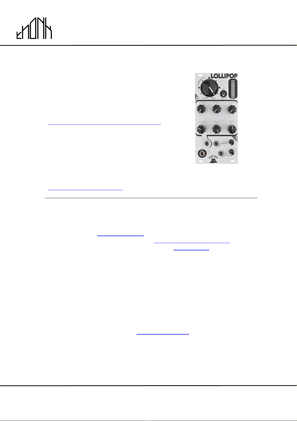
God’s Box Lollipop
Eurorack DIY Kit
Instructions
Version 1
OVERVIEW
For the most recent version of this
document please visit
https://www.thonk.co.uk/documents/gbox
All Thonk kits are sold under our standard Terms and Conditions -
http://www.thonk.co.uk/faq/
DIY INSTRUCTIONS
This document gives detailed instructions that assume you have purchased a
complete kit from www.thonk.co.uk. It also assumes no previous knowledge
of electronics. To learn to solder try http://youtu.be/I_NU2ruzyc4 and the
Adafruit guide to excellent soldering – http://bit.ly/1l77tF4!
Watch and understand that whole YouTube video! If you’re not achieving the
results shown in the video then you need to buy new tools or seek advice.
You will not end up with a working module otherwise.
TOOLS REQUIRED
Soldering iron, snipe nose pliers, wire strippers, small flat head screwdriver
and diagonal cutters AKA snips AKA side-cutters. A Digital Multimeter is
always helpful for checking for bad solder joints and continuity. Thonk sell a
range of inexpensive tools here - http://bit.ly/1jxqF3n
!
!
November 30th 2018 www.thonk.co.uk 2
God’s Box Lollipop
Eurorack DIY Kit
Instructions
Version 1
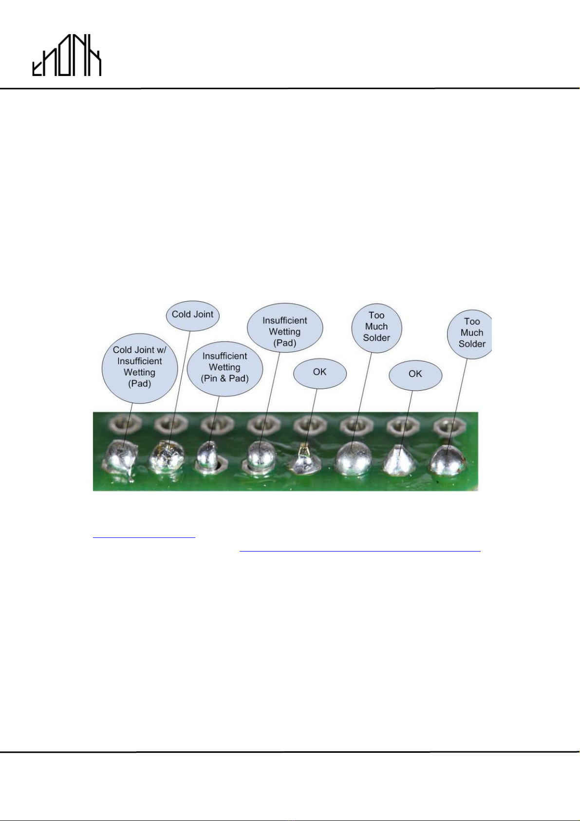
SOLDER JOINTS
Your solder joints should look like those shown as ‘OK’ below, they should
have that neat conical shape on BOTH sides of the PCB. If they don’t look
the same on both sides then stop! Work out why from the soldering guides
linked and don’t continue until you are getting those results.
This isn’t just OCD talking, you are very likely to end up with a destroyed,
damaged or defective unit if you’re not hitting that standard.
This photo is from the Adafruit guide to excellent soldering -
http://bit.ly/1jxqF3n and is reproduced under an Attribution-Sharealike
creative commons license - http://creativecommons.org/licenses/by-sa/3.0/

!
!
November 30th 2018 www.thonk.co.uk 3
God’s Box Lollipop
Eurorack DIY Kit
Instructions
Version 1
LOLLIPOP BUILD INSTRUCTIONS
1.
There are two PCBs used in this build - they are referred to as the top board
and the bottom board. They can be identified by locating the text on each
PCB as shown.
2.
Start by emptying the bag containing
the two PCBs – this will also have the
resistor bags containing the 56K
resistors and single 330K resistor.
There are some instructions printed
on the PCB bag related to the top
PCB – we will now follow them.
!
!
November 30th 2018 www.thonk.co.uk 4
God’s Box Lollipop
Eurorack DIY Kit
Instructions
Version 1
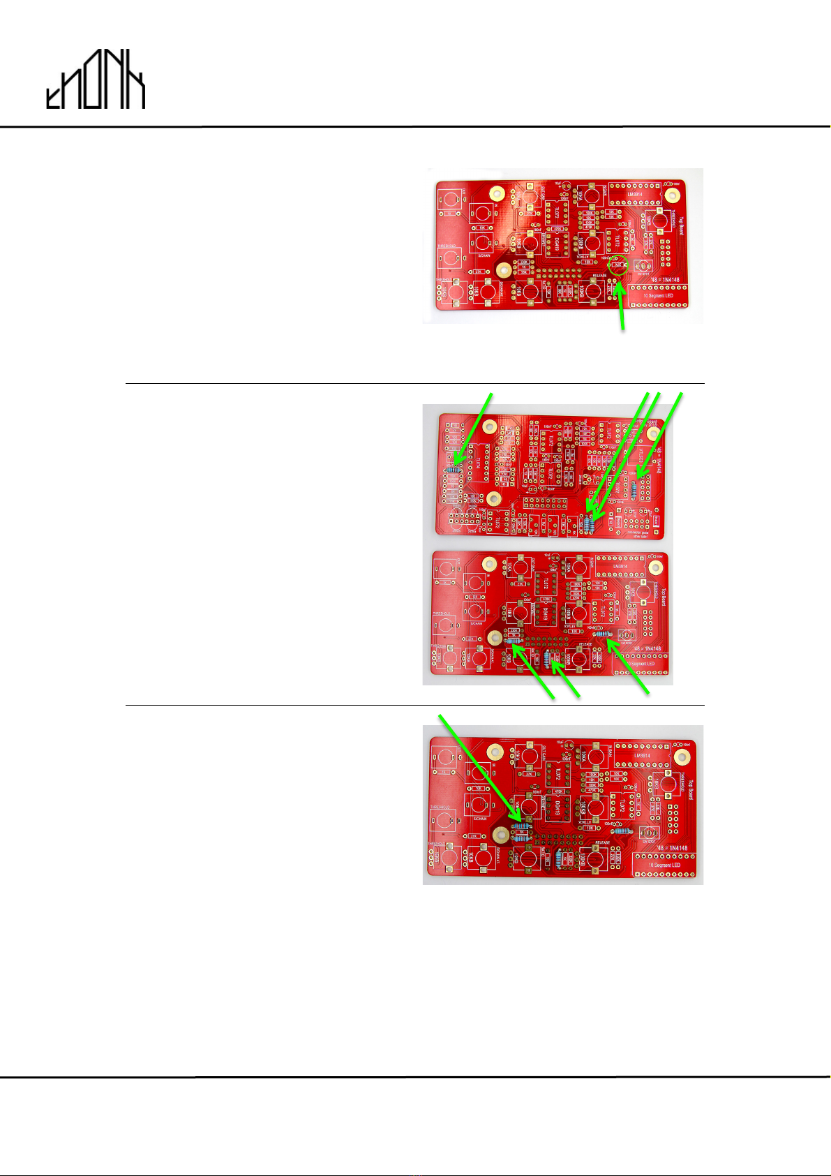
3.
Start by soldering the 56K resistors.
There are seven 56K resistors in
total but one of them should be
soldered into the PCB where it
says 27K as shown.
Top Board
4.
Once all seven 56K resistors have
been soldered the PCBs should look
as pictured.
5.
Next we will solder the single 330K
resistor onto the front board as
shown
NOTE! There are two positions for
330K but one should be left empty.
56K goes here!
!
!
November 30th 2018 www.thonk.co.uk 5
God’s Box Lollipop
Eurorack DIY Kit
Instructions
Version 1
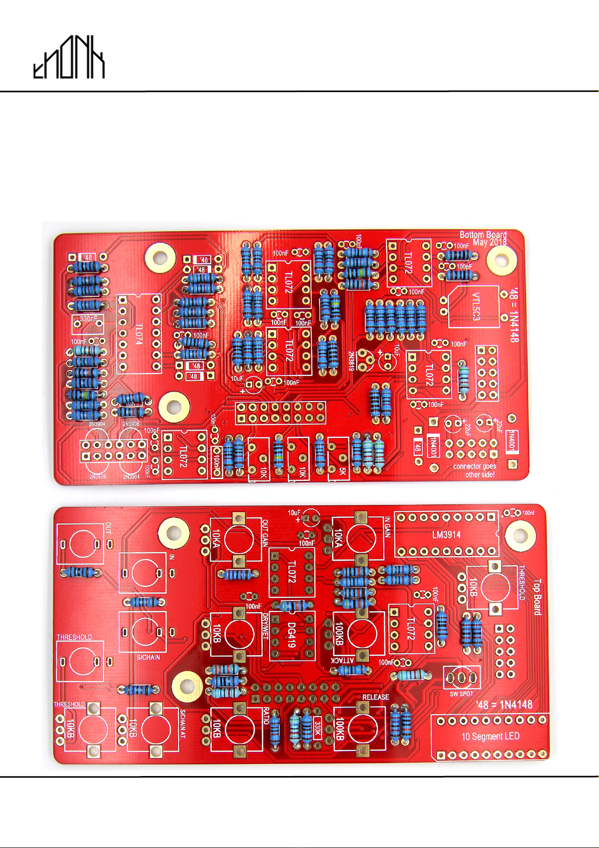
6.
Now you can go ahead and solder all the rest of the resistors for the top and
bottom boards. All resistors from this point onwards should be soldered with
exactly the values as shown on the PCB legend
It is recommended you do this gradually – one value at a time.
!
!
November 30th 2018 www.thonk.co.uk 6
God’s Box Lollipop
Eurorack DIY Kit
Instructions
Version 1
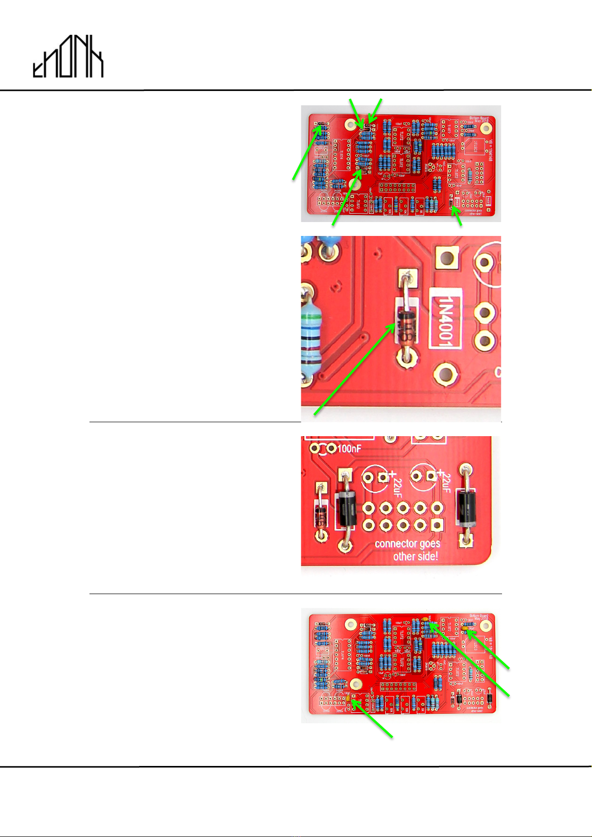
7.
Next we’re going to solder in the
diodes, starting with the 6 x 1N4148.
These are orange coloured with a
black stripe and labelled on the PCB
as ’48.
NOTE: Take care with the orientation
of the black stripes on the diodes –
these should match the thick white
lines on the PCB silkscreen.
NOTE! Do not heat the diodes
excessively or you will damage them,
you should be aiming to solder
quickly and neatly.
8.
Next solder the two 1N4001 diodes.
These are black with a silver stripe
NOTE: Take care with the orientation
of the silver stripes which should
match the thick white lines on the
PCB silkscreen.
9.
Next solder in the three 100pF
capacitors on the bottom board.
!
!
November 30th 2018 www.thonk.co.uk 7
God’s Box Lollipop
Eurorack DIY Kit
Instructions
Version 1
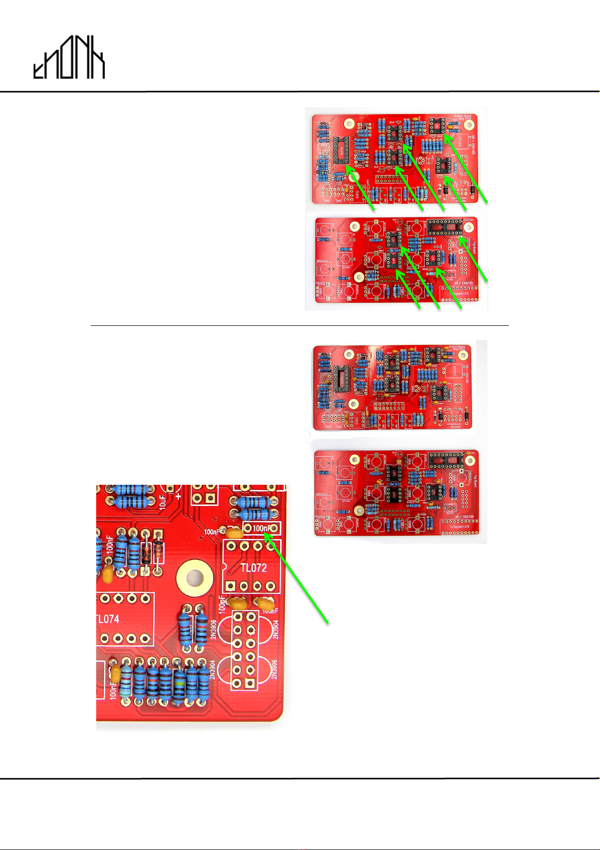
10.
Now solder in the IC sockets on both
PCBs. Make sure these sockets are
soldered flush and perpendicular to
the PCB surface.
The notch on each socket should
match the PCB silkscreen as shown.
11.
Next solder in the seventeen ceramic
100n capacitors
Note! there are two different types of
100n capacitor in this kit. Do not
solder a ceramic cap into the
position below.
DO NOT solder a ceramic cap
here

!
!
November 30th 2018 www.thonk.co.uk 8
God’s Box Lollipop
Eurorack DIY Kit
Instructions
Version 1
12.
Next identify the 100n and 330n box
film capacitors. These are located in
the capacitor bag.
13.
Now take the 100n red box capacitor and solder it into position
14.
Next solder the 330n red box capacitor.
100n
330n
!
!
November 30th 2018 www.thonk.co.uk 9
God’s Box Lollipop
Eurorack DIY Kit
Instructions
Version 1
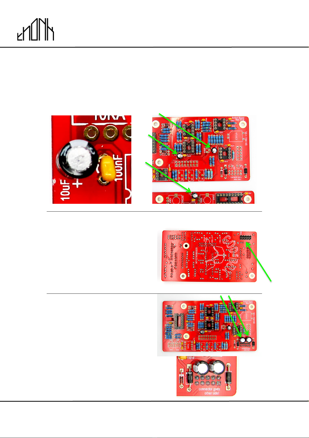
15.
Now solder in the three 10uF Electrolytic Capacitors.
NOTE! Orientation is vital on this part. The grey stripe and shorter leg signifify
the negative side of the capacitor, the longer lead of the component should
go into the hole marked + on the PCB.
16.
Next solder in the 10 pin male power
header on the back of the bottom
board as shown.
NOTE: Make sure this header is
soldered on the opposite side of all
other components as shown in the
picture.
Bottom Board
17.
Next solder in the two 22uF
Electrolytic Capacitors
NOTE: Orientation is vital on this
part. The grey stripe should be
positioned as pictured, the longer
lead of the component should go into
the hole marked + on the PCB.

!
!
November 30th 2018 www.thonk.co.uk 10
God’s Box Lollipop
Eurorack DIY Kit
Instructions
Version 1
18.
Now solder in the two 2N3904
transistors
NOTE! Orientation matters – be sure
to match the curve of the body to the
PCB silkscreen.
Do not heat this part excessively or
you will damage it, you should be
aiming to solder quickly and neatly.
19.
Now solder in the two 2N3906
transistors
NOTE! Orientation matters – be sure
to match the curve of the body to the
PCB silkscreen.
Do not heat this part excessively or
you will damage it, you should be
aiming to solder quickly and neatly.
20.
Now solder the single 2N3819
transistor
NOTE! Orientation matters – be sure
to match the curve of the body to the
PCB silkscreen.
Do not heat this part excessively or
you will damage it, you should be
aiming to solder quickly and neatly.
!
!
November 30th 2018 www.thonk.co.uk 11
God’s Box Lollipop
Eurorack DIY Kit
Instructions
Version 1
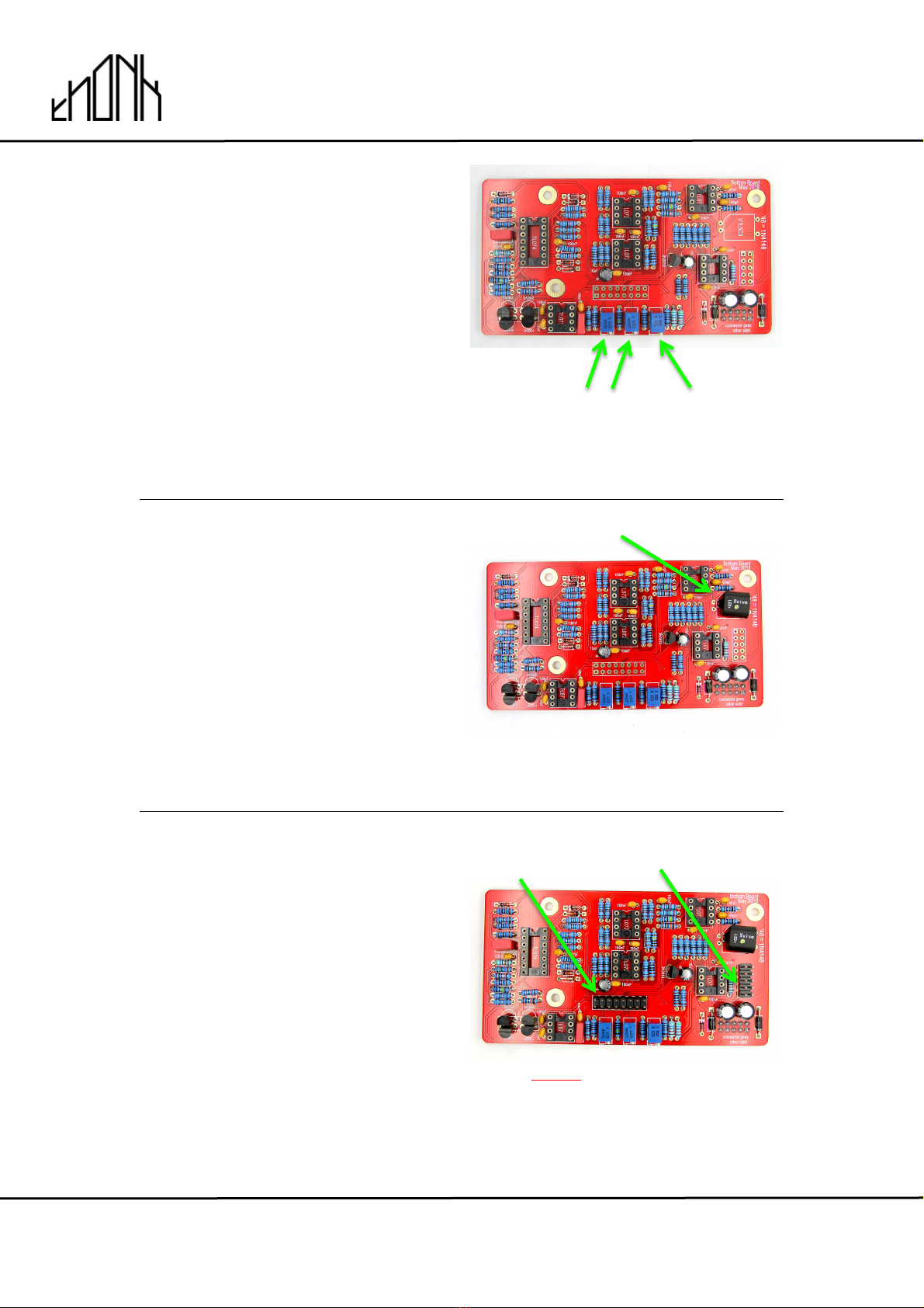
21.
Next solder the single 5K trimmer
and the two 10K trimmers.
NOTE! Orientation matters - make
sure the brass screws are pointing
away from the centre of the PCB.
22.
Next take the Vactrol and solder into
place as shown. The orientation of
the 4 pins is vital. The Vactrol should
be placed completely flat to the top
surface of the PCB.
NOTE! Do not heat this part
excessively or you will damage it,
you should be aiming to solder
quickly and neatly.
23.
Next place and solder the remaining
2x5 male header and the 2x8 male
header to the bottom board - these
are placed on the same side as the
resistors and capacitors as shown.
These should be soldered flush and
perpendicular to the PCB surface.
Bottom Board
NOTE! Don’t solder these headers to
the other side of the board like the
power header you already soldered!
10K 5K

!
!
November 30th 2018 www.thonk.co.uk 12
God’s Box Lollipop
Eurorack DIY Kit
Instructions
Version 1
24.
Now switch to the top board and
place but DO NOT SOLDER the 2x5
and 2x8 (or two 1x8) female headers
onto the top board. The female
headers sit on the opposite side to all
other components.
Before soldering these headers –
connect them to the male headers on
the bottom PCB. Once you have the
PCBs connected nicely with the
headers sitting flush you can then
solder them in place.
Now is also a good time to screw the
spacers onto the top board.
SWITCH TO OTHER PCB!
Top Board
25.
Now disconnect the PCBs and place
but DO NOT SOLDER the pots,
jacks, LED bar and switch.
Be sure to match the pot values to
the PCB silkscreen as shown. Screw
just one of the nuts onto the switch
- do not use the switch washer.
26.
NOTE! Orientation matters for the
LED bar. One of the corners is
flattened - make sure you align this
with the PCB silkscreen. Now you
can carefully place on the front panel
and screw the nuts and washers onto
the pots, jacks and switch.!
NOTE: Read the next step before
soldering the LED bar
B100K
B10K
B10K
A10K
Flat Edge
Flat Edge on
Silkscreen

!
!
November 30th 2018 www.thonk.co.uk 13
God’s Box Lollipop
Eurorack DIY Kit
Instructions
Version 1
27.
The module looks much nicer when
the LED bar is soldered flush to the
front panel. Secure the panel by
screwing a few nuts and washers
onto the pots, then make sure the
LED bar is lined up straight to the
panel hole.
It’s a good idea to solder a single
edge pin of each row and then check
that it’s still lined up straight before
proceeding with the rest of the solder
joints – this way you can still re-
position it if required.
28.
Now add a few nuts to the jacks and
switch to hold the panel in place and
then solder in all the pots, jacks and
switches.
29.
Now remove the panel and fit all the
ICs into their sockets as shown
NOTE! Orientation is vital for all ICs
For the seven TL072 make sure the
black circle on the top face of the IC
is facing the end with the notch in the
IC socket as pictured.
For all other chips make sure the
notch in the chip is at the side with
the notch in the IC socket.
TL074
TL072
TL072
TL072
LM3914
DG419

!
!
November 30th 2018 www.thonk.co.uk 14
God’s Box Lollipop
Eurorack DIY Kit
Instructions
Version 1
30.
Now connect the two PCBs together
and secure the three spacers with
screws.
Then you can replace the frontpanel
and screw everything on and place
the seven knobs onto the pots.
31.
The module is now complete. Affix
the power cable as shown with the
red stripe down – and facing the text
on the PCB that says ‘RED’
The trimming and calibration process
is detailed in the God’s Box
documentation linked below.
32.
The Lollipop calibration instructions can be found here:
www.thonk.co.uk/documents/gbox/lollipop/lollipop%20calibration.pdf
More info on God’s Box modules can be found at http://godsbox.co.uk
Other Thonk Music Pedal manuals


