Thorne & Derrick Cembre B1300-UC Installation guide

1
BATTERY OPERATED HYDRAULIC CRIMPING TOOL
PRESSE HYDRAULIQUE SUR BATTERIE
HYDRAULISCHES AKKU-PRESSWERKZEUG
HERRAMIENTA HIDRÁULICA DE CRIMPADO A BATERÍA
UTENSILE OLEODINAMICO DA COMPRESSIONE A BATTERIA
B1300-UC B1300-UCA B1300-UCE B1300-UCT
ENGLISH
FRANÇAIS
DEUTSCH
ESPAÑOL
ITALIANO
Certified Environmental
Management System Certified Occupational
Health & Safety
Management System
Certified Quality
Management System
OPERATION AND MAINTENANCE MANUAL....................................7
NOTICE D’UTILISATION ET ENTRETIEN........................................... 17
BEDIENUNGSANLEITUNG................................................................... 27
MANUAL DE USO Y MANTENIMIENTO........................................... 37
MANUALE D’USO E MANUTENZIONE............................................. 47
15 M 027
2
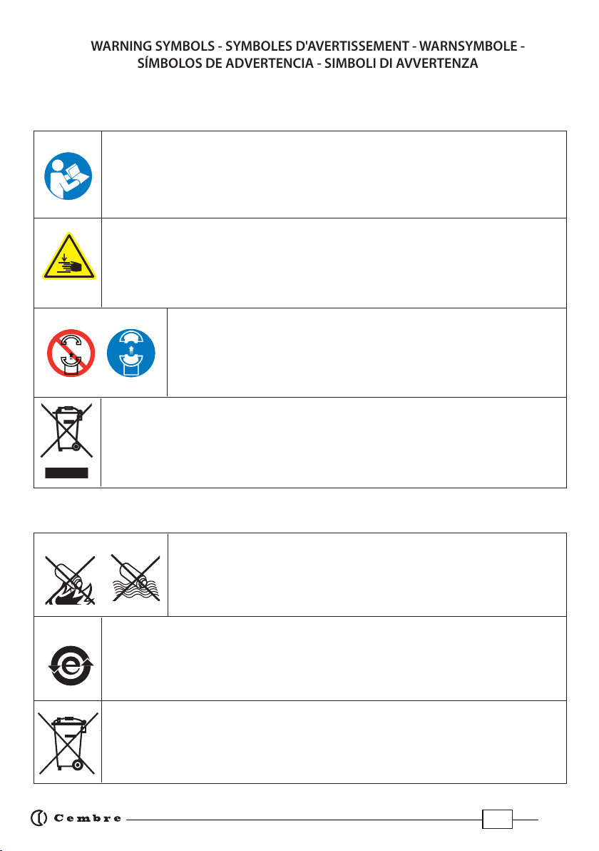
– Before using the tool, carefully read the instructions in this manual.
– Avant d'utiliser cet outil, lire attentivement les instructions de cette notice.
– Vor Inbetriebnahme unbedingt die Bedienungsanleitung durchlesen.
– Antes de utilizar la herramienta, leer atentamente las instrucciones en este manual.
– Prima di utilizzare l'utensile, leggere attentamente le istruzioni riportate in questo manuale.
– When operating the tool, keep hands away from the danger zone.
– Au cours du sertissage, tenir les mains éloignées de la zone de travail.
– Während des Verpressens nicht mit den Händen in den Pressbereich gelangen.
– Durante su utilización, mantenga las manos fuera de la zona de peligro.
– Durante l'utilizzo, mantenere le mani fuori dalla zona di pericolo.
– Do not operate when dies are not in place.
– Insérer les matrices avant d'actionner l'outil.
– Nicht ohne Presseinsatzpaar betätigen.
– No poner en presión sin matrices.
– Non mandare in pressione l'utensile senza le matrici inserite.
WARNING SYMBOLS - SYMBOLES D'AVERTISSEMENT - WARNSYMBOLE -
SÍMBOLOS DE ADVERTENCIA - SIMBOLI DI AVVERTENZA
– Never throw batteries into re or water.
– Jamais jeter les batteries dans le feu ou dans l'eau.
– Werfen Sie Akkus nicht ins Feuer oder Wasser.
– Nunca tire las baterías al fuego o al agua
– Mai gettare le batterie nel fuoco o in acqua.
– Always recycle the batteries.
– Recycler toujours les batteries.
– Verbrauchte Akkus stets dem Recycling zuführen.
– Reutilizar siempre las baterías.
– Riciclare sempre le batterie.
– Do not discard batteries into domestic refuse or waste disposal.
– Ne pas jeter de batteries dans une poubelle ou autre lieu non prévu à cet eet.
– Verbrauchte Akkus nicht der allgemeinen Abfallentsorgung zuführen.
– No tirar las baterías al cubo de basura o lugar parecido.
– Non buttate le batterie fuori uso nei cestini della spazzatura o luoghi simili.
– User information (Directives 2002/95/EC and 2002/96/EC), see page 58.
– Information pour les utilisateurs (Directives 2002/95/CE et 2002/96/CE) voir page 58.
– Information für den Benutzer (Richtlinien 2002/95/EG und 2002/96/EG) siehe Seite 58.
– Informe para los usuarios (Directivas 2002/95/CE y 2002/96/CE) vease página 58.
– Informazione agli utenti (Direttive 2002/95/CE e 2002/96/CE) vedere pagina 58.
Battery -Batterie - Akku - Batería - Batteria
Tool - Outil - Werkzeug - Herramienta - Utensile

3
1
OPERATING BUTTON / GACHETTE DE COMMANDE / STARTKNOPF / BOTÓN DE ACCIONAMIENTO
/ PULSANTE DI AZIONAMENTO
2
PRESSURE RELEASE BUTTON / GACHETTE DE DECOMPRESSION / DRUCKABLASSKNOPF /
BOTÓN DESBLOQUEO PRESIÓN / PULSANTE SBLOCCO PRESSIONE
3
LEDWORKLIGHT / ECLAIRAGE PAR LED / LED-BELEUCHTUNG / LUCES LED / ILLUMINAZIONE LED
4
ADAPTOR / ADAPTATEUR / ADAPTER / ADAPTADOR / ADATTATORE AU130-C
5
U-HEAD / TETE U / U-KOPF / CABEZA U / TESTA A U
6
HANDLE / POIGNEE / GRIFF / EMPUÑADURA / IMPUGNATURA
7
TOUCH BUTTON FOR MENU SELECTION / TOUCHE POUR SELECTIONNER LE MENU / TOUCH-
TASTE FÜR AUSWAHLMENÜ / TECLA PARA SELECCIONAR EL MENÚ / TASTO A SFIORAMENTO
PER SELEZIONE MENU
8
RING FOR SHOULDER STRAP / ANNEAU POUR BANDOULIERE / TRAGERIEMENRING /
ANILLO PARA CORREA / ANELLO AGGANCIO TRACOLLA
9
DISPLAY / ECRAN / DISPLAYANZEIGE / PANTALLA / DISPLAY
10
BATTERY / BATTERIE / AKKU / BATERÍA / BATTERIA
11
BATTERY RELEASE /
DEBLOCAGE BATTERIE / AKKU ENTRIEGELUNG / DESBLOQUEO
BATERÍA /
SBLOCCO BATTERIA
12
HANDLE / POIGNEE / GRIFF / EMPUÑADURA / IMPUGNATURA
FIG. / BILD 1
3
8
5
36
11
9
10
2
1
7
8
12
4
4
FIG. / BILD 2
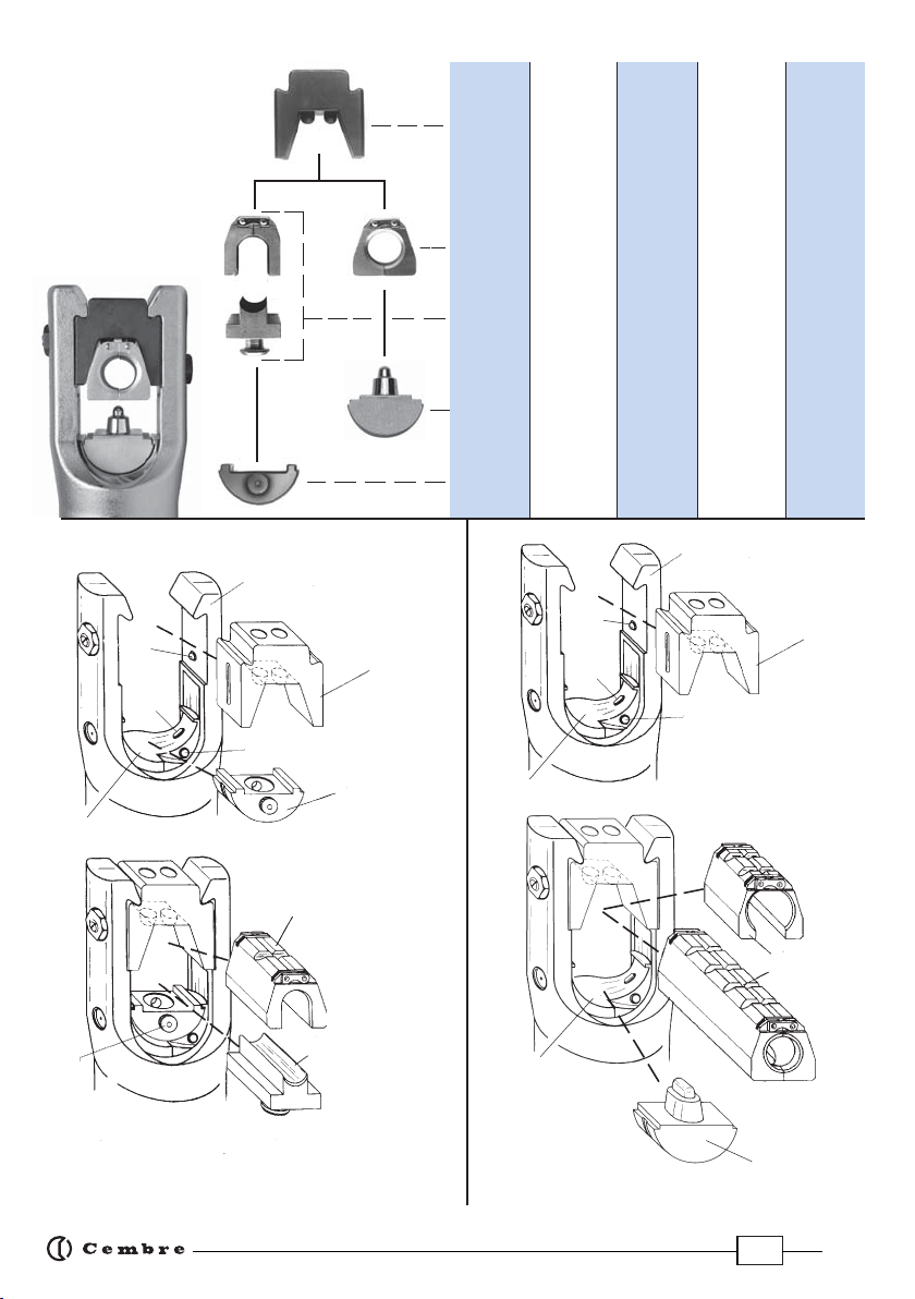
ACCESSORIES
ACCESSOIRES
ZUBEHÖR
ACCESORIOS
ACCESSORI
Matrice
MV..
Adattatore
AC130-P
Matriz
MV..
Matrize
MV..
Adaptador
AC130-P
Adapter
AC130-P
MV..
Die
AC130-P
Adaptor
AU130-150
AU130-240
Adaptor
Adapter
AU130-150
AU130-240
Adaptador
AU130-150
AU130-240
Adattatore
AU130-150
AU130-240
UP...
Rounding
set
Runddrück-
set
UP...
Preredon-
deador
UP...
Prearroton-
datore
UP...
PS...
Indentor
Stempel
PS...
Punzón
PS...
Punzone
PS...
Adaptateur
AU130-150
AU130-240
Matrice
MV..
Matrice de
mise au rond
UP...
Poinçon
PS...
Adaptateur
AC130-P
10
AU130-150
AU130-240
04
AC130-P
06
02
92
95
94
14
96
PS130-.../E
04
10
02
06
14
14
FIG. / BILD 3a FIG. / BILD 3b
AU130-150
AU130-240
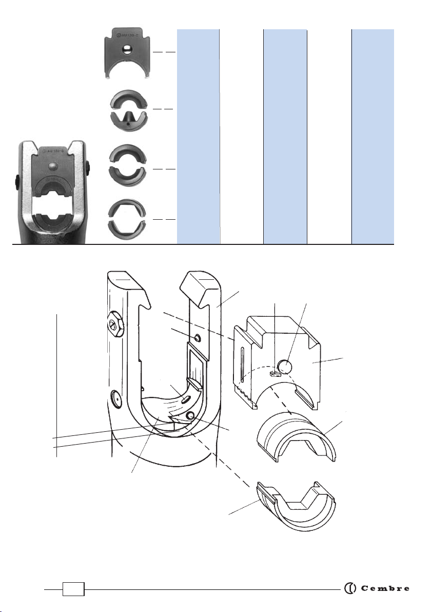
5
Hexagonal
dies
Sechskant
Presseinsätze
Matrices
hexagonales
Matrici
esagonali
Circular
dies
Rundpress-
einsätze
Matrices
semicircu-
lares
Matrici
semicircolari
Nest
and
Indent
dies
Matrize
und
Stempel
Matriz
y
punzón
Matrice
e
punzone
Adapter
AU130-C
Adattatore
AU130-C
Adaptador
AU130-C
AU130-C
Adaptor
Adaptateur
AU130-C
Matrice
et
Poinçon
Matrices
circulaires
Matrices
hexagonales
04
88
AU130-C
08
07
10
06
02
14
89
FIG. / BILD 4
ACCESSORIES
ACCESSOIRES
ZUBEHÖR
ACCESORIOS
ACCESSORI
~ 8 - 10 mm (0.3 - 0.4 in.)
FIG. / BILD 5
FIG. / BILD 3

6
UP 130-25
UP 130-35
UP 130-50
UP 130-70
UP 130-95
UP 130-120
UP 130-150
UP 130-185
UP 130-240
UP130-300
10 - 16
25
35
50
70
95
120
150
185
240
300
AC 130-P
AU 130-150
AU 130-240
PS 130-35/E
MV 35 MVM 35 MUA 35
CONNECTORS - CONNECTEURS - VERBINDER - CONECTORES - CONNETTORI
CAA..-M MTMA... MTA... AA...-M
MTA..-C
Conductor section
Section conducteur
Leiter Querschnitt
Sección cable
Sezione cavo
( mm2 )
Upper adaptor
Adaptateur superieur
Oberen Adapter
Adaptador superior
Adattatore superiore
Lower adaptor
Adaptateur inferieur
Unteren Adapter
Adaptador inferior
Adattatore inferiore
Pre-rounding die
Matr. de mise au rond
Runddrückeinsätze
Preredondeador
Prearrotondatore
Indentor
Poinçon
Stempel
Punzón
Punzone Long - Longue - Lang - Larga -Lunga
Universal - Universelles
Universal - Universale
Universale
Containing die - Matrice coquille - Haltematrize -
Matriz de sujeción - Matrice di contenimento
Short - Courte -
Kurz - Corta - Corta
PS 130-95/E
MV 95 MVM 95 MVC 95 MUA 95
PS 130-150/E
MV 150 MVM 150 MVC 150 MUA 150
MUA 300-34
Aluminium
Aluminio
Alluminio
MV 240 MVM 240 MVC 240 MUA 240
*
PS 130-240/E
Outside diameter of connector = 34mm
Diametre exterieur connecteur = 34mm
Verbinder Aussendurchmesser = 34mm
Diametro externo conector = 34mm
Diametro esterno connettore = 34mm
GUIDE TO THE SELECTION OF ACCESSORIES GUIDE POUR LA SELECTION DES ACCESSOIRES ZUBEHÖR FÜR DIE
TIEFNUTKERBUNG GUIA PARA LA ELECCIÓN DE ACCESORIOS GUIDA PER LA SCELTA DEGLI ACCESSORI
*

7
(1) Directive 2006/42/EC, annexe 1, point 1.7.4.2 letter u)
LpA
= weighted continuous acoustic pressure level equivalent.
LpCPeak
= maximum value of the weighted acoustic displacement pressure at the work place.
LWA
= acoustic power level emitted by the machine.
(2) (Directive 2006/42/EC, annexe 1, point 2.2.1.1)
Weighted root mean square in frequency of the acceleration the upper limbs are exposed to for each biodynamic
reference axis. Tests carried out in compliance with the indications contained in UNI ENV 25349 and UNI EN 28662
part 1st Standards, and under operating conditions much more severe than those normally found.
1. GENERAL CHARACTERISTICS
ENGLISH
B1300-UC B1300-UCE B1300-UCT B1300-UCA
Application range suitable for installing electrical compression connectors
forconductorsup to400mm2(800MCM)and Aluminium
conductors up to 300 mm2(600 MCM)
Rated crimping force
kN (US sh. ton)
132 (14.84)
Minimum crimping force
kN (US sh. ton)
125,2 (14.07)
Minimum operating pressure
bar (psi) 692 (10037)
Dimensions (ref. to Fig. 6) mm (inches) 423 x 239 x 102,5 (16.6 x 9.4 x 4)
Weight with battery kg (lbs) 6,5 (14.3)
Motor V DC 18
Operating temperature °C (°F) -15 to +50 (+5 to +122)
Recommended oil AGIP ARNICA 32 or equivalents
Operating speed twin speed operation and automatic switching from
a rapid advancing speed of the ram to a slower, more
powerful crimping speed
Safety maximum pressure valve
Rechargeable battery V / Ah / Wh 18 / 4.0 / 72
Type CB1840L (Li-Ion)
Weight kg (lbs) 0,66 (1.45)
Battery charger
ASC30-36
Input
type EU
27044000
UK
27045000
AUS/NZ
27047000
USA/CAN
27046000
V / Hz 220 - 240 / 50 - 60 115 / 60
W85
Acoustic noise (1)
LpA dB (A)
66,9
LpCPeak dB (C) 86,9
LWA dB (A) 74,9
Vibration (2) m/s20.398 max.

8
ENGLISH
WARNING
Do not use the tool for purposes other than those intended by Cembre.
The operator should concentrate on the work being performed and be
careful to maintain a balanced working position.
Before starting work on electrical equipment, please ensure that either
there are no live parts in the immediate working area or that precautions
are taken for working near live parts in accordance with EN50110-1.
Do not use this tool on or near energised conductors without proper
personal protective equipment. Failure to observe this warning could
result in severe injury or death.
The tool is unsuitable for continuous use and should be allowed to cool
down following uninterrupted, successive crimping operations; for instance,
having exhausted a fully charged battery in one session, delay battery
replacement for a few minutes.
Protect the tool from rain and moisture. Water will damage the tool and
battery. Electro-hydraulic tools should not be operated in pouring rain.
2. INSTRUCTIONS FOR USE
IMPORTANT: Never pressurise the tool without inserting the dies, this could cause
damage to the head and the ram.
The part reference includes the following (Ref. to Fig. 7 page 57):
– Hydraulic crimping tool.
– AU130-C upper adaptor.
– Li-Ion rechargeable battery (2 pcs).
– Battery charger (model depends on the tool version).
– Shoulder strap.
– Plastic carrying case.
– USB cable (Ref. to § 8).
Thetool issuppliedwiththeAU130-Cupperadaptor,whichwillacceptsemicircularslotteddies(com
mon to Cembre 130 kN tooling) suitable for:
Circular or hexagonal compression on Copper, Aldrey, Aluminium or ACSR conductors.
Indentation on Copper conductors.
With the upper adaptor AU130-150, AU130-240 and lower adaptor AC130-P, the tool can accept:
Pre-rounding dies UP130-... used for converting Aluminium sectoral conductor to a compact,
round section.
Containing dies MV, MVC, MVM, MUA series to crimp connectors on Aluminium cables using
the deep indent crimping system.
9
ENGLISH
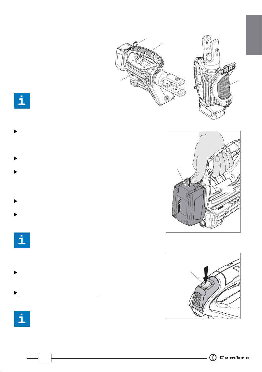
2.1) Preparation
The tool can be easily carried using either the main handle (12) or the shoulder strap attached
to the two rings (8).
Themainoperatingpositionsare:hori-
zontal standing on its feet and vertical
standing on its battery. In addition to
the main handle (12) the lower handle
(6) allows a safer and more balanced
grip when using two hands to hold
the tool.
Before starting any work, check
the battery charge (Ref. to § 2.8) and recharge if
necessary, following the instructions in the battery charger user manual.
To replace the battery, grip the tool as illustrated in Figure;
press the release button (11) and push the battery downward
unlocking it. Insert a charged battery from the bottom by sli-
ding it into the guides until it locks.
The display shows the operational parameters of the tool; to
customise them proceed as described in § 2.7.
Depending on the compression to be performed, proceed as
described in § 4 or 5.
2.2) Die advancement
Press operating button (1) to activate the motor-pump and
advance the lower die.
To halt the advancement, release operating button and the
motor will cut out.
Make sure the dies are exactly positioned on the
desired crimp point otherwise re-open dies following
instructions as per § 2.4 and reposition the connector.
2.3) Compression
By keeping operating button (1) pressed, the motor con-
tinues to operate: the ram will gradually move forward
until the two dies touch.
The motor will stop automatically when the set pressure
has been reached.
To perform proper compression, press and hold the
operating button (1) until the motor stops automati-
cally.
11
Battery
6
12
8
8
1

10
ENGLISH
NOTE: To display the momentary force or pressure dur-
ing the work cycle, select the appropriate display from
the menu (Ref. to § 7). When the operating button is
releasedbeforethemotorstopsautomatically,thedisplay
will show the peak force (Fp) or the peak pressure (Pp)
reached at that instant.
Tocomplete thework, pressthe operatingbutton againuntil themotor stopsautomatically; the dis-
playwillshow themaximum forceor pressurereachedfollowedby ‘OK’to conrmcorrect operation.
The display ‘ERROR’, combined with a beep and the LEDs ashing, indi
cates an incorrect crimping procedure caused by the work cycle being
interruptedbeforethecontrolparameters(force/pressure)ofthetoolarereached.
This error appears when the pressure release button has been operated and the tool has already
reached a pressure > 100 bar. In this case, repeat the compression by pressing and holding the
operating button until the motor stops automatically.
2.4) Release of dies
By operating the pressure release button (2) , the ram will retract
and open the dies.
2.5) LED Worklights
Whilst the tool is in operation, the compression area is illuminated
by two high luminosity LED Worklights that switch o automatical-
ly at the end of the cycle.
The LED Worklights can be disabled by following the procedure described in § 7.2.
2.6) Head rotation
For ease of operation, the tool head can rotate through 180°, allowing the operator
to work in the most comfortable position.
Do not attempt to rotate the head when the hydraulic circuit is pressurised.
2.7) Capacitive touch button for menu selection
This button is located under the display and allows selection of
various screens (Ref. to § 7); it only works when the display is on.
Wearing gloves or using other objects may inhibit the operation of the
button, therefore use a bare nger to apply only a light touch.
Do not apply pressure to or stab at the touch button, a light touch using a bare nger is
sucient. The command pulse is sent when the nger releases the button.
ERROR
Ï
Ð
Fm= 125.2 kN
Fp= 102.3 kN
Pm= 692 bar
Pp = 565 bar
Fm= 125.2 kN
OK
Pm= 692 bar
OK
3 SEC.
2

11
ENGLISH
2.8) Battery status
The battery is equipped with LED indicators that indicate the
remaining battery life at any time by pressing the adjacent
button (P):
4 LEDs illuminated: fully charged
2 LEDs illuminated: 50 % capacity
1 LED flashing : minimum charge, replace the battery.
With the battery inserted into the tool, the remai-
ning battery life can also be checked on the display,
via touch button selection (Ref. to § 7).
The screen shown alongside indicates that the battery Vage has
dropped below a minimum safety threshold; under these conditions
the tool will not start, and it is necessary to recharge or replace the battery.
The approximate time to fully recharge a battery is about 80 minutes.
Aftereach workingcycle,and aftertheextractionofthe batteryfrom thetool,an integrated
battery cut-o device will operate after 70 s approx.
Thenthe LED nearestto button(P) willash 5times each14 sapprox. Thebatterywill be reactivated
when it is reintroduced into the tool and the operating button is pressed.
2.9) Using the battery charger
Carefully follow the instructions in the battery charger user manual.
3. MAINTENANCE
The tool is robust, completely sealed, and requires very little daily maintenance.
Compliance with the following points, should help to maintain its optimum performance:
3.1) Thorough cleaning
Dust, sand and dirt are a danger for any hydraulic device.
Every day, after use, the tool must be wiped with a clean cloth taking care to remove any residue,
especially close to pivots and moveable parts.
Do not use Hydrocarbons to clean the rubber parts.
3.2) Storage case (Ref. to Fig. 7)
When not in use, the tool should be stored and transported in the plastic case, to prevent damage.
The case, type VAL P41, is suitable for storing the tool, the accessories and up to 11 die sets and
pre-prepared compression connectors.
VAL P41: size 691x456x176 mm (27.2x17.9x6.9 inches). Weight 4 kg (8.8 lbs).
Is available VAL 130 steel case: size 360x280x48 mm (14.17x11x1.89 in.), weight 3 kg (6.62 lbs), for
storage of the accessories for crimping Aluminium connectors with deep indent crimping system..
BATTERY Ï
Ð
max.
BATTERY BATTERY
Ï
Ð
min.
P
12
ENGLISH
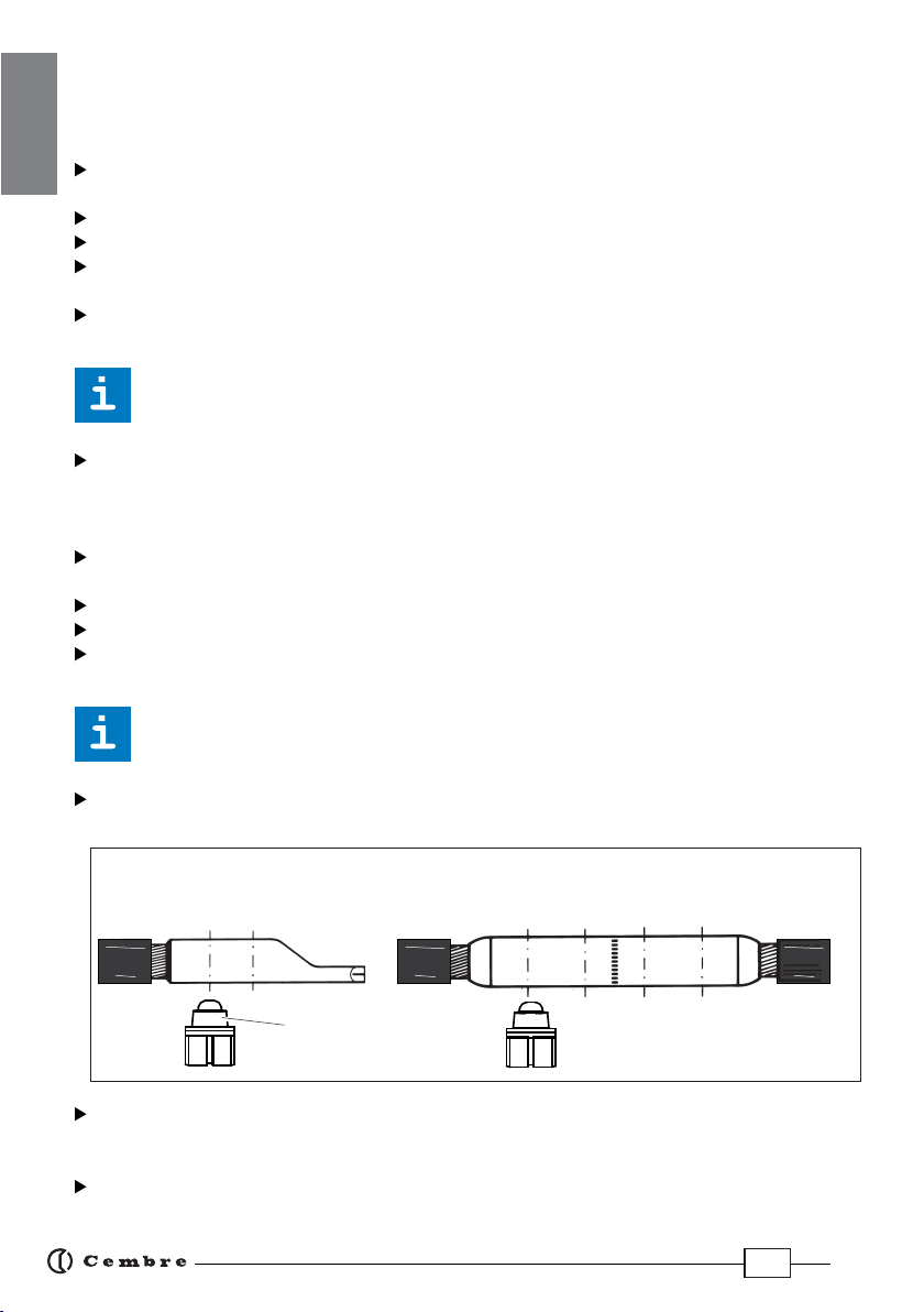
4.CRIMPING OF CONNECTORS ON ALUMINIUM CABLES USING THE DEEP INDENT
CRIMPING SYSTEM (Ref. to Figs. 2, 3)
4.1) Pre-rounding conductor (for sectoral cables) (Ref. to Fig. 3a)
From the table on page 6 select the proper AU130-150 or AU130-240 upper adaptor and UP...
pre-rounding die for the appropriate conductor size to be rounded.
Insert the upper adaptor into the head (see § 6.1).
Insert the lower adaptor AC130-P into the ram (see § 6.2).
Insert the lower part of the pre-rounding die (94) into the AC130-P adaptor by pulling the release
button (92).
Position the conductor into the upper part of the pre-rounding die (95) and locate the pre-
rounding die in the adaptor AU130-150 or AU130-240.
Ensure that the pre-rounding die is correctly located in the adaptor with its upper slot
in line with the internal adaptor pins.
Operate the tool until the upper and lower part of the pre-rounding die are fully closed, then
release the hydraulic pressure (see § 2.4) and remove the compacted round conductor.
4.2) Connector crimping (Ref. to Fig. 3b)
From the table (Fig. 6, page 6) select AU130-... upper adapter, MV... containing die and PS..
indentor recommended for the conductor size.
Insert the upper adaptor AU130-150 or AU130-240 into the head (see § 6.1).
Insert the indentor PS130.../E into the ram (14) (see § 6.2).
Insert conductor into the connector; locate the connector into the MV.. (96) containing die; locate
the containing die in the adaptor AU130-150 or AU130-240.
For every operation ensure the die is correctly located in the adaptor with its upper slots
in line with the internal adaptor pins.
Operate the tool (see § 2.2), commence indent crimping from the barrel end for both splices and
terminals, following the sequence shown below.
Each indentingoperation iscompleted whenindentor anddie arefullyclosed, itis recommended
to continue pumping until the motor stops automatically (see § 2.3), then release the hydraulic
pressure by pressing the button (2).
Move the containing die and match another slot in line with the internal adaptor pins and
then proceed with another compression.
CRIMPING SEQUENCE (Aluminium)
1 2 1 4 3 2
Indentor

13
ENGLISH
5.CRIMPING OF CONNECTORS USING THE CIRCULAR OR HEXAGONAL COMPRESSION
SYSTEM (Ref. to Figs. 4, 5)
5.1) Connector crimping
Fit upper adaptor AU130-C into the head (see § 6.1).
Select the appropriate die set for the connector to be
crimped.
Insert die set into the head (see § 6.3).
Insert the conductor into the connector.
Position the connector between the dies and ensure the
correct location of the crimp.
To crimp connector continue as § 2.2.
NOTE: when more compression is
required, proceed according tothe
sequenceanddirectionindicatedin
the gure, uniformly spacing the
compressions.
6.ACCESSORIES ASSEMBLY/REMOVING
Whenintroducing orchangingaccessories,thebatterymustrstberemovedfromthetool.
6.2) Upper adaptors (Ref. to Figs. 3, 5)
Insert the adaptor in the guides on the U-fork (33) until securely located, with the
grooves on the adaptor corresponding to the locators (06) on the U-fork head (10).
Remove the adaptor by pushing it o the locators and sliding from the head.
6.2) Lower adaptor and Indentors (Ref. to Fig. 3)
To insert AC130-P lower adaptor or indentor PS.../E press release botton (04) and insert them
into the seat on the ram (14) until secured by the die retaining pin (02).
To ease this operation, operate the tool to advance the ram (14) 8-10 mm (0.3 - 0.4 in.)
To remove, press the release button (04).
6.3) Semicircular slotted dies (Ref. to Fig. 5)
Pressrelease botton(08)and insert the upperdie (88)into theAU130-Cadaptor (09) untilsecured
by the die retaining pin (07).
To remove the upper die, press the release button (08).
Press release botton (04) and insert the lower die (89) into the seat on the ram (14) until secured
by the die retaining pin (02).
To ease this operation, operate the tool to advance the ram (14) 8-10 mm (0.3 - 0.4 in.)
To remove the lower die, press the release button (04).
12
12
21
terminal
connector
conductor
conductor
Connector
14
ENGLISH
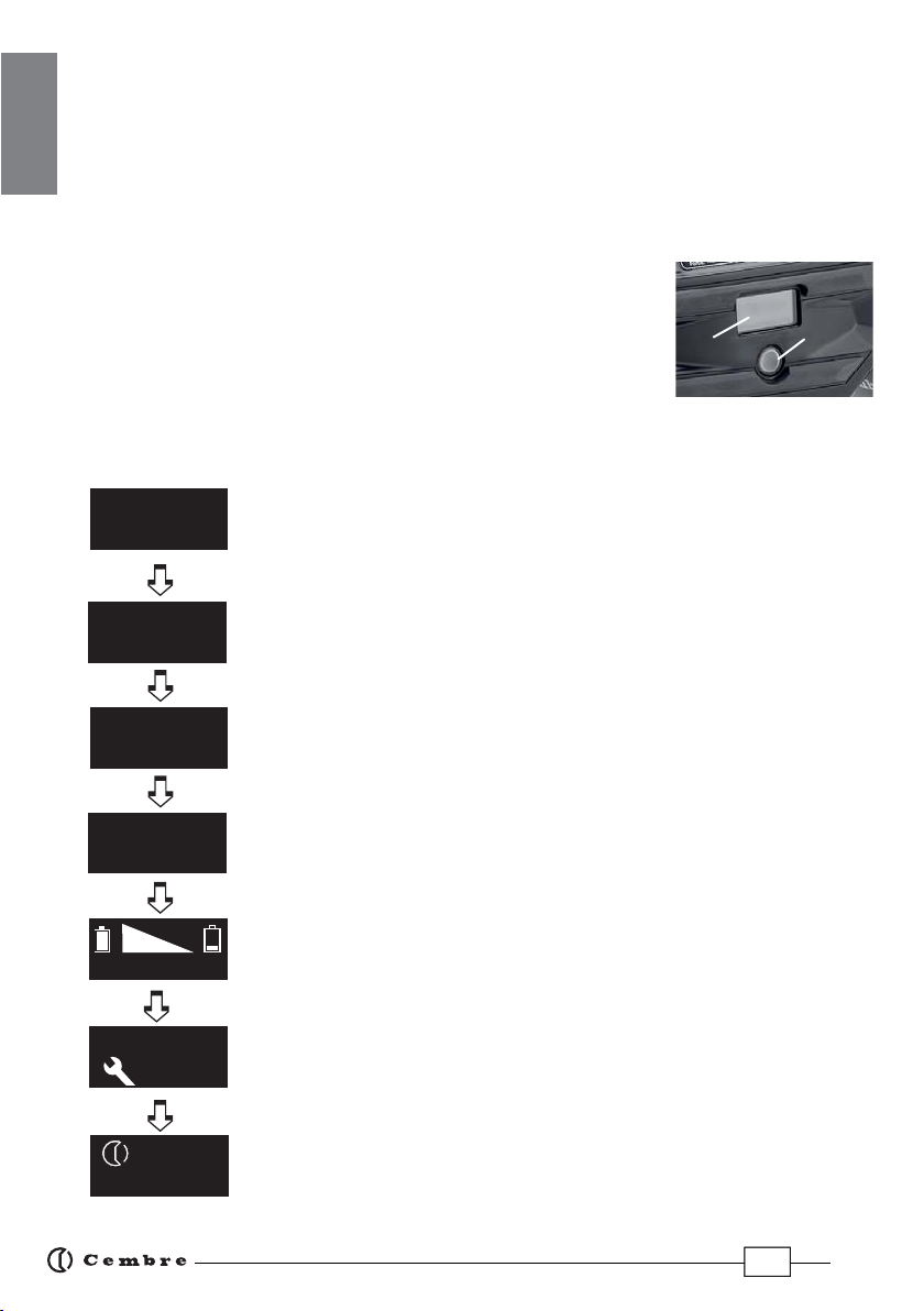
7. DISPLAY
The OLED display (8) switches on automatically when the operating or pressure release buttons are
pressed, and o after 60 seconds of non-operation.
The display shows:
- The main operational parameters of the tool processed by the circuit board, such as peak pres
sure or force reached.
- Information on the condition of the tool, such as the charge level, the battery temperature and
maintenance requirements.
- Any operational or procedural ERRORS.
Use the touch button (7) to navigate through the menu screens to
manage INFORMATION AND SELECTION:
7.1) INFORMATION SCREENS: display a pre determined parameter which will then
appear each time the tool is started and during the entire work cycle.
B1300
NR 15AA190
Fm= 125.2 kN
Fp = 94.5 kN
Fm= 14.07 ton
Fp = 10.61 ton
1000
-12000
3
BATTERY
Pm= 10037 psi
Pp = 7575 psi
Pm= 692 bar
Pp = 522.3 bar
Fm: Minimum set force, expressed in kN.
Fp: Peak force reached, expressed in kN,
(screen as factory setting)
Fm: Minimum set force, expressed in USA sh. tons.
Fp: Peak force reached, expressed in USA sh. tons.
Pm: Minimum set pressure, expressed in bar.
Pp: Peak pressure reached, expressed in bar.
Pm: Minimum set pressure, expressed in psi.
Pp: Peak pressure reached, expressed in in psi.
Battery charge level.
No. of cycles performed.
No. of cycles before scheduled recommended maintenance.
Cembre logo, tool model.
Tool serial no
87
15
FRANÇAIS
To make a selected screen operational and appear at each start-up of the
tool, operate the touch button for at least 3 seconds; a continuous beep
will conrm the setting.
The capacitive menu selection button may not work if touched using
objects or when wearing gloves, therefore always operate it using a bare nger.
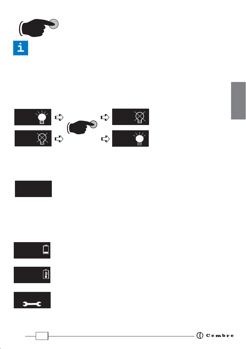
7.2) SELECTION SCREENS: control parameters that cannot be set as automatic upon start-up
of the tool, can be changed by operating the touch button:
Enabling/disabling the LED Worklights (factory setting LED ON)
When the screen is dis-
played, touch the button
for at least 3 seconds to
deactivate or reactivate op-
eration of the LED Worklights
during tool use;
a continuous beep will conrm
the setting.
Return to original factory settings / rmware version
When the‘RESET’screen is displayed, return the tool to its factory setting by operating the touch
button for at least 3 seconds; a beep will conrm the setting.
The RESET screen also shows the rmware version of the circuit board.
7.3) WARNINGS: these appear during operation and notify the operator of the status
of the tool:
LED
OFF
LED
ON
LED
OFF
3 SEC. LED
ON
LOW BATTERY: replace the battery.
NOTE: when the battery Vage falls below a minimum safety threshold, the tool
will not start; although it is still possible to end the work cycle in progress.
BATTERY TEMPERATURE HIGH: remove the battery and wait until it cools
down.
NO. OF CYCLES TO MAINTENANCE REACHED:
the tool continues to work however, it is recommended that it is sent to Cembre
for a complete overhaul (see § 9).
NOTE: this message, together with a beep, will reappear when the tool has been
idle for 30 seconds.
13001
3
BATTERY Ï
Ð
Ï
Ð
BATTERY
Ï
Ð
RESET
SW:S1J41405
3 SEC.
16
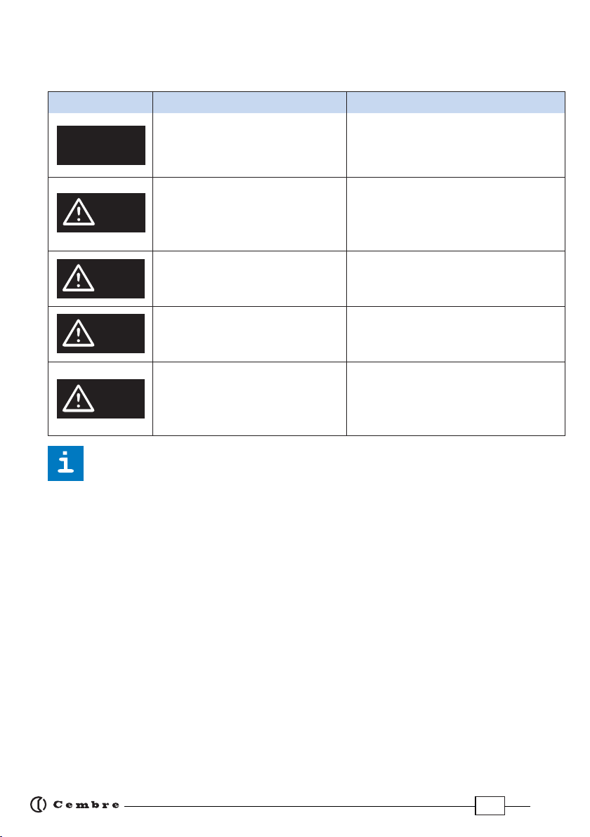
7.4) ERRORS: these appear during operation, combined with a beep and ashing LED Worklights,
to notify the operator of procedural or operational errors.
Message Error description Solution
ERROR
Ï
Ð
The pressure release button (2) was
pressedbeforethecontrolparameters
were reached (Force/Pressure).
Repeattheworkcycleandwaitforthemotor
to stop automatically.
001
Ï
Ð
Abnormal power consumption of the
motor for more than 3 seconds.
The tool stops.
Wait for the display to turn o (60 sec.) or
remove and re-insert the battery, then re-
start the tool.
If the error occurs frequently, contact
Cembre.
002
Ï
Ð
Output voltage of the pressure trans-
mitter is out of the pre-set range.
Repeat the work cycle; if the errors
reoccurs frequently, contact Cembre.
003
Ï
Ð
Failureto reach the set pressurewithin
30secondsof continuous operationof
the machine.
Repeat the work cycle; if the errors
reoccurs frequently, contact Cembre.
004
Ï
Ð
Overcharging of the battery with
protection tripping.
The tool stops.
Wait for the display to turn o (60 sec.) or
remove and re-insert the battery, then re-
start the tool.
If the error occurs frequently, contact
Cembre.
Errors are displayed for about 30 seconds before being reset, but will display repeatedly in
the event of permanent anomalies.
8. CONNECTION TO COMPUTER
The memory card integrated in the tool records operating data from 200.000 cycles for transfer via
the USB cable supplied.
To view and manage this data, go to www.cembre.com and register in the dedicated area, then
download the free Cembre software CEM_SWBT01.
Keeping the Firmware of the tool updated, via free of charge download from here, will optimise
the tool's performance.
9. RETURN TO Cembre FOR OVERHAUL
In the case of a breakdown, contact your local Agent who will advise you on the problem and give
you the necessary instructions on how to dispatch the tool to our nearest service Centre; if possible,
attach a copy of the Cembre Test Certicate supplied with the tool or, if no other references are
available, indicate the approximate purchase date and the tool serial number.

17
1.CARACTERISTIQUES GENERALES
B1300-UC
B1300-UCE B1300-UCT B1300-UCA
Domaine d'application: conçue pour le sertissage des connecteurs pour câbles
jusqu'à 400 mm2(800 MCM) et pour câbles
en aluminium jusqu'à 300 mm2(600 MCM).
Force nom. de sertissage kN (USA ton) 132 (14.84)
Force min. de sertissage
développée
kN (USA ton) 125,2 (14.07)
Pression min. de travail bar (psi) 692 (10037)
Dimensions (voir Fig. 6) mm (inches) 423 x 239 x 102,5 (16.6 x 9.4 x 4)
Poids avec batterie kg (lbs) 6,5 (14.3)
Moteur V DC 18
Température de fonction-
nement:
°C (°F) -15 à +50 (+5 à +122)
Huile recommandée: AGIP ARNICA 32 ou équivalents.
Avance rapide:
l’outil passe automatiquement de la vitesse rapide d’appro-
che des matrices à la vitesse lente de sertissage.
Sécurité valve de surpression.
Batterie rechargeable V / Ah / Wh 18 / 4.0 / 72
Type CB1840L (LI-Ion)
Poids kg (lbs) 0.66
Chargeur de batterie
ASC30-36
Alimentation
type EU
27044000
UK
27045000
AUS/NZ
27047000
USA/CAN
27046000
V / Hz 220 - 240 / 50 - 60 115 / 60
W85
Bruit aérien sonore (1)
LpA dB (A) 66,9
LpCPeak dB (C) 86,9
LWA dB (A) 74,9
Vibrations (2) m/s20.398 max.
(1) (Directive 2006/42/CE, annexe 1, point 1.7.4.2, lettre u)
LpA
= niveau de pression sonore continue équivalente pondérée A sur le poste de travail.
LpCPeak
= valeur de pression sonore instantanée pondérée C sur le poste de travail.
LWA
= niveau de puissance acoustique dégagée par la machine.
(2) (Directive 2006/42/CE, annexe 1, point 2.2.1.1)
Valeur quadratique moyenne pondérée en fréquence de l'accélération à laquelle sont exposés les membres supérieurs
pour chaque axe biodynamique de référence. Relevés réalisés suivant les indications des Normes UNI ENV 25349 et
UNI EN 28662 partie 1a, dans des conditions de service largement représentatives des conditions d'emploi normales.

18
FRANÇAIS
AVERTISSEMENT
Ne pas utiliser cet outil à des ns diérentes que celles prévues par le constructeur.
Restez bien attentif tout au long du travail, ne soyez pas distrait, ne perdez
pas l’équilibre pendant l'utilisation.
Avant d’entreprendre des travaux sur des équipements électriques, veuillez vous
assurer qu’aucun élément aux abords de la zone de travail n’est sous tension.
Dans le cas contraire, veuillez prendre les précautions nécessaires pour opérer
à proximité d’éléments sous tension, en conformité avec la norme EN50110-1.
Ne pas utiliser cet outil sur ou à côté de conducteurs sous tension, sans pro-
tection individuelle adéquate. la non observation de cette précaution
peut provoquer des lesions graves ou mortelles.
L’outil n’est pas conçu pour une utilisation en continu; après avoir effectué une
quantité de sertissages consécutifs à partir d’une batterie complètement
chargée, au moment du remplacement de la batterie, nous suggérons d’observer
une période d’arrêt pour permettre le refroidissement de l’outil.
Protéger l’outil de la pluie et de l’humidité. L’eau pourrait endommager l’outil et
la batterie, les outils hydro-électriques ne devraient pas être utilisés sous la pluie.
2.INSTRUCTIONS D'UTILISATION
IMPORTANT: Ne jamais mettre l’outil sous pression sans les matrices insérées,
cela pourrait endommager les sièges de la tête et du piston.
L' ensemble comprend (Voir Fig. 7 page 57):
– Outil hydraulique le sertissage.
– Adaptateur supérieur AU130-C .
– Batterie rechargeable Li-Ion (2 pcs).
– Chargeur de batterie (diérent en fonction de la version de l'outil).
– Bandoulière.
– Coret de rangement.
– Câble USB ( Voir § 8).
L’équipement standard de l’outil comprend l’adaptateur AU130-C avec lequel il peut recevoir
divers types de matrices (communes également aux autres outils Cembre de 130 kN) destinées au:
Sertissage hexagonal et circulaire sur câble cuivre, almélec, aluminium ou aluminium-acier.
Poinçonnage sur câble cuivre.
Avec les adaptateurs supérieurs types AU130-150, AU130-240 et inférieure AC130-P, l’outil peut
recevoir les:
Matrices de mise au rond UP 130-..., ramenant les câbles sectoraux à la forme circulaire.
Matrices coquille séries MV, MVC, MVM, MUA, réalisant un poinçonnage profond, matrice
fermée, sur câble aluminium.

19
FRANÇAIS
2.1) Mise en service
L’outil peut être transporté facilement grâce à sa poignée principale (12) et à la bandoulière
accrochée par deux anneaux (8).
Les positions de travail principales sont:
horizontale appuyé sur les pieds et ver-
ticale appuyé sur la batterie. Au-delà de
la poignée principale (12) dans la partie
inférieure est disponible une poignée
supplémentaire (6) qui permet une prise
sûre et équilibrée de façon de soutenir
l’outil à 2 mains.
Avant de commencer toute opération, contrôler
l’état de charge de la batterie (voir § 2.8) et, si nécessaire, la recharger
en suivant les instructions dans le manuel d’utilisation du chargeur de batteries.
Pour remplacer la batterie, il est plus facile de tenir l'outil com-
me indiqué sur la gure; appuyez sur le mécanisme de débloca-
ge (11) et enfoncez vers le bas la batterie en la décrochant.
Insérez la batterie chargée à partir du bas en la faisant coulisser
sur les guides jusqu’au blocage complet.
L’écranpermetd’acherlesparamètresopérationnelsdel’outil.
Pour personnaliser ces derniers, suivre les instructions au § 2.7.
Pour le type de connexion à réaliser suivre les instructions au
§ 4 ou 5.
2.2) Avance des matrices
Appuyer sur la gâchette de commande (1) pour mettre en mar-
che le groupe moteur pompe; les matrices commencent alors
à se rapprocher du connecteur.
La gâchette de commande relâchée, le moteur et l'avance des
matrices cessent immédiatement.
S
S'assurerquelesmatricessontbienpositionéessurlazone
à sertir, sinon desserer les matrices en suivant les instruc-
tions du § 2.4 et repositioner le connecteur.
2.3) Sertissage
En maintenant pressée la gâchette de commande (1), on main-
tient la rotation du moteur; le piston avance progressivement
jusqu'à ceque lesmatricesarriventen butéel'une contrel'autre.
L’outil s’arrêtera automatiquement dès qu’il aura atteint la pres-
sion de tarage.
Pour eectuer un bon sertissage, maintenir la gâchette de
commande(1)presséejusqu’àl’arrêtautomatiquedumoteur.
1
11
Batterie
6
12
8
8

20
FRANÇAIS
REMARQUE: Pour acher la force ou la pression en
temps réel, lors du cycle de travail, congurer les écrans
correspondants (voir § 7). En relâchant le bouton de
démarrage avant l’arrêt automatique du moteur, l’écran
achera les valeurs de pic de la force (Fp) et de la pression
(Pp) atteintes à ce moment.
Pour terminer l’opération, ré-appuyer sur la gâchette de commande jusqu’à l’arrêt automatique
du moteur; l’écran achera la force ou la pression maximale atteinte, suivie de l’inscription «OK»
indiquant que l’opération a été correctement eectuée.
Le message « ERROR » associé à l’avertisseur sonore ainsi que le
clignotement des LED indiquent que la procédure de sertissage n’a pas
été correctement eectuée en raison d’un arrêt anticipé du cycle de travail avant
d’avoiratteintlesparamètresréglés(force/pression)del’outil. Cemessaged’erreur
s’achelorsquel’opérateurappuiesur lagâchettededéblocagepressionaprèsquel’outilaitatteint
une pression > 100 bar. Dans ce cas, eectuer à nouveau le sertissage en maintenant la gâchette de
commande appuyée jusqu’à l’arrêt automatique du moteur. Pour terminer l’opération, ré-appuyer
sur la gâchette de commande jusqu’à l’arrêt automatique du moteur; l’écran achera la force ou la
pression maximale atteinte, suivie de «OK» indiquant que l’opération a été correctement eectuée.
2.4) Réouverture des matrices
En appuyant à fond sur la gâchette de déblocage (2), on provoque
le retour du piston et par conséquent l'ouverture des matrices.
2.5) Led
Lors de l’actionnement de l’outil, la zone de sertissage est éclairée
au moyen de deux LED haute luminosité qui s’éteignent automati-
quement à la n du cycle.
Pour désactiver les LED, suivre la procédure décrite au § 7.2.
2.6) Rotation de la tête
La tête de l'outil pivote de 180° par rapport au corps, permettant à l'utilisateur de travailler dans
la meilleure position.
Ne pas forcer la rotation de la tête, lorsque le circuit hydraulique est sous pression.
2.7) Touche tactile de type capacitif
Cettetoucheestsituéesousl’écranetpermetdesélectionnerlesdiérents
écrans (voir § 7); elle fonctionne uniquement lorsque l’écran est allumé
et il sut de l’eeurer à mains nues. L’utilisation de gants ou d’autres
objets risquerait de compromettre son activation.
Ne jamais appuyer avec force sur la touche tactile, il sut de l’eeurer avec un doigt, à
mains nues. La commande envoie l’impulsion dès le retrait du doigt.
ERROR
Ï
Ð
Fm= 125.2 kN
Fp= 102.3 kN
Pm= 692 bar
Pp = 565 bar
Fm= 125.2 kN
OK
Pm= 692 bar
OK
3 SEC.
2
This manual suits for next models
3
Table of contents
Languages:
Popular Power Tools manuals by other brands


Cleco
Cleco 20PTHD Series installation manual

Shrinkfast
Shrinkfast 998 UL Operating, field maintenance, and parts manual

DeWalt
DeWalt DCS391 instruction manual

Craftsman
Craftsman CMCF940 instruction manual

Central Pneumatic Professional
Central Pneumatic Professional 42248 Set up and operating instructions

Clarke
Clarke CHG1600 User instructions

Atlas Copco
Atlas Copco RT-25 Quick setup guide

Cornwell Tools
Cornwell Tools CAT1000MRRG quick start guide

Prebena
Prebena 11-L64 Original operating manual

F.F. Group
F.F. Group lD 710 PRO Original instructions

Amada
Amada Vipros 357 Queen User pre-installation guide

Parkside
Parkside PMFW 310 D2 Translation of the original instructions