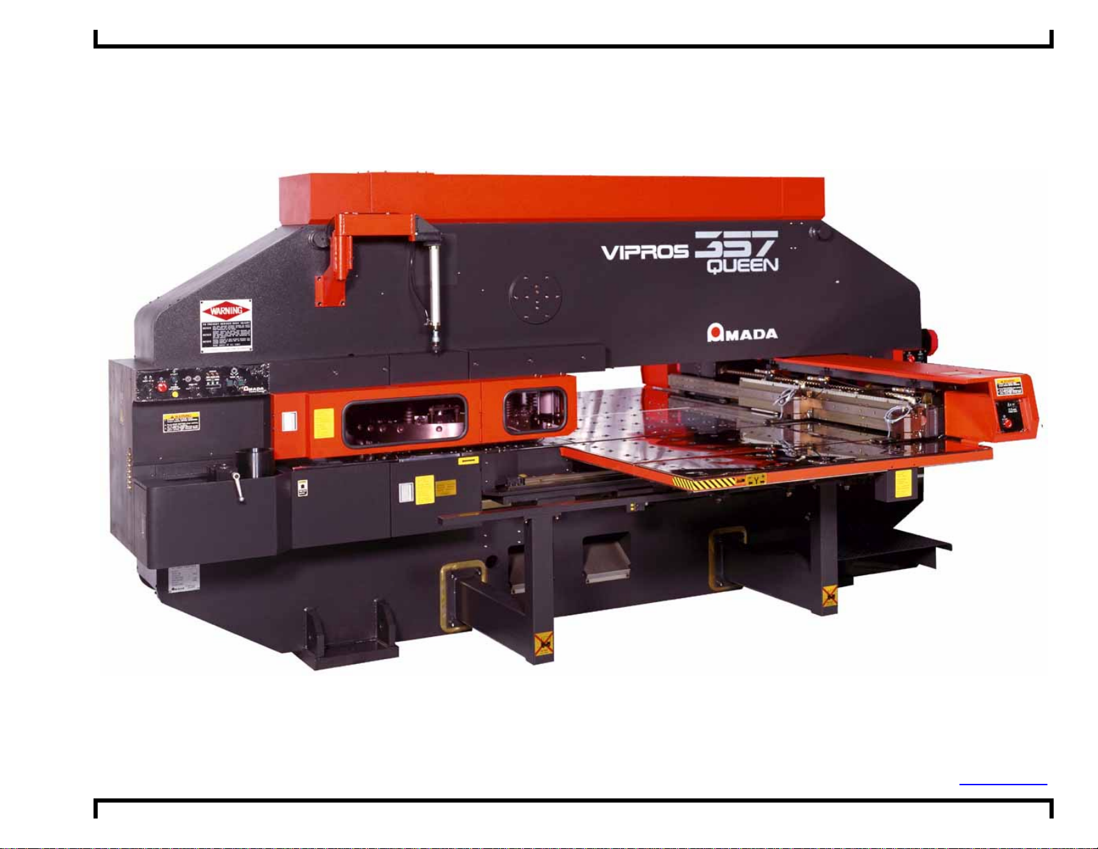
Vipros 357 Queen with Fanuc 18PC User Pre-installation Guide ©Amada America, Inc.
Print Date 01/24/2001 Revision 4.0 This document available on the World Wide Web at http://www.amada.com Page 3 of 37
Contents
Introduction ......................................................................................................................................................................................5
Specifications - Motion Package......................................................................................................................................................6
Specifications - Punching System....................................................................................................................................................7
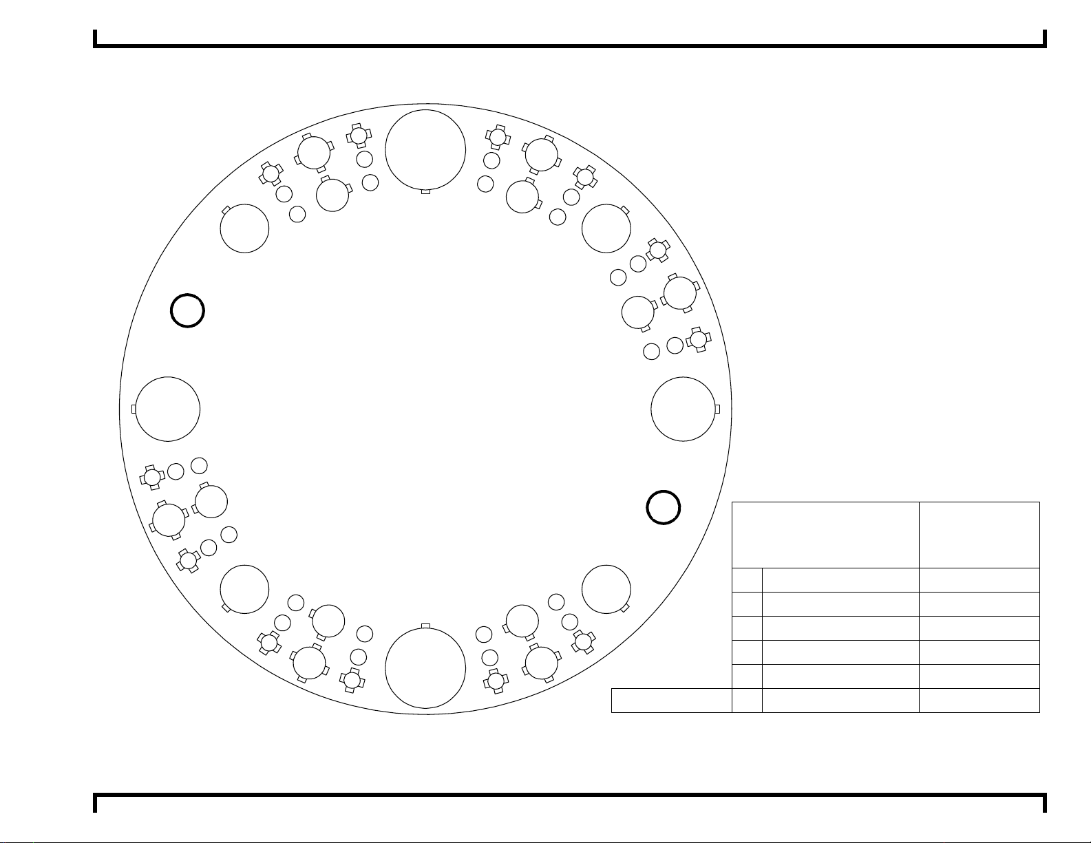
Turret Configuration - 58 Station - 2 Auto-Index.........................................................................................................................8
Specifications - Fanuc 18PC Controller ...........................................................................................................................................9
Specifications - Hydraulic Systems..................................................................................................................................................9
Power Hydraulic Numerical Control............................................................................................................................................9
Hydraulic Power Unit ..................................................................................................................................................................9
Supply Requirements - Electrical...................................................................................................................................................10
Optional Equipment..................................................................................................................................................................10
Installing the Electrical Power Supply.......................................................................................................................................11
Supply Requirements - Pneumatic.................................................................................................................................................12
Optional Equipment..................................................................................................................................................................12
Installing the Pneumatic Supply................................................................................................................................................12
Planning the Location of the Vipros 357 Queen.............................................................................................................................13
Moving the Vipros 357 Queen ..................................................................................................................................................13
Plan View - Vipros 357 Queen..................................................................................................................................................14
Plan View - Vipros 357 Queen with V357hs conveyor..............................................................................................................15
Plan View - Vipros 357 Queen with V357hs conveyor and MP1225 loader .............................................................................16
End View - Vipros 357 Queen...................................................................................................................................................17
Elevation View - Vipros 357 Queen..........................................................................................................................................18
SBC EX 5.5 Chiller.........................................................................................................................................................................19
SBC EX 5.5Chiller Placement...................................................................................................................................................19
Chiller Connections...................................................................................................................................................................20
Foundation Requirements..............................................................................................................................................................21
Foundation Anchoring Procedure ..................................................................................................................................................22
Foundation J-bolt Detail............................................................................................................................................................22
Plan View - Foundation Vipros 357 Queen...............................................................................................................................23
Elevation - Foundation Vipros 357 Queen................................................................................................................................23