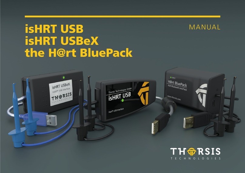
Thorsis Technologies isDNet USB User manual

isDNet USB MANUAL

2
CERTIFICATE OF CONFORMITY
We hereby declare, that the device indicated below in its design and
construction, is in conformity with the essential safety and health
requirements of the EC Directive 2014/30/EU.
CHANGES OR MODIFICATIONS NOT APPROVED BY
THORSIS TECHNOLOGIES VOID THE VALIDITY OF THE
DECLARATION.
Device type Order number
isDNet USB 11300-0101
Manufacturer
Thorsis Technologies GmbH
Oststr. 18
39114 Magdeburg
Germany
Magdeburg, 2018-08-28
Dipl.-Ing. Thorsten Szczepanski,
Managing director
STANDARDS USED: EN 61326-1:2013
according to EC Directive 2014/30/EU (electromagnetic compatibility) from February 26, 2014.

3
Table of Content
1. ISDNET USB . . . . . . . . . . . . . . . . . . . . . . . . . . . . . . . . . . . . . . . . . . . . . . . . . . . . . . . . . . . . . . . . . . . . . . . . . . . . . . . . . . . . . . . . . . . . . . . . . . . . . . .4
1.1 Technical details . . . . . . . . . . . . . . . . . . . . . . . . . . . . . . . . . . . . . . . . . . . . . . . . . . . . . . . . . . . . . . . . . . . . . . . . . . . . . . . . . . . . . . . . . . . . . . . . . . .5
1.2 Delivery content . . . . . . . . . . . . . . . . . . . . . . . . . . . . . . . . . . . . . . . . . . . . . . . . . . . . . . . . . . . . . . . . . . . . . . . . . . . . . . . . . . . . . . . . . . . . . . . . . . . 5
2. INSTALLATION AND COMMISSIONING . . . . . . . . . . . . . . . . . . . . . . . . . . . . . . . . . . . . . . . . . . . . . . . . . . . . . . . . . . . . . . . . . . . . . . . . . . . . . . . . .6
2.1 Installation of the driver software . . . . . . . . . . . . . . . . . . . . . . . . . . . . . . . . . . . . . . . . . . . . . . . . . . . . . . . . . . . . . . . . . . . . . . . . . . . . . . . . . . . .6
2.2 Installation of the hardware . . . . . . . . . . . . . . . . . . . . . . . . . . . . . . . . . . . . . . . . . . . . . . . . . . . . . . . . . . . . . . . . . . . . . . . . . . . . . . . . . . . . . . . . .7
2.2.1 Channel assignment. . . . . . . . . . . . . . . . . . . . . . . . . . . . . . . . . . . . . . . . . . . . . . . . . . . . . . . . . . . . . . . . . . . . . . . . . . . . . . . . . . . . . . . . . .7
2.2.2 LED display . . . . . . . . . . . . . . . . . . . . . . . . . . . . . . . . . . . . . . . . . . . . . . . . . . . . . . . . . . . . . . . . . . . . . . . . . . . . . . . . . . . . . . . . . . . . . . . . .8
2.3 Configuration and commissioning . . . . . . . . . . . . . . . . . . . . . . . . . . . . . . . . . . . . . . . . . . . . . . . . . . . . . . . . . . . . . . . . . . . . . . . . . . . . . . . . . . . .9
2.3.1 Add a device . . . . . . . . . . . . . . . . . . . . . . . . . . . . . . . . . . . . . . . . . . . . . . . . . . . . . . . . . . . . . . . . . . . . . . . . . . . . . . . . . . . . . . . . . . . . . . . 10
2.3.2 Add an Empty-Slot . . . . . . . . . . . . . . . . . . . . . . . . . . . . . . . . . . . . . . . . . . . . . . . . . . . . . . . . . . . . . . . . . . . . . . . . . . . . . . . . . . . . . . . . . . 11
2.3.3 Removal of a device . . . . . . . . . . . . . . . . . . . . . . . . . . . . . . . . . . . . . . . . . . . . . . . . . . . . . . . . . . . . . . . . . . . . . . . . . . . . . . . . . . . . . . . . . 12
2.4 Test Software: isDNet Demo . . . . . . . . . . . . . . . . . . . . . . . . . . . . . . . . . . . . . . . . . . . . . . . . . . . . . . . . . . . . . . . . . . . . . . . . . . . . . . . . . . . . . . . . 12
3. DOCUMENT HISTORY . . . . . . . . . . . . . . . . . . . . . . . . . . . . . . . . . . . . . . . . . . . . . . . . . . . . . . . . . . . . . . . . . . . . . . . . . . . . . . . . . . . . . . . . . . . . . . 13

4
1. isDNet USB
The Interface isDNet USB provides a communication link between a
desktop computer or PC notebook and a Device Network. The PC can
be connected with the Device Network using the USB plug & play fea-
tures. Realtime data of the field devices are available for operational
areas, e.g. mobile data aquisition and parameterization.
The interface is not dependent on external power supplies. The pro-
cessor and its periphery are powered by the USB bus. The transceiver
is galvanic decoupled, its supply results from the DeviceNet Bus.
The interface supports the DeviceNet Standard Version 2.0.
Its connector cable comes with a 5-pin connector. The DeviceNet Stack
works alternative or in parallel as Master (and IO scanner) or Slave.
The scanner allows a dynamic change of the slave list, which means
while the DeviceNet is working slave devices can be added to or
eliminated from the scan list. The cyclic time of the the scan can be
set as required by the system. The „Explicit Messaging“ funcionality
is performed employing asynchronous command and event queues.
Thus any data lengths can be transmitted.

5
1.1 Technical details
1.2 Delivery content
DeviceNet-USB-Interface „isDNet USB“, Driver, configuration and test software as well as
documentation in German and English on a memory stick.
Interface isDNet USB
Connector DeviceNet (COMBICON 5-polig) USB 2.0
Controller Asic SJA1000 CY7C68014A
Transmission rate 125 kbit/s, 250 kbit/s, 500 kbit/s Full Speed: 12 Mbit/s, High Speed: 480 Mbit/s
Driver software Windows 7,8 & 10
Available software DNet CommDTM (FDT)

6
2. Installation and commissioning
2.1 Installation of the driver software
The driver software must be installed before connecting the device.
Otherwise, the operating system can not find the interface to the associated driver.
The driver software package isDNet Multidriver contains a Dynamic Link Library (DLL) which allows the access to the
firmware under the operating systems Windows 7, 8, 10. The actual operating system is detected
automatically by the driver DLL.
The configuration of the interface can be done with the configuration software isDNet Driver Configurator which
is installed into the Thorsis directory of the Start Menu.
Installation process:
• Login as administrator.
• Connect the memory stick.
• The setup starts with an autoroutine; proceed according to the instructions displayed on the screen.
Should Autorun be disabled on your machine, run the setup.exe on the Memory-Stick.
• The installation is done in the standard program directory of the target machine under
C:\Program Files\Thorsis Technologies\isDNet Driver

7
2.2 Installation of the hardware
The Interface can be connected to the DeviceNet network with its
COMBICON connector directly.
Use a USB cable to connect the interface to a PC / notebook.
2.2.1 Pin assignment
The contacts of the 5-pin COMBICON connector are assigned as follows:
Pin 1: V-(OV), black
PIN 2: CAN_LOW, blue
Pin 3: drain
Pin 4: CAN_HIGH, wihte
Pin 5: V+(24V), red

8
Two LEDs (see figure) enable reading of operating states directly on
the device.
2.2.2 LED display
The Module Status LED (MS) displays the status of the device:
The network status (NS) LED gives information about the status of
the communication:
LED meaning
off device is not in use
green normal operating status
red/green flashing self test is being completed
red error, device can be out of order
At beginning of the initialisation both LEDs are running through all
their possible states of lightning:
(MS=green, MS=red, NS=green, MS= red).
This allows to check the LEDs funcionality.
LED meaning
off device is offline
green flashing online, no connections are active
green online, there is at least one connection
red flashing at least one connection is at timed-out
status
red MAC-ID-conflict or connection to the
bus is being disturbed

9
2.3 Configuration and Commissioning
The isDNet Driver Configurator is available to simplify the config-
uration of the DeviceNet interface isDNet USB. The program is
installed in the start menu.
Using this program, the DeviceNet interface and its serial number
can easily be added to an existing configuration. The configu-
ration program can also detect the serial numbers of connected
interfaces.
Each device is assigned a specific number that can be used to ad-
dress it. Due to the possibility of inserting empty devices, devices
can be assigned to any device number that does not have to be
numbered consecutively.

10
Please press the button “Add“ and select the device type. Then
enter all necessary settings.
The isDNet USB device has a serial number for a unique identifi-
cation. The number is printed on a label located at the bottom of
the Interface and is also stored in the device.
The configuration software offers the possibility to search auto-
matically for all attached devices and to detect their serial numbers.
If you work under Windows 7, 8 or 10, just finish your settings
with OK. All settings are saved.
2. 3.1 Add a device

11
The empty device does not contain any resources. It serves as a
substitute for device numbers not yet assigned. Using this devices
enables a free enumeration of devices by inserting empty devices
between existing ones.
For example, if you want to assign the number 3 to a device and
there is no device with the number 2, simply add an empty slot
behind the device 1.
2.3.2 Add an Empty Slot

12
Mark the device you wish to remove and press the button Remove.
You can then remove the device from the USB port.
The correct operation of the isDNet interface can be checked with the isDNet Demo
test application that is included in the driver installation package.
The test tool is installed in the Thorsis folder of the start menu.
The following functions are provided by the application:
• Select the configured adapter
• Baudrate settings
• Transmisson of messages
• Display of received messages
2.3.3 Removal of a device
2.4 Test Software: isDNet Demo

13
3. Document History
version date description
1.0 01.06.2012 initial version
1.1 05.09.2017 new images
1.2 14.05.2020 new graphics, images and texts
© last change 14. Mai 2020
Thorsis Technologies GmbH
Oststr. 18
39114 Magdeburg
Deutschland
Tel +49 391 544 563-1000
Fax +49 391 544 563-9099
info@thorsis.com
www.thorsis.com
Other manuals for isDNet USB
1
Table of contents
Other Thorsis Technologies USB Interface manuals