Thrush Aircraft S2RHG-T65 TURBO THRUSH User manual

THRUSH AIRCRAFT, INC – MODEL S2RHG-T65 TURBO THRUSH
AIRCRAFT MAINTENANCE MANUAL
Effective: 09/16/05 i
AIRCRAFT MAINTENANCE MANUAL
SINGLE AND DUAL COCKPIT
Model S2RHG – T65
Serial Numbers T65HG – 011 & Up, T65HG – 013 DC & Up
Manual Number: T65HG-2
Issued May 5, 2004
Revised September 16, 2005
Manufacturer’s Serial Number: ____________________________________________
Registration Number: ____________________________________________________
Thrush Aircraft Inc.
P. O. Box 3149
300 Old Pretoria Road
Albany, GA 31706
Telephone: 229-883-1440
Fax: 229-436-4856

THRUSH AIRCRAFT, INC – MODEL S2RHG-T65 TURBO THRUSH
AIRCRAFT MAINTENANCE MANUAL
LOG of PAGES
ii Effective: 09/16/05
INTRODUCTION
Page Date
i .......................................... 09/16/05
ii .......................................... 09/16/05
iii .......................................... 09/16/05
iv .......................................... 09/16/05
v .......................................... 05/25/05
vi .......................................... 09/16/05
vii .......................................... 09/16/05
viii .......................................... 09/16/05
SECTION 1
GENERAL
INFORMATION
Page Date
1 .......................................... 09/16/05
2 .......................................... 09/16/05
3 .......................................... 09/16/05
4 .......................................... 05/05/04
5 .......................................... 09/16/05
6 .......................................... 05/05/04
7 .......................................... 09/16/05
8 .......................................... 05/05/04
9 .......................................... 05/05/04
SECTION 2
SERVICING &
INSPECTION
Page Date
1 .......................................... 09/16/05
2 .......................................... 09/16/05
3 .......................................... 05/05/04
4 .......................................... 05/05/04
5 .......................................... 05/05/04
6 .......................................... 05/05/04
7 .......................................... 05/05/04
8 .......................................... 09/16/05
9 .......................................... 05/05/04
10 .......................................... 05/05/04
11 .......................................... 05/05/04
12 .......................................... 09/16/05
13 .......................................... 09/16/05
14 .......................................... 05/05/04
15 .......................................... 05/05/04
16 .......................................... 05/05/04
17 .......................................... 05/05/04
18 .......................................... 05/05/04
19 .......................................... 05/25/05
20 .......................................... 05/25/05
21 .......................................... 05/05/04
22 .......................................... 05/25/05
23 .......................................... 05/25/05
24 .......................................... 05/05/04
25 .......................................... 05/05/04
26 .......................................... 05/25/05
27 .......................................... 05/05/04
28 .......................................... 05/05/04
29 .......................................... 05/05/04
SECTION 2
SERVICING &
INSPECTION
(Continued)
Page Date
30 .......................................... 05/05/04
31 .......................................... 05/05/04
32 .......................................... 05/05/04
33 .......................................... 05/05/04
34 .......................................... 05/05/04
35 .......................................... 05/05/04
36 .......................................... 05/05/04
37 .......................................... 05/05/04
38 .......................................... 05/05/04
39 .......................................... 05/05/04
40 .......................................... 05/05/04
41 .......................................... 05/05/04
42 .......................................... 05/05/04
43 .......................................... 05/05/04
44 .......................................... 09/16/05
45 .......................................... 05/05/04
SECTION 3
HYDRAULICS
Page Date
1 .......................................... 05/05/04
2 .......................................... 05/05/04
SECTION 4
POWERPLANT &
PROPELLER
Page Date
1 .......................................... 09/16/05
2 .......................................... 09/16/05
3 .......................................... 05/05/04
4 .......................................... 05/05/04
5 .......................................... 05/05/04
6 .......................................... 05/05/04
7 .......................................... 05/05/04
8 .......................................... 05/05/04
9 .......................................... 05/05/04
10 .......................................... 05/05/04
11 .......................................... 05/05/04
12 .......................................... 05/05/04
13 .......................................... 05/05/04
14 .......................................... 05/05/04
15 .......................................... 05/05/04
16 .......................................... 05/05/04
17 .......................................... 05/05/04
18 .......................................... 05/05/04
19 .......................................... 05/05/04
20 .......................................... 05/05/04
21 .......................................... 05/05/04
22 .......................................... 05/05/04
23 .......................................... 05/05/04
24 .......................................... 05/05/04
25 .......................................... 09/16/05
26 .......................................... 09/16/05

THRUSH AIRCRAFT, INC – MODEL S2RHG-T65 TURBO THRUSH
AIRCRAFT MAINTENANCE MANUAL
LOG of PAGES
Effective: 09/16/05 iii
SECTION 4
POWERPLANT &
PROPELLER
(Continued)
Page Date
27 .......................................... 09/16/05
28 .......................................... 05/05/04
29 .......................................... 09/16/05
30 .......................................... 05/05/04
31 .......................................... 05/05/04
32 .......................................... 05/05/04
33 .......................................... 05/05/04
34 .......................................... 05/05/04
35 .......................................... 05/05/04
36 .......................................... 05/05/04
37 .......................................... 05/05/04
38 .......................................... 05/05/04
39 .......................................... 05/05/04
40 .......................................... 05/05/04
SECTION 5
FUEL SYSTEM
Page .......................................... Date
1 .......................................... 09/16/05
2 .......................................... 09/16/05
3 .......................................... 09/16/05
4 .......................................... 05/05/04
5 .......................................... 09/16/05
6 .......................................... 05/05/04
7 .......................................... 05/05/04
8 .......................................... 05/25/05
9 .......................................... 05/05/04
10 .......................................... 05/25/05
11 .......................................... 05/05/04
12 .......................................... 09/16/05
13 .......................................... 09/16/05
14 .......................................... 05/05/04
15 .......................................... 05/05/04
16 .......................................... 09/16/05
SECTION 6
LANDING GEAR,
WHEELS & BRAKES
Page Date
1 .......................................... 09/16/05
2 .......................................... 09/16/05
3 .......................................... 05/05/04
4 .......................................... 09/16/05
5 .......................................... 09/16/05
6 .......................................... 09/16/05
7 .......................................... 05/25/05
8 .......................................... 05/25/05
9 .......................................... 05/25/05
10 .......................................... 05/05/04
11 .......................................... 05/05/04
12 .......................................... 05/25/05
13 .......................................... 05/25/05
14 .......................................... 05/25/05
SECTION 6
LANDING GEAR,
WHEELS & BRAKES
(Continued)
Page Date
15 .......................................... 05/25/05
16 .......................................... 05/05/04
17 .......................................... 05/05/04
18 .......................................... 05/05/04
19 .......................................... 05/05/04
20 .......................................... 05/05/04
21 .......................................... 05/05/04
22 .......................................... 09/16/05
23 .......................................... 05/25/05
24 .......................................... 05/25/05
25 .......................................... 05/25/05
26 .......................................... 05/25/05
27 .......................................... 05/25/05
28 .......................................... 05/25/05
29 .......................................... 05/25/05
30 .......................................... 09/16/05
31 .......................................... 09/16/05
SECTION 7
FLIGHT CONTROLS
Page Date
1 .......................................... 09/16/05
2 .......................................... 09/16/05
3 .......................................... 09/16/05
4 .......................................... 05/05/04
5 .......................................... 05/05/04
6 .......................................... 05/05/04
7 .......................................... 05/05/04
8 .......................................... 05/05/04
9 .......................................... 05/05/04
10 .......................................... 05/05/04
11 .......................................... 05/05/04
12 .......................................... 09/16/05
13 .......................................... 09/16/05
14 .......................................... 09/16/05
15 .......................................... 09/16/05
16 .......................................... 05/05/04
17 .......................................... 05/05/04
18 .......................................... 05/05/04
19 .......................................... 05/05/04
20 .......................................... 05/05/04
21 .......................................... 05/05/04
22 .......................................... 05/05/04
23 .......................................... 05/05/04
24 .......................................... 05/05/04
25 .......................................... 05/05/04
26 .......................................... 09/16/05
27 .......................................... 09/16/05
28 .......................................... 09/16/05
29 .......................................... 09/16/05
30 .......................................... 09/16/05
31 .......................................... 09/16/05
32 .......................................... 09/16/05

THRUSH AIRCRAFT, INC – MODEL S2RHG-T65 TURBO THRUSH
AIRCRAFT MAINTENANCE MANUAL
LOG of PAGES
iv Effective: 09/16/05
SECTION 7
FLIGHT CONTROLS
Page (Continued) Date
33 .......................................... 09/16/05
34 .......................................... 09/16/05
35 .......................................... 09/16/05
36 .......................................... 09/16/05
37 .......................................... 09/16/05
38 .......................................... 09/16/05
39 .......................................... 09/16/05
40 .......................................... 09/16/05
41 .......................................... 05/05/04
42 .......................................... 05/05/04
SECTION 8
INSTRUMENTS
Page Date
1 .......................................... 09/16/05
2 .......................................... 05/05/04
3 .......................................... 05/05/04
4 .......................................... 05/05/04
5 .......................................... 05/05/04
6 .......................................... 05/05/04
7 .......................................... 05/05/04
8 .......................................... 05/05/04
9 .......................................... 05/05/04
10 .......................................... 05/05/04
11 .......................................... 05/05/04
12 .......................................... 05/05/04
13 .......................................... 05/05/04
14 .......................................... 09/16/05
15 .......................................... 09/16/05
16 .......................................... 05/05/04
17 .......................................... 05/05/04
SECTION 9
DISPERSAL SYSTEMS
Page Date
1 .......................................... 09/16/05
2 .......................................... 05/05/04
3 .......................................... 05/05/04
4 .......................................... 05/05/04
5 .......................................... 05/05/04
6 .......................................... 05/05/04
7 .......................................... 05/05/04
8 .......................................... 05/05/04
9 .......................................... 05/05/04
10 .......................................... 05/05/04
SECTION 10
ELECTRICAL
SYSTEM
Page Date
1 .......................................... 09/16/05
2 .......................................... 09/16/05
3 .......................................... 05/05/04
4 .......................................... 05/05/04
5 .......................................... 05/05/04
SECTION 10
ELECTRICAL
SYSTEM
Page (Continued) Date
6 .......................................... 05/05/04
7 .......................................... 05/05/04
8 .......................................... 05/05/04
9 .......................................... 05/05/04
10 .......................................... 05/05/04
11 .......................................... 09/16/05
12 .......................................... 09/16/05
13 .......................................... 09/16/05
14 .......................................... 09/16/05
15 .......................................... 09/16/05
16 .......................................... 09/16/05
17 .......................................... 09/16/05
18 .......................................... 09/16/05
19 .......................................... 09/16/05
21 .......................................... 09/16/05
22 .......................................... 09/16/05
23 .......................................... 09/16/05
24 .......................................... 09/16/05
25 .......................................... 09/16/05
26 .......................................... 09/16/05
27 .......................................... 09/16/05
28 .......................................... 09/16/05
29 .......................................... 09/16/05
30 .......................................... 09/16/05
31 .......................................... 09/16/05
32 .......................................... 09/16/05
33 .......................................... 09/16/05
34 .......................................... 09/16/05
35 .......................................... 09/16/05
36 .......................................... 09/16/05
37 .......................................... 09/16/05
38 .......................................... 09/16/05
39 .......................................... 09/16/05
40 .......................................... 09/16/05
41 .......................................... 09/16/05
42 .......................................... 09/16/05
43 .......................................... 09/16/05
44 .......................................... 09/16/05
45 .......................................... 09/16/05
46 .......................................... 09/16/05
47 .......................................... 09/16/05
47 .......................................... 09/16/05
48 .......................................... 09/16/05
49 .......................................... 09/16/05
50 .......................................... 09/16/05
SECTION 11
AIRWORTHINESS
LIMITATIONS
Page Date
1 .......................................... 05/05/04
2 .......................................... 05/05/04

THRUSH AIRCRAFT, INC – MODEL S2RHG-T65 TURBO THRUSH
AIRCRAFT MAINTENANCE MANUAL
Effective: 05/25/05 v
LOG OF REVISIONS
Rev.
No. FAA
Acceptance Date Section Pages Description of Revision FAA
Accepted
NEW JUL 26, 2004 ALL ALL NEW BOOK C. Lorenzen
R1 05/25/05
Prelude
1
2
4
5
6
7
i
ii, iii, iv
vi
6
24
25
27,28
32
52
32, 36
35
9
11
1, 3, 4, 5,
6, 6a
10, 11, 12,
12a, 12b
19, 19a,
20, 20a,
22, 22a
13, 14
39
Revise cover.
Revise log of pages.
Revise log of Revisions.
Typo, toe instead of to.
Change inspection procedure.
Change inspection intervals for FCU
vent.
Added more detailed inspection for tail
gear.
Change inspection interval for control
stick bolt inspection.
P/N typo, MS21044N instead of
MS20144N, added MS21046 and
MS21245.
Propeller blade typo, changed to
M10876AS instead of AN.
Typo, -65AR instead of-67AR.
P/N typo, should be CS3204 instead of
CS3024.
Change caution pressure.
Updated tail gear servicing information.
Added servicing information on metallic
brakes.
Updated and added tail gear and brake
illustrations.
Reword sentence, change vertical fin
installation procedure.
P/N typo, changed to AN960-716
washer, MS21042-7 Nut.
C. Lorenzen

THRUSH AIRCRAFT, INC – MODEL S2RHG-T65 TURBO THRUSH
AIRCRAFT MAINTENANCE MANUAL
vi Effective: 09/16/05
LOG OF REVISIONS
Rev.
No. FAA
Acceptance Date Section Pages Description of Revision FAA
Accepted
R2
Forward
Section
1
Section
2
Section
4
Section
5
Section
6
i
ii-iv
vi & vii
viii
1
2
3
5
6
1&2
8
12
13
44
1&2
3
25
26
27
29
1
2
3
5
12
13
16
1&2
4
5
6
15 & 16
22
30 & 31
Revised Cover Sheet
Revised Log of Pages
Added R2 Log of Revisions
Added paragraph
Updated Table of Contents
Added phone ext., added dual
cockpit aft CG limit
Updated wing area for extension
Reworded Cockpit to reflect dual
cockpit. Corrected wing tank
location
Corrected wheel size
Updated Table of Contents
Added P & W Service phone #
Corrected fuel specifications,
improved description of fuel drains
Added Caution
Revised Torque Chart
Updated Table of Contents
Added dual cockpit engine
statement
Clarified wording
Corrected figure reference
Clarified chart reference
Corrected max continuous HP
Updated Table of Contents
Deleted redundant wording,
clarified fuel gauge operation
Added specific drain instructions
Re-formatted chart for clarity
Added Figure reference
Changed Note to Caution
Added Figure
Updated Table of Contents
Changed sentence to Warning
Expanded instructions in H. & B.
Added Warning to C.
Added instructions in K.
Added C., sealing instructions
Consolidated Brake Lining
Conditioning Procedures
Updated Figure 6-1
Added new Figures

THRUSH AIRCRAFT INC
MODEL S2RHG-T65 TURBO THRUSH
AIRPLANE MAINTENANCE MANUAL
Effective: 09/16/05 vii
Rev.
No. FAA
Acceptance Date Section Pages Description of Revision FAA
Accepted
R2
(Cont’d)
Section
7
Section
8
Section
9
Section
10
1&2
9
12
13
14 & 15
26 – 40
1
14 & 15
1 & 2
1 & 2
11-50
Updated Table of Contents
Deleted unnecessary sentence
Corrected torque values
Added rigging tolerance
Corrected/clarified splice fitting
removal instructions
Re-ordered Figures
Updated Table of Contents
Noted these instrument marking
charts not applicable to dual cockpit
Updated Table of Contents
Updated Table of Contents
Updated electrical diagrams

THRUSH AIRCRAFT, INC – MODEL S2RHG-T65 TURBO THRUSH
AIRCRAFT MAINTENANCE MANUAL
viii Effective: 09/16/05
INTRODUCTION
This publication provides information for the Thrush Aircraft, Inc. Model S2RHG-T65
Turbo Thrush Aircraft. Installations or equipment will vary from model to model due to
the wide range of optional equipment. The information contained within this manual is
based on data available at the time of publication and will be kept current by changes or
service publications.
This manual contains information on aircraft systems and operating procedures required
for safe and effective maintenance. It shall not, however, be used as a substitute for
sound judgment.
In this manual:
*** WARNING *** Indicates a strong possibility of severe personal injury or loss
of life if instructions are not followed.
** CAUTION ** Indicates a possibility of personal injury or equipment
damage if instructions are not followed.
* NOTE * Gives helpful information.
** CAUTION **
Detailed descriptions of standard workshop procedures,
safety principles and service operations are NOT included in
this manual. Please note that this manual DOES contain
warnings and cautions against some specific service
methods which could cause PERSONAL INJURY or could
damage an aircraft or MAKE IT UNSAFE. Please
understand that these warnings cannot cover all conceivable
ways in which service, whether or not recommended by
Thrush Aircraft Inc., might be done or of the possible
hazardous consequences of each conceivable way, nor
could Thrush Aircraft Inc. investigate all such ways. Anyone
using service procedures or tools, whether or not
recommended by Thrush Aircraft Inc., must satisfy himself
thoroughly that neither personal safety nor aircraft safety will
be jeopardized.
Changes to this manual accomplished under the latest revision are marked with a solid
vertical line next to the change in the page margin. Formatting changes, minor wording
changes and correction of minor typographical errors are not marked as changes. If the
page is new or completely revised, only the effective date will be updated.
All information contained in this manual is based on the latest product information
available at the time of printing. We reserve the right to make changes at any time
without notice.

THRUSH AIRCRAFT, INC – MODEL S2RHG-T65 TURBO THRUSH
AIRCRAFT MAINTENANCE MANUAL
Effective: 9/16/05 1-1
SECTION 1
GENERAL INFORMATION
TABLE OF CONTENTS
GENERAL DESCRIPTION.............................................................................................2
CONTACT INFORMATION..................................................................................2
PRINCIPAL DIMENSIONS ............................................................................................. 2
GENERAL..................................................................................................................2
WING.........................................................................................................................2
HORIZONTAL STABILIZER AND ELEVATORS .......................................................3
VERTICAL STABILIZER AND RUDDER...................................................................3
AREAS.......................................................................................................................3
SUPPLIER FURNISHED COMPONENT MANUALS.................................................3
AIRCRAFT STRUCTURE...............................................................................................4
FUSELAGE................................................................................................................4
WING.........................................................................................................................4
EMPENNAGE............................................................................................................4
COCKPIT...................................................................................................................5
AIRCRAFT SYSTEMS....................................................................................................5
HYDRAULIC SYSTEMS............................................................................................5
POWER PLANT & PROPELLER...............................................................................5
FUEL SYSTEM..........................................................................................................5
LANDING GEAR, WHEELS & BRAKES....................................................................7
FLIGHT CONTROLS.................................................................................................7
INSTRUMENTS.........................................................................................................7
ELECTRICAL SYSTEM.............................................................................................7
AIRCRAFT WEIGHT & BALANCE.............................................................................7
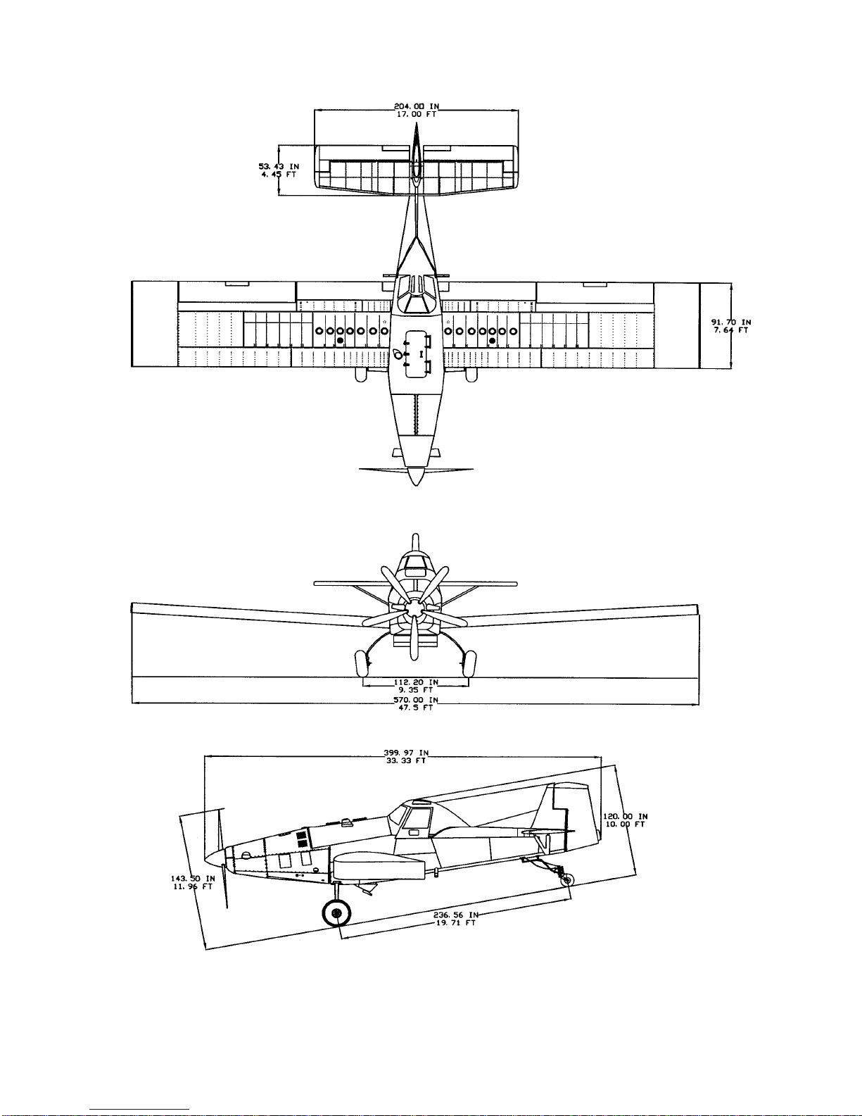
Figure 1-1: Aircraft 3-view...............................................................................8
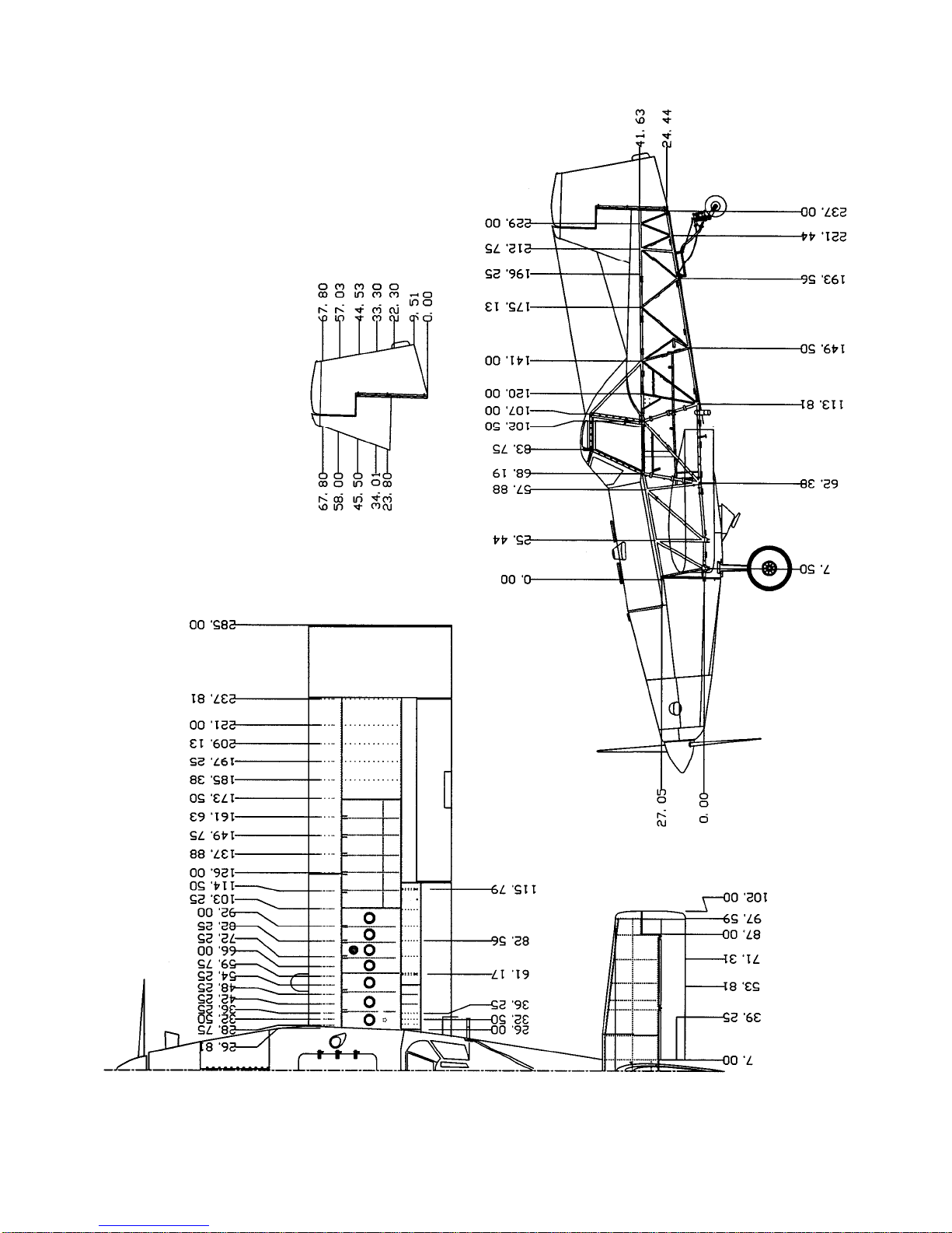
Figure 1-2: Aircraft Stations.............................................................................9
THRUSH AIRCRAFT, INC – MODEL S2RHG-T65 TURBO THRUSH
AIRCRAFT MAINTENANCE MANUAL
1-2 Effective: 9/16/05
GENERAL DESCRIPTION
The Thrush Aircraft Inc Turbo Thrush is designed especially for agricultural flying. It is a
monoplane featuring a full cantilever low wing and all metal construction. The design and
construction of the airframe components assure all structural integrity, flight safety, and
minimum maintenance requirements. The Turbo Thrush is designed for the highest crash
load factors in the industry. Safety and reliability of operation and maximum pilot crash
protection are proven and effective features of the design. The high strength overturn
structure is a proven design. The fuselage and overturn structure, constructed throughout
of chrome-moly steel tubing, is immensely strong in the cockpit area.
CONTACT INFORMATION
For further information related to this manual, please contact our Product Support
Manager at(229) 883-1440 extension 524.
PRINCIPAL DIMENSIONS
GENERAL
Wing Span Extended Tip 47.5 feet
Overall Length 33.33 feet
Height To Top Of Canopy 10.0 feet
Main Gear Tread 9.35 feet
Main Gear To Tail Wheel 19.71 feet
WING
Type Full Cantilever
Airfoil Section NACA 4412
Dihedral 3.50 Degrees
C. G. Range (See Airplane Flight Manual for pertinent data)
Forward Limit
Forward Limit at 7600 pounds and below is
22.5 inches aft of datum.
Forward Limit at 10500 pounds is 26 inches
aft of datum with straight line variations to
7600 pounds at 22.5 inches.
Aft Limit 29.0 Inches Aft Of Datum
28.0 inches for dual cockpit
Datum Datum Is The Leading Edge Of The Wing.
Aileron Travel
-Up 21 Degrees ±1 Degree
-Down 17 Degrees ±1 Degree
Flap Travel Down 15 Degrees ±1 Degree

THRUSH AIRCRAFT, INC – MODEL S2RHG-T65 TURBO THRUSH
AIRCRAFT MAINTENANCE MANUAL
Effective: 9/16/05 1-3
HORIZONTAL STABILIZER AND ELEVATORS
Span 204 Inches (17')
Elevator Travel
-Up 27 Degrees ±1 Degree
-Down 17 Degrees ±1 Degree
Trim Tab Travel
-Up 8 Degrees ±1 Degree
-Down 22 Degrees ±1 Degree
VERTICAL STABILIZER AND RUDDER
Rudder Travel 22 Degrees ±1 Degree
AREAS
Wing 362.9 Square Feet
Aileron (Each) 23.40 Square Feet
Flaps (Each) 15.30 Square Feet
Stabilizer 39.30 Square Feet
Elevators 20.40 Square Feet
Elevator Tabs (Each) 1.30 Square Feet
Fin with Dorsal 13.78 Square Feet
Rudder 11.40 Square Feet
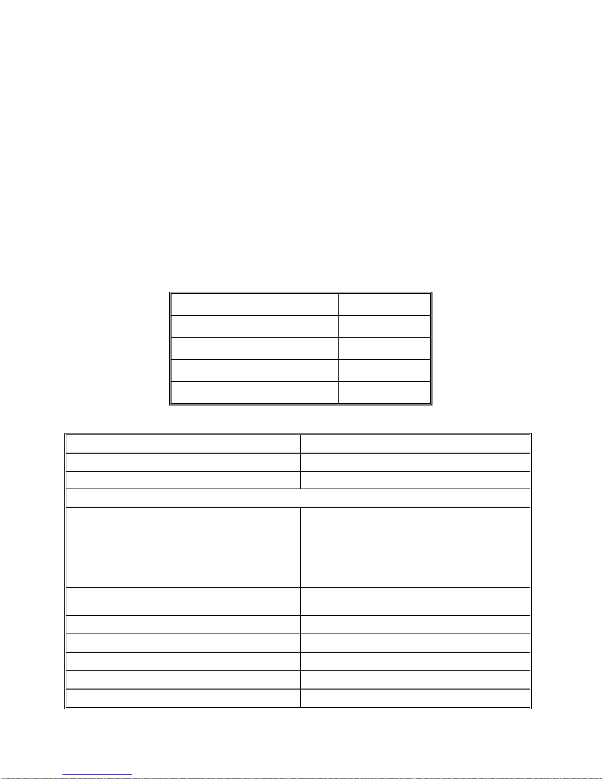
SUPPLIER FURNISHED COMPONENT MANUALS
COMPONENT MANUAL PART #
PT6A-60AG Maintenance Manual
Vol. I & II 3034342
Parts Manual 3034344
PT6A-65AG, PT6A-65AR,
PT6A-65B Maintenance Manual
Vol. I & II 3032843
Parts Manual 3032844
PT6A-45A, PT6A-45B,
PT6A-45R Maintenance Manual
Vol. I & II 3027042
Parts Manual 3027044
Propeller Owner’s Manual 139

THRUSH AIRCRAFT, INC – MODEL S2RHG-T65 TURBO THRUSH
AIRCRAFT MAINTENANCE MANUAL
1-4 Effective: 05/05/04
AIRCRAFT STRUCTURE
FUSELAGE
The fuselage is comprised of a welded tubular steel frame, fiberglass hopper, and
detachable skins. An overturn structure forms an integral part of the fuselage frame. The
frame structure, fittings, bushings, brackets, and so forth are fabricated from 4130
chrome-moly seamless steel tubing.
As a corrosion preventative, hot linseed oil is pumped throughout the entire welded
structure. On an average, 12 gallons are pumped into the frame and 11 to 11 ½ gallons
drain out, leaving a residual coating on all members. The exterior of the frame is
sandblasted, etched, and primed, which is followed by two coats of polyurethane paint
that is resistant to chemical reaction.
The fuselage is covered with heat treated Alclad panels attached with camloc fasteners.
Side skins can be removed using only a screwdriver, thus exposing the fuselage frame
for thorough cleaning and inspection. All skins are supported clear of the fuselage tubing
to prevent accumulation of corrosive chemicals. The seams and lap joints of the skin
panel support structure are sealed with a special compound to eliminate chemical action
between the mating surfaces. Each skin panel is etched, primed, and painted before
assembly to insure complete coverage. All bottom fuselage skins around the hopper
opening and aft to the tail post are made of stainless steel. The skin fasteners in the high
corrosion areas are also stainless steel. WING
The wing has a constant chord of 90 inches, and is all metal, full cantilever design. The
massive main spar is a tension field beam structure constructed from Alclad webs and
high strength heat-treated steel caps. All wing skins, ribs, and leading edges are
constructed from Alclad heat-treated material. The leading edge structure is made
especially strong to minimize denting and is riveted with universal rivets for strength. The
fuel tanks, which are located in the inboard section of the wing, are an integral part of the
structure. Close pitch riveting of the seams, substantial reinforcement, and flexible
sealants minimize chances of rupture in crash conditions. Drain holes are provided in
adjacent bays to prevent accumulation of fuel in the event of a leak. The ailerons and
flaps are all metal construction and are hinged on ball bearings. The flaps are electrically
operated by push rods and are completely sealed against chemical entry. Flap hinges
are stainless steel. EMPENNAGE
The horizontal stabilizer, elevator, rudder and vertical fin are an all-metal structure. All
skins, ribs and leading edges are constructed from alclad material. The movable surfaces
are hinged on sealed bearings that can be easily replaced. The rudder and the elevator
have aerodynamic balances that are protected by overhangs on the fixed surfaces.

THRUSH AIRCRAFT, INC – MODEL S2RHG-T65 TURBO THRUSH
AIRCRAFT MAINTENANCE MANUAL
Effective: 9/16/05 1-5
COCKPIT
There are two choices of the enclosed cockpit canopies for the Turbo Thrush (1) the
SINGLE cockpit canopy or (2) the DUAL cockpit canopy. The overturn structure of both
is exceptionally strong and welded to "hard points" in the fuselage frame. The forward
bracing supports the windshield support channels and is welded to a lateral tube that is
curved to provide more head clearance. The fiberglass canopy shell has extra thickness
on the top portion and is well attached to the extra large steel tube structure so that it will
serve as a skid in case of overturn. The large canopy doors permit easy entrance to one
or both cockpits. The doors should not be removed for flight, as the aircraft performance
will be lowered. The cockpit seat belts are anchored to the seat structure, and the
shoulder harnesses are secured to a steel channel at the bottom of the seat structure.
The seats adjust vertically. The rudder pedals adjust fore and aft. The windshield is a
three-piece construction. The center section is tempered safety plate glass for better
resistance to scratching and is enclosed in a stainless steel frame. The windshield side
panels are Plexiglas and are curved to provide streamlining.
AIRCRAFT SYSTEMS
HYDRAULIC SYSTEMS
The hydraulic system consists of two master brake cylinders with hydraulic lines
connecting the master cylinders to the wheel brake cylinders. Applying toe pressure on
the rudder pedals actuates the master cylinders, which are located just aft of the pilot’s
rudder pedals. A small reservoir is incorporated within each master cylinder to supply the
system with brake fluid. POWER PLANT & PROPELLER
The Turbo Thrush is powered by the PT6, a lightweight free turbine engine incorporating
a reverse flow combustion path, designed for aircraft propulsion use. It utilizes two
counter rotating turbine sections. One drives the compressor, and the other drives the
propeller through a reduction gearbox. The latter turbine is "free" or independent of the
compressor turbine. More recent and higher-powered models incorporate a two-stage
free turbine. The PT6 has been produced in several models and has been adapted to a
multitude of uses.
The propeller has five blades mounted on a hollow hub, in the front end of which is a
servo-piston that moves forward under servo-oil pressure or rearward under feather
return spring pressure, assisted by counterweights. There are five links from the servo-
piston, one going to each blade root. These links transmit forward motion of the servo-
piston to the blade roots and pivot the blades in the decrease pitch direction. When
servo-piston pressure is relieved, the servo-piston moves rearward under feather return
spring pressure and pivots the blades in the increase pitch direction. This action is
assisted by centrifugal force of the counterweight on each blade root.
FUEL SYSTEM
A 230-gallon fuel supply is available for the Turbo Thrush. In each wing, fuel is contained
inside integral wing tanks (wet wing fuel tanks) just outboard of the wing walks. The left
wing and right wing fuel tanks are interconnected through a 5 U.S. gallon header tank that
is located in the fuselage. The fuel supply lines, to the engine, are routed from the header
tank outlet finger screen through a fuel shutoff (on/off) valve to an electric driven fuel

THRUSH AIRCRAFT, INC – MODEL S2RHG-T65 TURBO THRUSH
AIRCRAFT MAINTENANCE MANUAL
1-6 Effective: 05/05/04
boost pump.
The electrically driven fuel boost pump serves two purposes, first as a backup system to
provide continuous fuel pressure to the engine high pressure fuel pump in case the
engine driven fuel boost pump fails and secondly to provide boosted fuel pressure to the
engine high pressure fuel pump during engine starting. The electric driven fuel boost
pump discharge is then routed through a 25-micron main fuel filter to an engine driven
fuel boost pump.
The aircraft’s fuel system is equipped with two fuel filters, a ¼ inch mesh finger strainer is
installed in the outlet fitting from the header tank and a 25-micron, airframe supplied, main
fuel filter located on the forward L/H side of the firewall. Fuel from the aircraft fuel system
enters the engines high pressure fuel pump which has two fuel filters of its own, an 74-
micron inlet filter and a 10-micron discharge filter (refer to the engine appropriate
maintenance manual for pertinent maintenance details for the engine supplied filters and
fuel system).
The fuel tank vent system is designed to keep the fuel spillage to a minimum. The fuel
tanks are vented through tubing connected at both the inboard and outboard ends of the
individual fuel tanks to the centrally located vent system in the fuselage. Ram air enters a
vent scoop, on the fuselage, under the left wing and pressurizes the vent system to
maintain positive pressure on the fuel tanks. The vent system is provided with two quick
drains, located on the fuselage under each wing, to drain any fuel that might happened to
have got in the tanks outboard vent lines.
At engine shutdown, fuel from the start control unit or the flow divider/dump valve, located
at the 6 o’clock position on the engine fuel nozzle manifold, is directed to a residue fuel
reservoir “EPA tank” mounted inboard on the L/H aft shin skin. This reservoir holds
approximately 3 engine shutdowns worth of fuel before the fuel will exit the reservoir vent
system. (NOTE: This reservoir should be emptied after each engine shutdown.) (NOTE:
It is common and normal after an engine compressor Water Wash or Performance
Recovery Wash to have water or soap appear in the reservoir’s drained waste fuel.)
The fuel quantity gauge is located on the lower left instrument panel. The fuel quantity
indicating system consists of two transmitters, one indicator gauge, and an L/H or R/H
tank fuel quantity selector switch. A transmitter installed in each wing tank transmits an
electrical signal to the single fuel quantity indicator. The instrument reads both the left
and right fuel tanks singularly as chosen by the electrical control switch, adjacent to the
fuel quantity indicator gauge on the instrument panel.
The two fuel tanks are serviced through filler ports located on the top of both wings. The
filler ports incorporate security chains to prevent the loss of the fuel caps. Service the
aircraft from refueling facilities that utilize proper ground handling equipment and filter
systems to remove impurities and water accumulation from the bulk fuel. If filtering
facilities are not available, filter the fuel through a quality high-grade chamois. Fuel tanks
should be serviced after the last flight of each day to reduce condensation and allow any
entrapped water accumulations to settle to the fuel system drains, to be removed, prior to
the next flight.
Prior to the first flight of the day the header tank and fuel filter should be drained to check
for the presence of water or sediment in the fuel system. If there is a possibility, at any
time, that any tank may contains water, the header tank and fuel filter should be drained
as necessary to ensure no water exists in the fuel system. For fuel system servicing

THRUSH AIRCRAFT, INC – MODEL S2RHG-T65 TURBO THRUSH
AIRCRAFT MAINTENANCE MANUAL
Effective: 9/16/05 1-7
information, refer to Section 2.
LANDING GEAR, WHEELS & BRAKES
The main landing gear is made using a formed chrome-moly spring steel unit. The left
main gear and the right main gear are symmetrical. The main wheels are 29 x 11. The
spring steel construction and design of the main gear allow for absorption of landing
weight and common stresses associated with such, thus eliminating the need for shock
struts. The brake system has individual toe brakes and individual park brakes. The use of
a special N-513 compound cup in each master cylinder permits the use of MIL-H-5606, a
heavy-duty aviation hydraulic fluid. The brakes are dual caliper disc types. The tail gear
is a spring steel type and uses a 6.00 x 6 tailwheel.
FLIGHT CONTROLS
The flight controls are of conventional design employing extensive use of ball bearings for
low friction and smoothness of operation. The aileron and elevator controls are push rod
systems and the rudder control is through cables. The elevator trim control is actuated by
a lever that moves the tab to the desired position through push rods. The wing flaps are
operated electrically and controlled by a switch located on the left side of the cockpit. The
rudder controls are interconnected by springs to the aileron system so that a wing may be
lifted with the rudder alone. INSTRUMENTS
The standard instruments are located on three separate panels: An upper panel, a left
panel, and a right panel. The left panel contains a clock, oil temperature, hour meter, fuel
pressure, oil pressure, air filter Delta “P”, and fuel quantity gauges. The right panel
contains a voltmeter, ammeter, and circuit breakers. The upper panel contains all engine-
warning lights, torque pressure, ITT indicator, Gas Generator percent RPM, Propeller
RPM and standard flight instrument package.
ELECTRICAL SYSTEM
The standard 24 volts and 105 amp electrical system consists of the starting system, the
navigation lights, the wiper/washer system, and the strobe lights. The landing lights, the
working lights, and the air conditioner system are optional. The landing and working
lights may be installed in the field, since the wiring for them is included in the standard
wire bundle. The electrical system obtains power from two 24-volt batteries and one
starter/generator. An external power receptacle is standard equipment and may be used
for connecting a 24-volt ground power unit to the aircraft for engine starting or
maintenance. The ground start system utilizes the master relay so that starting is
accomplished by engaging the starter switch.
AIRCRAFT WEIGHT & BALANCE
Refer to S2RHG-T65 Flight Manual for aircraft weight and balance information.
THRUSH AIRCRAFT, INC – MODEL S2RHG-T65 TURBO THRUSH
AIRCRAFT MAINTENANCE MANUAL
1-8 Effective: 05/05/04
Figure 1-1: Aircraft 3-view
THRUSH AIRCRAFT, INC – MODEL S2RHG-T65 TURBO THRUSH
AIRCRAFT MAINTENANCE MANUAL
Effective: 05/05/04 1-9
Figure 1-2: Aircraft Stations

THRUSH AIRCRAFT, INC – MODEL S2RHG-T65 TURBO THRUSH
AIRCRAFT MAINTENANCE MANUAL
Effective: 09/16/05 2-1
SECTION 2
SERVICING & INSPECTION
TABLE OF CONTENTS
SERVICING & INSPECTION..........................................................................................3
GROUND HANDLING ....................................................................................................3
TOWING....................................................................................................................3
TAXIING ....................................................................................................................3
PARKING...................................................................................................................3
MOORING.................................................................................................................3
JACKING...................................................................................................................4
LEVELING .................................................................................................................4
COLD WEATHER OPERATION.....................................................................................4
COLD WEATHER MAINTENANCE HINTS ...............................................................4
GROUND EMERGENCY PROCEDURES...................................................................... 5
ENGINE FIRES..........................................................................................................5
ELECTRICAL FIRES.................................................................................................5
GROUND OPERATION OF ENGINE ............................................................................. 6
BEFORE STARTING ENGINE ..................................................................................6
STARTING ENGINE..................................................................................................6
ENGINE OPERATIONAL CHECK.............................................................................7
SYSTEM AND COMPONENT SERVICING.................................................................... 8
HYDRAULIC SYSTEM ..............................................................................................8
ENGINE OIL SYSTEM...............................................................................................8
FUEL SYSTEM........................................................................................................11
DEFUELING ............................................................................................................13
INDUCTION SYSTEM.............................................................................................14
LANDING GEAR, WHEELS & BRAKES...................................................................... 14
TIRES......................................................................................................................14
BRAKE BLEEDING..................................................................................................14
INSPECTION ................................................................................................................ 14
INSPECTION CHECK LIST..................................................................................... 15
INSPECTION CHART...................................................................................................16
PROPELLER ...........................................................................................................16
ENGINE EXTERNALS.............................................................................................17
ENGINE OIL SYSTEM.............................................................................................18
OIL COOLER AUGMENTATION (GROUND).......................................................... 19
ENGINE FUEL SYSTEM.........................................................................................19
IGNITION SYSTEM.................................................................................................20
PNEUMATIC SYSTEM............................................................................................21
AIRFRAME FUEL SYSTEM ....................................................................................21
MAIN LANDING GEAR............................................................................................21
TAIL GEAR..............................................................................................................22

THRUSH AIRCRAFT, INC – MODEL S2RHG-T65 TURBO THRUSH
AIRCRAFT MAINTENANCE MANUAL
2-2 Effective 9/16/05
FUSELAGE SKINS.................................................................................................. 24
HOPPER..................................................................................................................24
WINGS.....................................................................................................................24
FUSELAGE FRAME................................................................................................25
CONTROL SYSTEMS.............................................................................................26
METAL EMPENNAGE.............................................................................................27
AILERONS AND FLAPS..........................................................................................27
COCKPIT.................................................................................................................28
ELECTRICAL SYSTEM...........................................................................................29
CORROSION CONTROL .............................................................................................29
WINDSHIELD ..........................................................................................................30
HOPPER REPAIR ...................................................................................................30
FUEL TANK REPAIR...............................................................................................30
BATTERY MAINTENANCE.....................................................................................30
Figure 2-1: Tie Down and Jack Points...............................................................32
Figure 2-2: Wing Fuel Fillers and Drains ........................................................... 33
Figure 2-3: Fuselage Fuel Drains......................................................................34
Figure 2-4: Fuel Filter Location..........................................................................35
Figure 2-6: Lubrication Chart..............................................................................36
Figure 2-7: Torque Chart....................................................................................44
Figure 2-8: Engine Oil Servicing.........................................................................45

THRUSH AIRCRAFT, INC – MODEL S2RHG-T65 TURBO THRUSH
AIRCRAFT MAINTENANCE MANUAL
Effective: 05/05/04 2-3
SERVICING & INSPECTION
Standard procedure for ground handling, servicing, inspection, airframe maintenance,
lubrication, and storage are included in this Section. Adherence to these procedures on a
scheduled basis can save many hours of maintenance and aircraft down time. When a
system component requires service or maintenance other than that outlined in this
Section, refer to the applicable Section of this manual for complete information.
GROUND HANDLING
TOWING
Movement of the aircraft on the ground may be accomplished as follows:
A. Pull and guide the aircraft by means of a tow bar with the tail wheel unlocked.
B. Attach a rope harness to the main gear when there is a need to tow the aircraft
forward through snow or over soft and/or muddy ground.
TAXIING
Before attempting to taxi the aircraft, maintenance personnel should be checked out by
qualified personnel. When it is determined that the propeller area is clear, apply the
power to start the taxi roll and perform the following:
A. Push the stick full forward to unlock the tail wheel.
B. Taxi a few feet and check the brake operation.
C. While taxiing, make slight turns to determine that the tail wheel steering is
operative.
D. Avoid taxiing over ground of loose stones, gravel, or other loose material that
may cause foreign object damage to the propeller or to other aircraft in the area.
E. You may taxi with the power lever in the Beta region to govern ground speed.
Observe all engine operating limits.
PARKING
Head the aircraft into the wind and set the parking brake. Do not set the parking brake
during cold wet weather because the accumulated moisture may freeze in the brakes. Do
not set the parking brake if the brakes are overheated. Install the internal control lock.
Place the chocks under each main wheel.
MOORING
Park aircraft as previously outlined. In winds up to 20 knots, secure the aircraft at the
wing tie down rings. For winds above 20 knots, tie the tail and main gear as well as the
wings. Install external control surface locks. Be sure to tie the propeller down to prevent
it from wind milling with zero oil pressure. The aircraft should be placed in a hangar when
wind velocity is predicted to exceed 50 knots. When mooring aircraft, use 3/4-inch manila
or nylon rope. A clove hitch or other anti-slip knot should be employed. If a manila rope
is used for tie down, allow enough slack to compensate for contraction of the rope fiber
without damaging the aircraft.
Table of contents
Other Thrush Aircraft Aircraft manuals


Popular Aircraft manuals by other brands


Aeros
Aeros PROFI TL Owner's service manual

Reely
Reely Phoenix XS 2.0 operating instructions

MAULE
MAULE M-7-260C Airplane Flight Manual

Dudek
Dudek Nucleon WRC user manual

Piper Aircraft Corporation
Piper Aircraft Corporation PA-28-181 Airplane Maintenance Manual

Van's Aircraft
Van's Aircraft RV-7 Flight manual


