TIELBURGER tk 520 User manual

This document is a publication by Julius Tielbürger GmbH & Co. KG, Postdamm 12, D-32351 Stemwede-Oppenwehe, Germa-
ny (www.tielbuerger.de).
The document is up to date with the latest technology at the time of printing. Subject to technical and equipment changes. The
drawings and illustrations shown may differ from the original.
$OOULJKWVUHVHUYHGLQFOXGLQJWKRVHRIWUDQVODWLRQ$Q\W\SHRIUHSURGXFWLRQVXFKDVSKRWRFRS\PLFUR¿OPRUVWRULQJLQHOHF-
tronic data processing systems, requires written authorisation from the publisher. Any reproduction, whether in whole or in
part, is prohibited.
All trademarks, registered trademarks, trade names and brand names are the property of their rightful owners and are acknowl-
edged by us.
© Copyright 2017 by Julius Tielbürger GmbH & Co. KG

3
3
Content
1 Operating and installation instructions ....................................................................................................................... 4
1.1 General ..................................................................................................................................................................... 4
1.2 Warnings and symbols.............................................................................................................................................. 5
2 Basic safety instructions ................................................................................................................................................ 6
2.1 Intended use.............................................................................................................................................................. 6
2.2 Organisational measures........................................................................................................................................... 6
3HUVRQQHOVHOHFWLRQDQGTXDOL¿FDWLRQVEDVLFREOLJDWLRQV......................................................................................... 7
2.4 Position of safety stickers and labels........................................................................................................................ 7
3 Scope and condition of delivery.................................................................................................................................... 8
4 Illustration of the machine and danger zone, component description, position of safety stickers and labels....... 9
4.1 Components of the Tielbürger quick-change system ............................................................................................. 10
4.2 Accessories ............................................................................................................................................................. 10
5 Installation.....................................................................................................................................................................11
5.1 Preparatory measures prior to installation.............................................................................................................. 11
5.2 Installation .............................................................................................................................................................. 12
5.3 Drive set installation............................................................................................................................................... 13
5.4 Sweeper attachment installation............................................................................................................................. 25
6 Start-up ......................................................................................................................................................................... 31
6.1 Basic safety instructions for normal operation....................................................................................................... 31
6.2 Coupling and uncoupling the sweeper ................................................................................................................... 32
6.3 Brush pressure ........................................................................................................................................................ 34
6.4 Setting the ejection direction.................................................................................................................................. 35
6.5 Debris container .................................................................................................................................................... 36
6.6 Emptying the debris container ............................................................................................................................... 37
6.7 Removing the debris container............................................................................................................................... 38
6.8 Switching the brush on and off............................................................................................................................... 39
7 Maintenance and care.................................................................................................................................................. 40
7.1 Basic safety instructions......................................................................................................................................... 40
7.2 Replacing the sweeper brushes............................................................................................................................... 41
7.3 Cleaning the implement.......................................................................................................................................... 42
7.4 Additional cleaning instructions............................................................................................................................. 43
7.5 Checking and correcting the tyre pressure ............................................................................................................. 44
7.6 Storage.................................................................................................................................................................... 45
7.7 Maintenance plan ................................................................................................................................................... 45
8 Transport ...................................................................................................................................................................... 46
9 Potential faults and how to rectify them .................................................................................................................... 46
10 Terms of the guarantee ............................................................................................................................................. 47
11 Exploded drawings .................................................................................................................................................... 47
12 Drive set – exploded drawing.................................................................................................................................... 48
13 Sweeper attachment – exploded drawing ................................................................................................................ 49
14 EC Declaration of Conformity.................................................................................................................................. 54

1.1 General
Operating and installation instructions
1 Operating and installation instructions
4
e operating and installation instructions are intended
to help users familiarise themselves with the machine
and use it in line with its intended applications.
e operating and installation instructions contain
important information on how to operate the machine
safely, properly and economically. Observing these op-
eratingandinstallationinstructionshelpstoavertrisks,
to reduce repair costs and downtime and to increase
the reliability and service life of the machine.
e operating and installation instructions must always
be available at the location where the machine is used.
eoperatingandinstallationinstructionsmustbe
read and applied by any person in charge of carrying
out work with or on the machine, for example:
-Operation, including setting up, fault rectication
in the course of work, removal of production waste,
maintenance and disposal of operating and auxiliary
materials
-Maintenance (servicing, inspection, repair) and/or
-Transport.
e generally recognised rules of technology for safe
andproperworkingmustbeobservedinadditiontothe
operating and installation instructions and mandatory
regulations for accident prevention which apply to the
country and place of use.
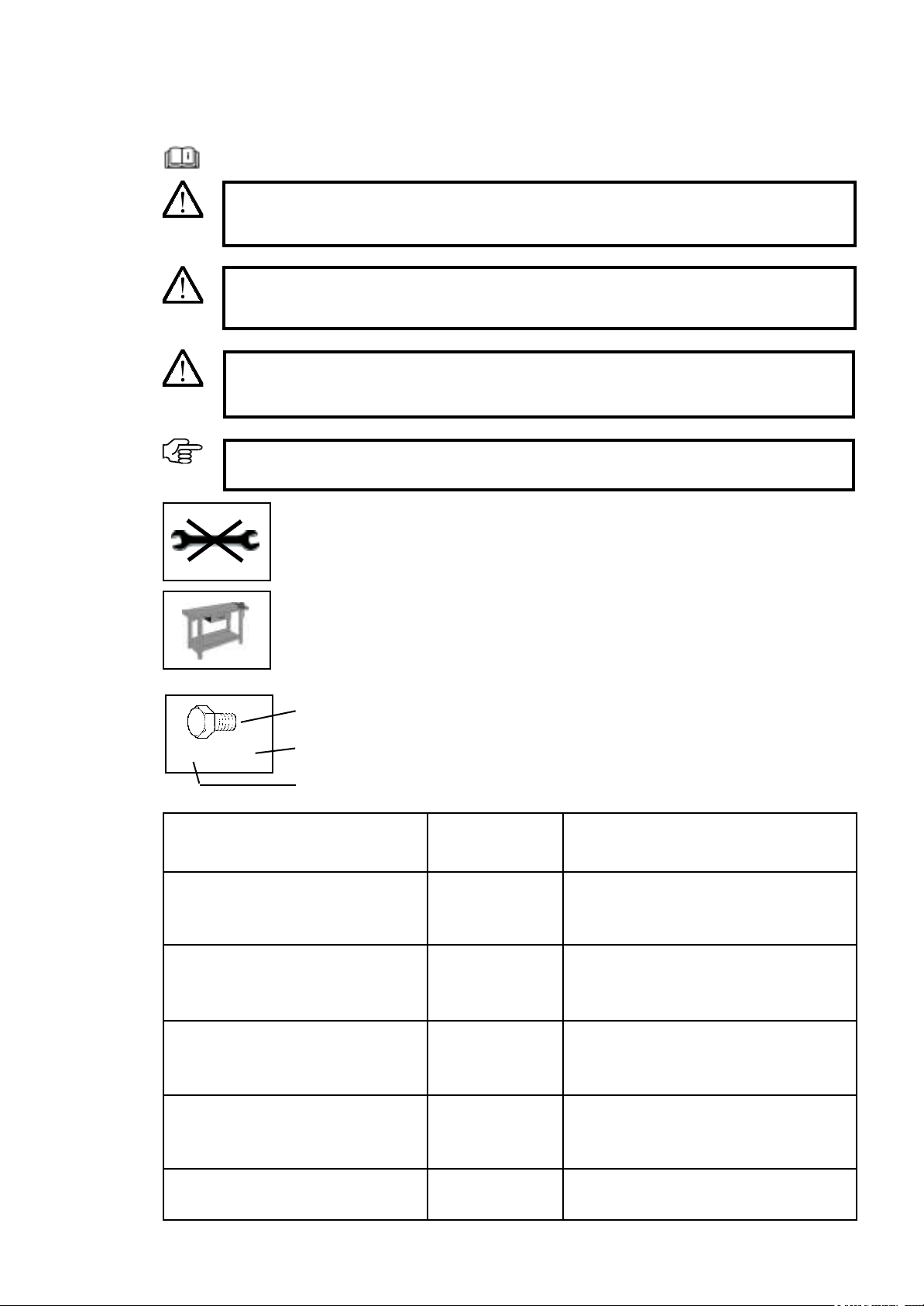
Read the operating instructions
1.2 Warnings and symbols
WARNING:
Indicates a potentially hazardous situation. If this instruction is ignored, there may be a
risk of death or extremely serious injury.
CAUTION:
Indicates a potentially hazardous situation. If this instruction is ignored, there may be a
risk of minor injury.
IMPORTANT:
Indicates operating tips and other useful information.
5
Operating and installation instructions
Work on a workbench
Do not use a tool
DANGER!
Indicates an immediate threat of danger. If this instruction is ignored, there is a risk of
death or extremely serious injury.
Symbol
Type
Quantity
2x M8 x 20
Symbol
Bolt
Washer
Nut
Combination spanner
Hexagon head screwdriver
Screwdriver
Crosshead screwdriver
Type
Examples:
M8 x 16
8,1 - 58 - 5
M8 (L)
8
PZ 2
PH 2
Explanation
M=Metric
S=Diameter in mm
16 =Length in mm
8.1 =Inner diameter
58 =Outer diameter
5=Material thickness in mm
M=Metric
8 =Inner diameter in mm
(L) =Lock nut
8=Size in mm
PZ 2 = Pozidriv size 2
PH 2 = Phillips size 2

Basic safety instructions
6
2.2 Organisational measures
e operating and installation instructions must always
be kept ready at thelocation where the machine isused.
In addition to the operating and installation instruc-
tions, observe and follow the generally valid legal reg-
ulations and any other binding regulations for accident
prevention and environmental protection.
Suchobligationsmay alsoincludehandlinghazard-
ous substances or making available/wearing personal
protective equipment and complying with road trac
regulations, for example.
Supplement the operating and installation instruc-
tions by instructions as well as site management and
reporting obligations concerning special operational
requirements, for example with regard to work organ-
isation, workows, personnel used, etc.
Any personnel instructed to perform work on the
machine must have read the operating instructions
before starting work, specically the section entitled
"Safety instructions". Reading the instructions aer
work has begun is too late. is applies in particular to
personnel who only work on the machine occasionally,
for example for set-up and maintenance.
At least occasionally, check that the personnel are work-
ing with safety and hazards in mind and are following
the operating instructions.
Personnel must not have long hair which is not tied
back or wear loose clothing or jewellery including rings.
ere is a risk of injury from being caught or drawn
into the machine, for example.
Wear personal protective equipment if necessary or
required by regulations.
Observe all safety and hazard notices on the machine.
Ensure that all safety and hazard notices at/on the
machine can be read in full at all times.
In the event of any modication to the machine or any
change in the machine's performance that may aect
safety, shut down the machine immediately and report
the fault to the responsible specialist dealer.
Do not modify, convert or attach equipment to the
machine without approval from the manufacturer if
this could impair safety. is also applies to tting and
adjusting safety equipment and valves, as well as for
welding on supporting parts.
Use only genuine spare parts from the manufacturer.
ese comply with the technical requirements and
safeguard your warranty and guarantee rights. Adhere
to the prescribed time periods or those indicated in the
operating and installation instructions for recurring
tests/inspections.
Workshop equipment which is appropriate for the work
is mandatory for carrying out maintenance measures.
Make personnel aware of the location of re extinguish-
ers and how to use them.
Comply with the re alarm and reghting procedures.
2.1 Intended use
e product has been constructed using state-of-the-art
technology and in line with the recognised technical
safety regulations. However, use of this product may
still result in the risk of injury or death to the user or
third parties, or of damage to the product and other
material assets.
Only use the product in technically perfect working
order, for its intended use and with safety and hazards
in mind, in compliance with the operating and instal-
lationinstructions. Inparticular, youmustimmediately
rectify faults that could impair safety or have such faults
rectied immediately by a third party.
e product is exclusively intended to be installed on
the machines approved by the manufacturer and is
intended for the accessories approved by the manufac-
turer. Any other or additional form of use, for example
use in conjunction with self-constructed accessories,
shall be regarded as non-compliant with the intended
use. is product is solely intended for sweeping ap-
plications as part of grounds maintenance and winter
road maintenance. Any other or additional form of use
is considered non-compliant with the intended use.
For example, the product must not be used to sweep
animal feed. Bristles can come loose and be consumed
by animals, harming the animal. e manufacturer/
supplier shall not be held liable for any damage or loss
suered as a result. e risk is borne solely by the user.
Intended use also includes complying with the oper-
ating and installation instructions and adhering to the
inspection and maintenance conditions.
is sweeper may only be operated with brushes that
have been approved by the manufacturer.
e implement is solely intended for clearing dirt on
roads, foliage and snow. Any other applications are
not permitted.
Unauthorised operators:
Persons who are not familiar with the operating in-
structions, minors and persons under the inuence
of alcohol, drugs or medication must not operate the
implement.
2 Basic safety instructions

7
2.3 Personnel selection and qualications; basic obligations
Work on/with the product may only be carried out by
reliable personnel. Observe the legal minimum age.
Only use trained or instructed personnel and clearly
dene the responsibilities of the personnel for opera-
tion, set-up, maintenance and repair.
Ensure that only authorised personnel work on the
product.
Only allow personnel who are yet to complete training,
instruction and induction or who are still completing a
general apprenticeship to carry out work on the prod-
uct under the constant supervision of an experienced
person.
Work on the product's electrical equipment may only
be carried out by a qualied electrician or by trained
personnel under the guidance and supervision of a
qualied electrician in accordance with electrical en-
gineering regulations.
Work on chassis, braking and steering systems must
only be carried out by qualied personnel trained for
such work.
Only personnel who possess specic knowledge of and
experience in hydraulics are allowed to carry out work
on hydraulic equipment.
Clean the implement regularly, particularly in the ex-
haust and engine area. Otherwise, there is an increased
risk of re.
Basic safety instructions
2.4 Position of safety stickers and labels
Caution:
Hot surface
Do not open the pro-
tective equipment,
risk of crushing


1
9
Illustration of the machine and danger zone
4 Illustration of the machine and danger zone, component description, position of safety stickers and labels
1. Danger zone
2. Lever for raising and lowering the sweeper
3. Swivelling lever for laterally adjusting the sweeper brushes
4. Ball handle for adjusting the height of the brushes
5. Mount for the debris container
6. Support wheel
7. Sweeper brush
8. Serial number
9. Machine designation
10. Manufacturer name
11. Weight
12. Year of construction
13. CE marking
14. Engine power
15. Engine manufacturer
16. Manufacturer address
17. Part number
A hazard is posed by ejected particles
while the engine is running – keep a
safe distance.
Max. speed 5 km/h
Before putting the machine
into operation, read and
take note of the operating
and safety instructions.
10
9
15
14
11
12
13
16
17
8
234
5
76
Ø = 15 m

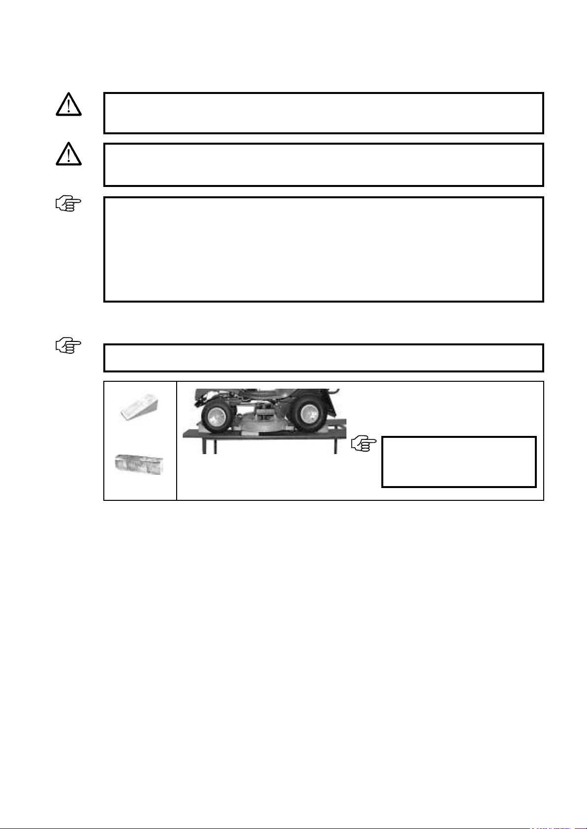
Installation
Installation should be performed on a height-adjustable work platform in accordance with the following instruc-
tions.
Lower the mower on to timber.
Secure the lawn tractor against rolling away by
using wheel chocks.
11
2x
5.1 Preparatory measures prior to installation
5 Installation
1x
IMPORTANT:
Follow the operating instructions
provided by the manufacturer for
this.
IMPORTANT:
Comply with the safety regulations for the work platform.
DANGER!
There is an increased risk of injury near running drives. Follow the safety instructions.
IMPORTANT:
The construction sets supplied must be checked to ensure that they are complete using the spare
parts list in these instructions.
The quick-change system should only be installed by a specialist dealer of engine units.
Before you begin, acquire an overview of the installation sequence and the required parts and tools.
The machine must be clean and in technically correct working order.
Follow the lawn tractor manufacturer's safety instructions and operating instructions.
WARNING:
Switch off the engine and allow it to cool down. The machine must be secured to prevent it from being
started inadvertently. Remove the ignition key and activate the parking brake.

12
Dear valued customer,
Models are continuously being updated by the lawn tractor and implement manufacturers in line with technolog-
ical progress. As a result, descriptions or illustrations in these instructions may differ from the actual conditions
on the lawn tractor.
Select one of the columns below on the basis of your mounting frame.
Column A=Attachment parts without quick-change mechanism,
for securely attached accessories
Column B=Attachment parts with quick-change mechanism,
for non-driven implements (e.g. clearing blade)
Column C=Attachment parts with quick-change mechanism with drive,
for driven implements (e.g. sweepers) and
for non-driven implements
1)During installation, only those steps which are marked with a point •
in the selected columns have to be carried out. Highlight the column that applies using a highlighter.
2) The sequence given in the installation instructions must be complied with.
Installation
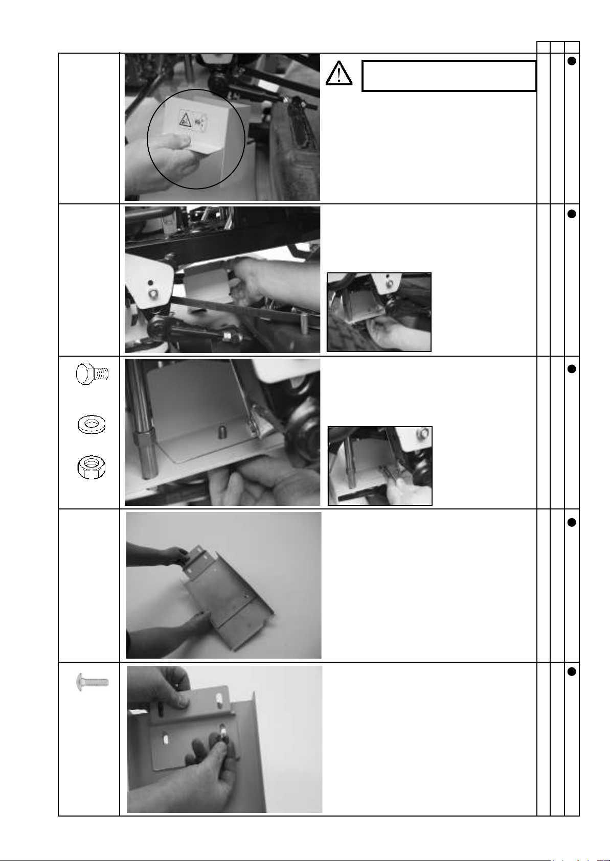
5.2 Installation
DANGER!
It is necessary to remove protective equipment in order to install attachment parts. You must there-
fore ensure that this equipment is reattached after installation is complete. This is why none of the
following work steps can be ignored.
DANGER!
The installation procedure described below must only be performed by the specialist dealer.

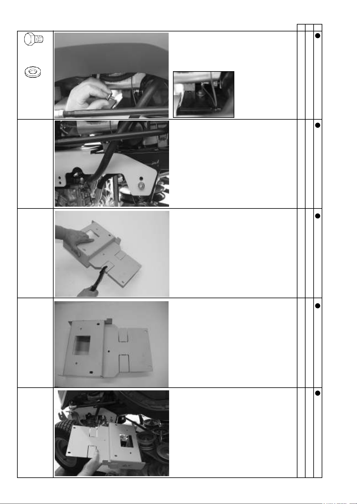
Push the bolt with washer through the hole.
On a (2wd) rear-wheel drive tractor:
Remove parts.
Position the bracket.
Installation
14
AB C
2x M8 x 16
2 x 8.4-25-2
On a (4wd) all-wheel drive tractor:
Do not remove parts.
Loosely pre-assemble the spacer.

Tighten all bolts.
Turn the nut with washer on the bolt.
Push the bolt with washer through the hole.
Remove the castors.
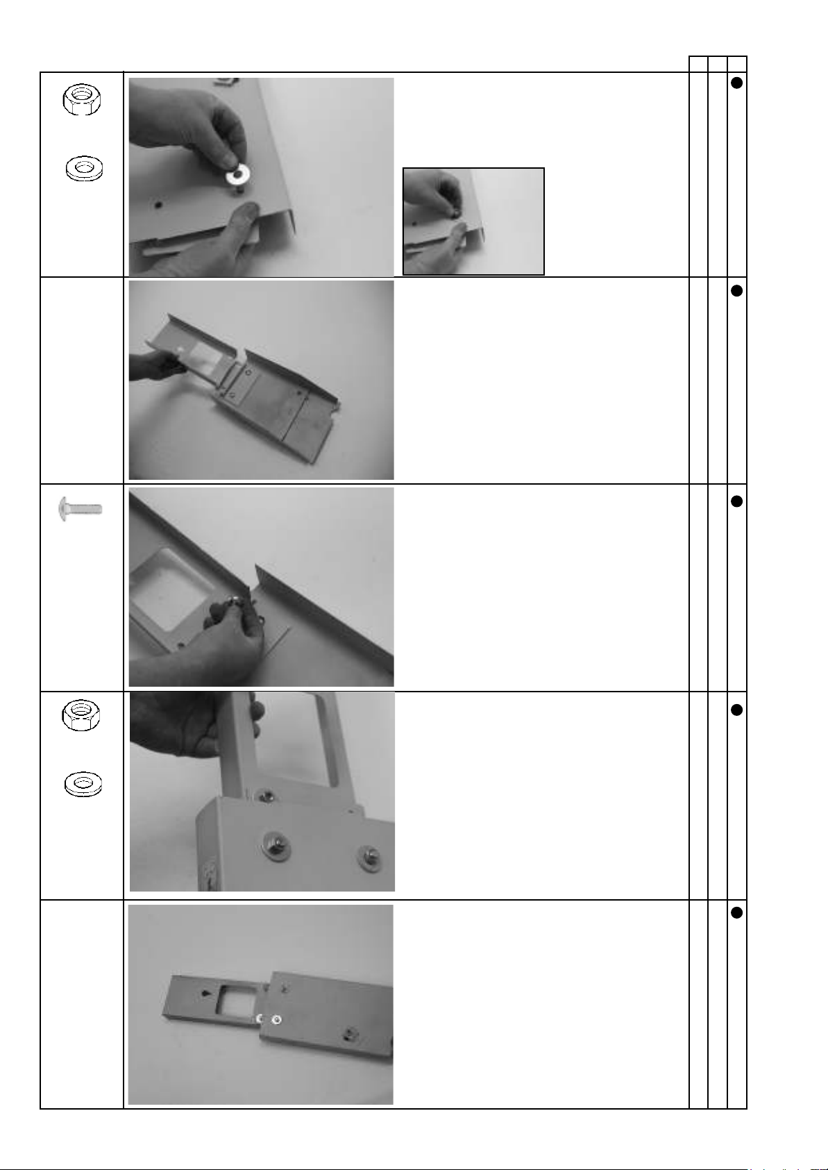
Installation
15
AB C
Push the bolt with washer through the drilled
hole and screw it into the spacer.
2x M8 x 16
2 x 8.4-25-2
2x M8 x 20
2x
2 x 8.4-25-2
2 x 8.4-25-2
2x M8

Installation
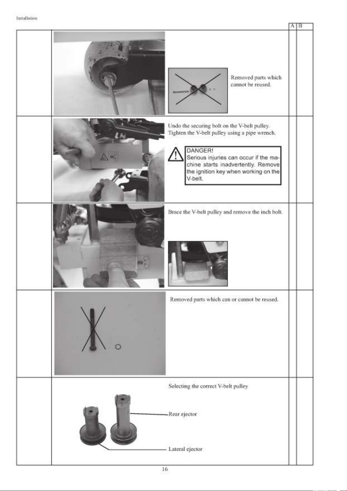
17
AB C
1x 7/16" x
20 UNF x
3 1/2“
Push the washer onto the bolt.
Lateral ejector
Rear ejector
Push the bolt with washer through the hole.
Install theV-belt pulley using theinch bolt and
tighten it.
Move the V-belt tensioner against the force of the
spring and place the V-belt on the quick-release
coupling's V-belt pulley.
IMPORTANT:
Tightening torque: 55-60 Nm. Tighten
the V-belt pulley using a hook wrench
to prevent it from turning.
DANGER!
Only rotate the V-belt pulley if the ig-
nition key has been removed.
CAUTION!
Take care to mount the V-beltpulley
correctly.

Installation
18
AB C
The V-belt is then placed on the V-belt pulley below
the engine.
Start the engine.
WARNING:
Risk of injury! Do not reach into the
V-belt while it is in operation.
Read the operating instructions
provided by the lawn tractor manu-
facturer.
Check that the V-belt drive is running correctly
(V-belt pulley running true) – see the information
on installing the V-belt pulley. Check that the V-belt
is running freely and whether the edges of the
V-belt are in contact with the V-belt idler pulley,
optimising the alignment if necessary.
DANGER!
Switch the engine off again.
Keep a safe distance from hot sur-
faces.
Release the tension spring so that the V-belt tensioner
comes into operation.
CAUTION:
The spring is tensioned.
Risk of crushing.
CAUTION!
6XI¿FLHQW FOHDUDQFH PXVW EH PDLQ-
tained between the mower and V-belt
pulley.
Installation
19
AB C
CAUTION!
Only use on rear ejectors.
Push the bolt through the drilled hole in the
¿QJHUJXDUG
2x M8 x 16
On rear ejectors only
Position the guard.
3RVLWLRQWKH¿QJHUJXDUG
On rear ejectors only
Push the bolt with washer through the drilled hole
in the bracket.
2x M8x16x20
2x 8.4-16-1.6 Turn the nut with
washer on the bolt.
Tighten the bolts.
2x M8
Installation
20
AB C
Push the nut with washer onto the bolt.
2x 9-28-3
2x M8
Position the guard.
Push the bolt through the drilled hole in the
guard.
Turn the nut with washer on the bolt.
2x M8 x 16
2x 9-28-3
2x M8
This manual suits for next models
1
Table of contents


