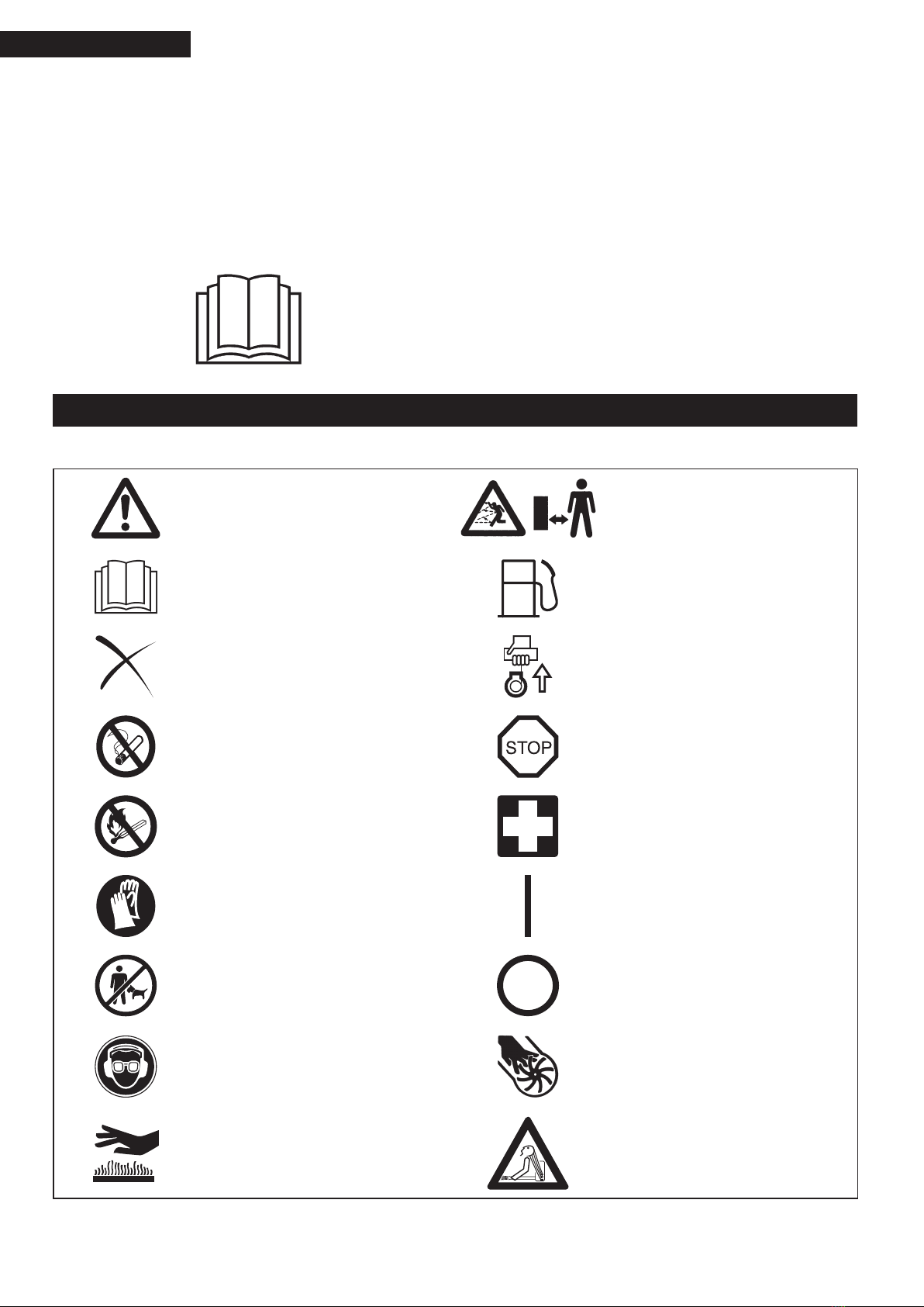
Makita EB7650TH User guide

Original Instruction Manual
Інструкція з експлуатації
Oryginalna instrukcja obsługi
Manual de utilizare original
Original-bedienungsanleitung
Eredeti kezelési kézikönyv
Pôvodný návod na obsluhu
Originální návod k použití
Important:
Read this instruction manual carefully before putting the Blower into operation and strictly observe the safety regulations! Preserve
instruction manual carefully!
Важливо:
Уважно прочитайте цю інструкцію перед використанням пристрою та чітко дотримуйтеся вимог безпеки! Дбайливо зберігайте цю
інструкцію!
Ważne:
Należy uważnie przeczytać instrukcję obsługi przed rozpoczęciem eksploatacji dmuchawy oraz przestrzegać przepisów dotyczących
bezpieczeństwa! Instrukcję obsługi należy przechowywać w bezpiecznym miejscu!
Important:
Citiţi cu atenţie acest manual înainte de a pune suanta în funcţiune şi respectaţi cu stricteţe reglementările de siguranţă! Păstraţi cu grijă
manualul de utilizare!
Wichtig:
Lesen Sie diese Bedienungsanleitung sorgfältig durch, bevor Sie das Blasgerät in Betrieb nehmen, und halten Sie sich strikt an die
Sicherheitsvorschriften! Bewahren Sie die Bedienungsanleitung sorgfältig auf!
Fontos:
Mielőtt a fúvót használni kezdené, olvassa el gyelmesen a kezelési kézikönyvet, és szigorúan tartsa be a biztonsági szabályokat! Őrizze
meg a kezelési kézikönyvet későbbi használatra!
Dôležité upozornenie:
Pred uvedením dúchadla do činnosti si pozorne prečítajte tento návod a prísne dodržiavajte bezpečnostné predpisy! Návod uchovajte na
bezpečnosm mieste!
Důležité:
Předtím než foukač budete používat, přečtěte si pečlivě tento návod a důsledně se řiďte bezpečnostními předpisy! Návod k použití si
pečlivě uschovejte!
EB7650TH EB7650WH

2
3
Thank you very much for selecting the Makita blower. We are pleased
to be able to offer you the Makita blower, which is the result of a long
development program and many years of knowledge and experience.
Those blower models combine the advantages of state-of-the-art
technology with ergonomic design. They are of lightweight, handy,
compact and represent professional equipment for a great variety of
applications.
Please read, understand and follow this booklet, which refers in detail
to the various points that will demonstrate its outstanding performance.
This will assist you to safety obtain the best possible results from your
Makita Blower.
English
SYMBOLS
It is very important to understand the following symbols when reading this instructions manual.
WARNING/DANGER Keep bystanders away
Read, Understand and Follow Instruction
Manual Fuel (Gasoline)
Forbidden Engine-manual Start
No Smoking Emergency Stop
No Open Flame First Aid
Protective Gloves must be Worn ON/START
Keep the Area of Operation
Clear of All Persons and Pets OFF/STOP
Wear Eye and Ear Protection Severing of ngers or hand, impeller blade
Hot surfaces – Burns to ngers or hands Long hair may cause entanglement
accident.
Table of Contents
Page
Symbols ................................................................................................ 2
Safety instructions ................................................................................ 3
EC declaration of conformity ................................................................ 6
Technical data....................................................................................... 7
Designation of parts.............................................................................. 8
Assembly instructions ........................................................................... 9
Before starting the engine .................................................................. 10
Operation ............................................................................................ 12
Adjustment of idling ............................................................................ 14
Prevention from carburetor icing ........................................................ 14
Operation method ............................................................................... 15
Inspection and maintenance............................................................... 17
Storage ............................................................................................... 19
Troubleshooting .................................................................................. 21

2
3
SAFETY INSTRUCTIONS
General Instructions
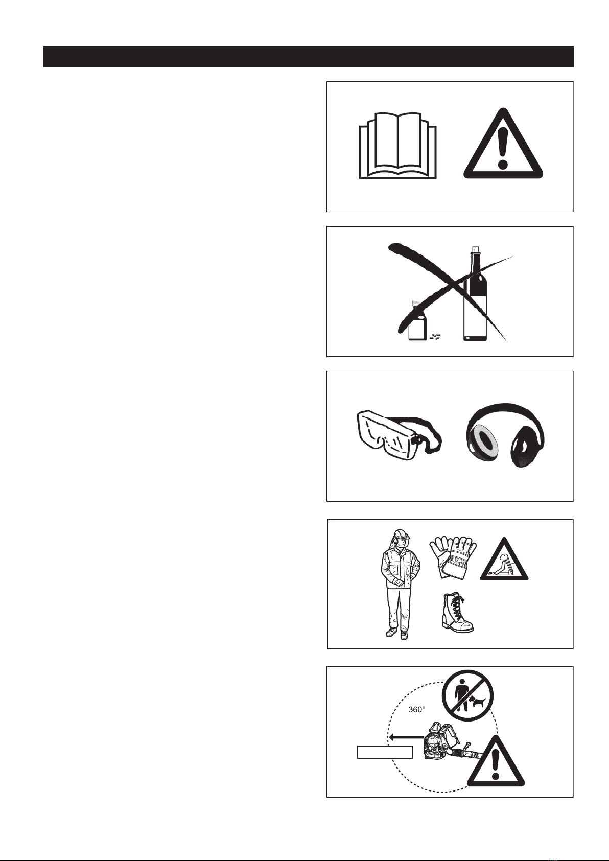
To ensure correct and safe operation, the user must read, understand and
follow this instruction manual to assure familiarity with the handling of the
blower (1). Users insufciently informed will risk danger to themselves as
well as others due to improper handling.
It is recommended only to loan the blower to people who have proven to
be experienced with blowers.
Always hand over the instruction manual.
First-time users should ask the dealer for basic instructions to familiarize
oneself with the handling of a blower.
Children and young persons aged under 18 years must not be allowed
to operate the blower. Persons over the age of 16 years may however
use the tool for the purpose of being trained only while under the direct
supervision of a qualied trainer.
Use blowers with the utmost care and attention.
Operate the blower only if you are in good physical condition.
Perform all work conscientiously and carefully. The user has to accept
responsibility for others.
Never use the blower while under the inuence of alcohol or drugs (2).
Do not use the unit when you are tired.
Save these instructions for future referral.
Personal Protective Equipment
The clothing worn should be functional and appropriate, i. e., it should
be tight tting but not cause a hindrance. Do not wear jewelry, clothing or
long hair which could be drawn into the air intake.
In order to avoid head-, eye-, hand- or foot injuries as well as to protect
your hearing the following protective equipment and protective clothing
must be used during operation of the blower.
Pay particular attention to the following regulations
Clothing must be sturdy and snug-tting, but allow complete freedom of
movement. Avoid loose-tting jackets, ared or cuffed pants, scarves,
unconned long hair or anything that could be drawn into the air intake. (4)
Wear overalls or long pants to protect your legs.
Do not wear shorts. (4)
Generally, engine products are noisy and their noise may damage your
hearing. Wear sound barriers (ear plugs or ear mufers) to protect your
hearing. Continual and regular users should have their hearing checked
regularly. (3)
Use of gloves when working with the blower is recommended.
Wear sturdy shoes with non-slip soles. (4)
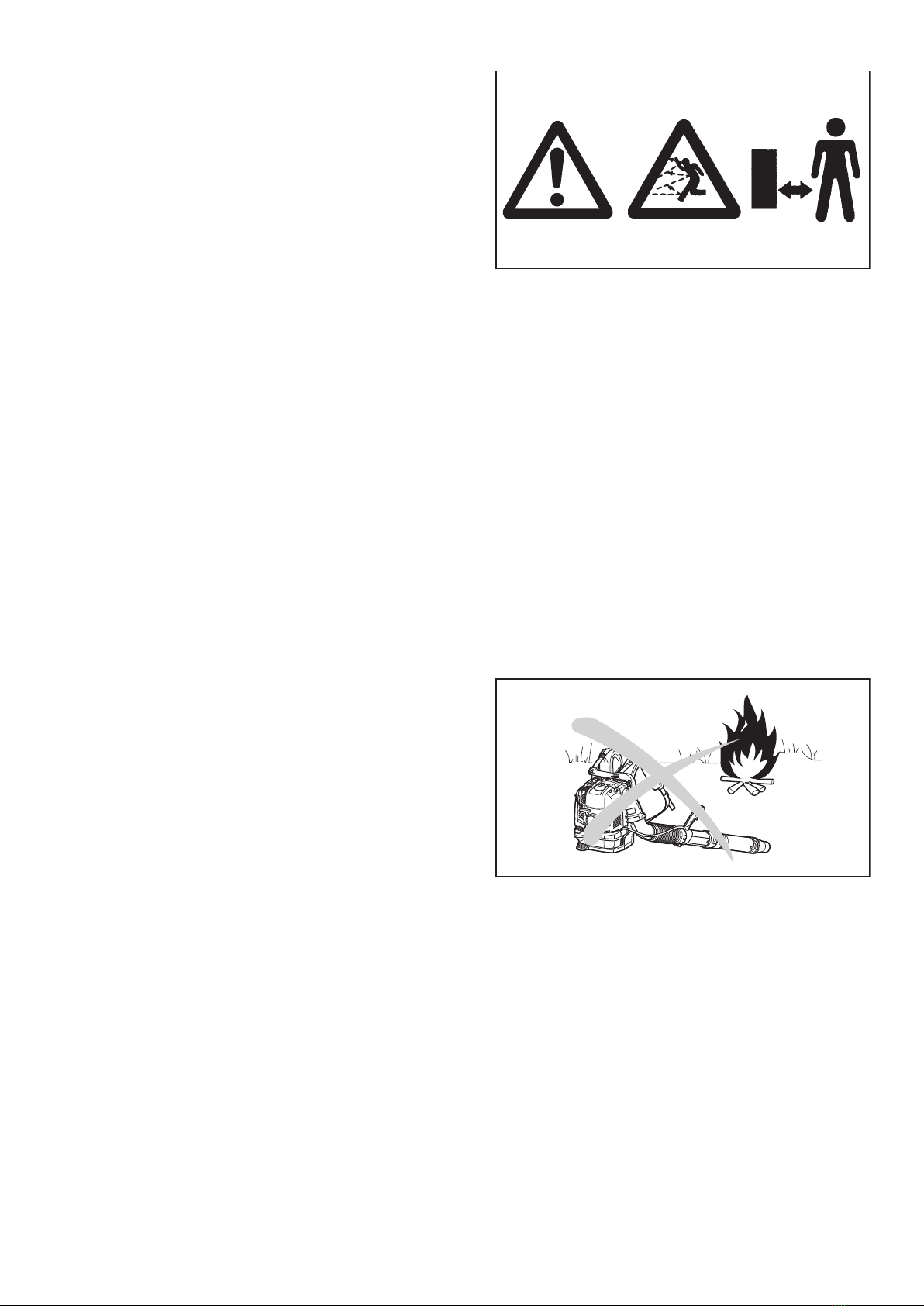
Proper eye protection is a must. Even though the discharge is directed
away from the operator, ricochets and bounce-backs can occur during
blower operation. (3)
Never operate a blower unless wearing goggles or properly tted safety
glasses with adequate top and side protection which comply with EN166
and regulations in your country.
To reduce the risk of injury associated with the inhalation of dust, use
face lter mask in dusty conditions.
Starting up the blower
Make sure that there are no children or other people within a working
range of 15 meters (5), also pay attention to any animals in the working
vicinity. Never use the blower in urban areas.
Before operating, always check that the blower is safe for operation:
Check the security of the throttle lever. The throttle lever should be
checked for smooth and easy action. Check for proper functioning of the
throttle lever lock. Check for clean and dry handles and test the function
of the l-O switch. Keep handles free of oil and fuel.
●
●
●
●
●
●
●
●
●
●
●
●
●
●
●
●
●
●
●
●
●
(1)
(2)
(3)
(5)
(4)
15 meters

4
5
Start the Blower only in accordance with the instructions. Do not use any
other methods for starting the engine (6).
Use the blower and the tools supplied only for applications specied.
Start the blower engine only after the entire tool has been assembled.
Operation of the tool is permitted only after all the appropriate accessories
are attached.
The engine is to be switched off immediately if there are any engine
problems.
When working with the blower, always wrap your ngers tightly around
the handle, keeping the control handle cradled between your thumb and
forenger. Keep your hand in this position to have your machine under
control at all times. Make sure your control handle is in good condition
and free of moisture, pitch, oil or grease.
Always ensure a safe, well-balanced footing.
Carry the blower properly on both shoulders during operation. Do not
carry the blower with only one shoulder strap. Otherwise personal injury
may result.
Operate the blower in such a manner as to avoid inhalation of the exhaust
gases. Never run the engine in enclosed rooms (risk of suffocation and
gas poisoning). Carbon monoxide is an odorless gas.
Always ensure there is adequate ventilation.
Switch off the engine when resting or leaving the blower unattended.
Place it in a safe location prevent danger to others, setting re to
combustible materials, or damage to the machine.
Never lay the hot blower onto dry grass or onto any combustible
materials.
All protective parts and guards supplied with the machine must be used
during operation.
Never operate the engine with a faulty exhaust mufer.
Shut off the engine during transport (7).
Position the blower safely during car or truck transportation to avoid fuel
leakage.
When transporting the blower, ensure that the fuel tank is completely
empty.
Carry the blower by its carry handle. Do not drag the blower by nozzle,
pipe or other parts.
When transport the blower, bent your knee and make sure you do not
damage your shoulder and lower back.
Refuelling
Shut off the engine during refuelling (7), keep well away from open ame
(8) and do not smoke.
Avoid skin contact with petroleum products. Do not inhale fuel vapor.
Always wear protective gloves during refuelling. Change and clean
protective clothing at regular intervals.
Take care not to spill either fuel or oil in order to prevent soil contamination
(environmental protection). Clean the blower immediately after fuel has
been spilt. Allow wet cloths to dry before disposing in properly, covered
container to prevent spontaneous combustion.
Avoid any fuel contact with your clothing. Change your clothing
immediately if fuel has been spilled on it (re hazard).
Inspect the fuel cap at regular intervals making sure that it stays securely
fastened.
Carefully tighten the locking screw of the fuel tank. Change locations to
start the engine (at least 3 meters away from the place of refuelling) (9).
Never refuel in closed rooms. Fuel vapors accumulate at ground level
(risk of explosions).
Only transport and store fuel in approved containers. Make sure stored
fuel is not accessible to children.
Do not attempt to refuel a hot or a running engine.
●
●
●
●
●
●
●
●
●
●
●
●
●
●
●
●
●
●
●
●
●
●
●
●
●
Resting
Transport
Refuelling
Maintenance
Tool Replacement
●
●
●
●
●
(7)
(6)
(8)
(9)
3 meters

4
5
Method of operation
Use the blower only in good light and visibility. Beware of slippery or wet
areas, ice and snow (risk of slipping) , and narrow space.
Always ensure a safe footing.
Never work on unstable surfaces or steep terrain.
Do not work from ladders or high places. Otherwise it may result in
personal injury.
To reduce the risk of personal injury, do not direct air blast towards
bystanders, since the high pressure of the air ow could injure eyes and
could blow small objects at great speed.
Never insert any foreign object into the air intake of the machine or into
the nozzle of the blower. It will damage the fan wheel and may cause
serious injury to the operator or bystanders as a result of the object or
broken parts being thrown out at high speed.
Pay attention to the direction of the wind, i.e., do not work against the
wind.
To reduce the risk of stumbling and loss of control, do not walk backward
while operating the machine.
Always shut off the engine before cleaning or servicing the unit or
replacing parts.
Take a rest to prevent loss of control caused by fatigue. We recommend
to take a 10 to 20-minute rest every hour.
Do not operate the machine near the windows, etc.
To reduce damage from vibration and/or damage to the ears, operate the
machine at low speed if possible and limit the time of operation.
Operate the machine only at reasonable hours. Do not operate the blower
in the morning or late at night when people might be disturbed.
It is recommended for using rakes and brooms to loosen debris before
blowing.
Before blowing, slightly dampen surfaces in dusty conditions or use
water mist sprayer if necessary.
Adjust the length of the blower nozzle so that the stream can work close
to the ground.
To reduce sound levels, limit the number of pieces of equipment used at
any one time.
After using blowers and other equipment, CLEAN UP! Dispose of debris in
trash receptacles.
Maintenance instructions
Be kind to the environment. Operate the blower with as little noise and
pollution as possible. In particular, check the correct adjustment of the
carburetor.
Clean the blower at regular intervals and check that all screws and nuts
are securely tightened.
Never service or store the blower in the vicinity of open ames, sparks,
etc. (11).
Always store the blower in a well-ventilated locked room and with an
emptied fuel tank.
Observe and follow all relevant accident prevention instructions issued by
the trade associations and by insurance companies. Do not perform any
modications to the blower as this will risk your safety.
The performance of maintenance or repair work by the user is limited to
those activities as described in this instruction manual. All other work is to
be done by Authorized Service Agents.
Use only genuine spare parts and accessories supplied by Makita.
Use of non-approved accessories and tools means increased risk of
accidents and injuries. Makita will not accept any liability for accidents
or damage caused by the use of any non-approved attachment or
accessories.
Never make modication on the equipment. It may cause dangerous
accidents or personal injury.
●
●
●
●
●
●
●
●
●
●
●
●
●
●
●
●
●
●
●
●
(10)
(11)

6
7
First Aid
In case of accident make sure that a well-stocked rst-aid kit is available
in the vicinity of the operations. Immediately replace any item taken from
the rst aid kit.
When asking for help, please give the following information:
Place of accident
What happened
Number of injured persons
Extent of injuries
Your name
●
●
●
●
●
(12)
For European countries only
EC Declaration of Conformity
We Makita Corporation as the responsible manufacturer declare that the following Makita machine(s):
Designation of Machine: Petrol Blower
Model No./ Type: EB7650TH, EB7650WH
Specications: see “TECHNICAL DATA” table
are of series production and
Conforms to the following European Directives:
2000/14/EC, 2006/42/EC
And are manufactured in accordance with the following standards or standardized documents:
EN15503
The technical documentation is kept by our authorized representative in Europe who is:
Makita International Europe Ltd.,
Michigan Drive, Tongwell, Milton Keynes, Bucks MK15 8JD, England
The conformity assessment procedure required by Directive 2000/14/EC was in Accordance with annex V.
Measured Sound Power Level: 110 dB
Guaranteed Sound Power Level: 111 dB
6. 8. 2013
Tomoyasu Kato
Director
Makita Corporation
3-11-8, Sumiyoshi-cho,
Anjo, Aichi, JAPAN

6
7
TECHNICAL DATA
Model EB7650TH EB7650WH
Throttle type Tube throttle Hip throttle
Mass (without blower pipe) (kg) 10.8 11.0
Dimension (without blower pipe L x W x H) (mm) 332 x 460 x 480 332 x 510 x 480
Air velocity
(with long pipe)
(with speed nozzle)
(m/s)
89
(with volume nozzle) 81
(with at nozzle) 86
(with short pipe)
(with speed nozzle) 90
(with volume nozzle) 81
(with at nozzle) 87
Air volume ow rate
(with long pipe)
(with speed nozzle)
(m3/minute)
17
(with volume nozzle) 19
(with at nozzle) 17
(with short pipe)
(with speed nozzle) 17
(with volume nozzle) 19
(with at nozzle) 17
Max. engine speed (with speed nozzle) (min–1)7,100
Idling speed (min–1)2,800
Engine displacement (cm3) 75.6
Fuel Automobile gasoline
Fuel tank capacity (cm3)1,900
Engine oil API grade SF class or higher, SAE 10W-30 oil
(automobile 4-stroke engine oil)
Engine oil volume (cm3)220
Carburetor (type) Diaphragm
Spark plug NGK CMR6A
Electrode gap (mm) 0.7 – 0.8
Vibration per
EN15503 2009
Right
handle
ahv eq
(with long pipe)
(with speed nozzle)
(m/s2)
2.5 2.7
(with volume nozzle) 2.3 2.3
(with at nozzle) 4.1 4.8
(with short pipe)
(with speed nozzle) 3.1 2.7
(with volume nozzle) 2.8 2.3
(with at nozzle) 3.7 5.1
Uncertainty K 2.2 3.0
Left
handle
(control
arm)
ahv eq
(with long pipe)
(with speed nozzle) 0.7
(with volume nozzle) 0.7
(with at nozzle) 0.9
(with short pipe)
(with speed nozzle) 0.8
(with volume nozzle) 0.7
(with at nozzle) 0.9
Uncertainty K 0.5
Sound pressure level average to EN15503: 2009 LPA eq dB(A) 100
Uncertainty K dB(A) 1.5
Sound power level average to EN15503: 2009 LWA eq dB(A) 110
Uncertainty K dB(A) 1.0
Notes:
Due to our continuing program of research and development, the specications herein are subject to change without notice.
Specications may differ from country to country.
●
●

8
9
DESIGNATION OF PARTS
1
2
3
4
5
6
8
32
32
7
7
910 11 12 14 15 16 17
19
18
1
2
3
4
5
6
8910 11 12
13
14 15 16 17
19
18
20
21
22
23
24
25
26
20
EB7650TH
EB7650WH
27 28 29
30
31
1. Shoulder strap 9. Oil cap 17. Air inlet net (at the bottom) 25. Stop switch
2. Spark plug cover 10. Mufer 18. Air cleaner cover 26. Control arm
3. Choke lever 11. Elbow 19. Bolt (of air cleaner cover) 27. Speed nozzle
4. Primer pump 12. Flexible pipe 20. Carry handle 28. Volume nozzle
5. Starter knob 13. Handle assembly 21. Stop control lever 29. Flat nozzle
6. Fuel tank cap 14. Swivel 22. Control handle 30. Long pipe
7. Fuel tank 15. Pipe (long/short) 23. Throttle trigger 31. Short pipe (optional
accessory)
8. Oil drain bolt 16. Nozzle 24. Throttle lever 32. Anti icing lever
Standard accessories may differ from country to country.●

8
9
ASSEMBLY INSTRUCTIONS
ASSEMBLY OF BLOWER PIPES
CAUTION:
Before performing any work on the blower, always stop the engine
and pull the spark plug connectors off the spark plug.
Always wear protective gloves!
Start the blower only after having assembled it completely.
Always wear protective gloves!
1. Insert the swivel (3) into the exible pipe (1) and tighten them with hose
band (2).
●
●
●
2. Install the control handle / handle assembly (4) onto the swivel and
tighten them with the clamp screw (5).
3. For tube throttle model
Insert the exible pipe to elbow (6) of the blower.
Attach the cable holder (7) between the hose band (8) and the elbow.
Tighten the cable holder, exible pipe and elbow with the hose band.
Set the control cable (9) onto the cable holder (7).
For hip throttle model
Insert the exible pipe to elbow (6) of the blower.
Tighten the exible pipe and elbow with the hose band (8).
4. Attach the long/short pipe (10) with the swivel. Turn the long/short pipe
clockwise to lock it into place.
Then attach the blower nozzle (11) with the long/short pipe. Turn the
blower nozzle clockwise to lock it into place.
5. Make sure all clamps are tight.
(1)
(2)
(3)
(5)
(4)
(10) (11)
(6) (8)
(7)
(9)
(7)

10
11
BEFORE STARTING THE ENGINE
1. Checking and Relling Engine Oil
1) Perform the following procedure, with the engine cooled down.
Otherwise skin burn may result.
Inspection: Put the blower on a at surface and remove the oil
cap.
Check the oil gauge (1). Make sure that the oil level is
within the upper (2) and lower (3) limit marks. If the oil
is not up to the 100 ml level (4), ll up with new oil.
Filling oil: Put the blower on a at surface and remove the oil
cap.
Fill the oil up to the upper limit of the oil level gauge.
2) On average, engine oil needs to be added after every 20 hours of
operation (every 10 – 15 refuellings).
3) Change the oil whenever it becomes dirty or signicantly changes
color. (Refer to “Replacement of engine oil” for the oil change
procedure and frequency.)
●
●
Recommended oil: Makita genuine oil or SAE10W-30 oil of API type SF grade or better (4 stroke motor oil for automobiles)
Oil capacity: Approximately 0.22 L (220 ml)
NOTE:
If the blower is not stored in an upright position, the oil may ow from the level gauge into the engine and give a false reading when checking the
oil level. This may result in inadvertently overlling whenever adding engine oil. Always store the blower in an upright position.
If the engine oil is exceeded, the oil may spill from the breather of the air cleaner and make surrounding parts dirty, or white smoke may appear
due to burning excessive oil.
Replacement of Oil “Oil cap”
Remove dust or dirt near the oil rell port, and detach the oil cap.
Keep the detached oil cap free of sand or dust. Otherwise, any sand or dust adhering to the oil cap may cause irregular oil circulation or wear on
the engine parts, which will result in troubles.
After relling oil
Wipe with a rag any spilled oil.
●
●
●
●
●
(1)
(2)
(4)
(3)

10
11
2. Fuel supply
WARNING:
When refuelling the unit, be sure to observe the following instructions to prevent ignition or re or personal injury:
Fuel supply must be made in a place free of re. Never bring the re (smoking, etc.) near the place of fuel supply.
Stop the engine and allow the engine to cool down before refuelling.
Refuel on at surface. Do not refuel on unstable or bad ventilated place.
Refuel in good light and visibility.
Refuel at open clear place.
Open the fuel tank cap slowly. The fuel may be spilled out by internal pressure.
Take care not to spill the fuel. Any spilled fuel must be wiped clean.
Carry out fuel supply in a well-ventilated place.
Handle the fuel with care.
Fuel sticking to the skin or entering an eye may cause allergies or irritation. When any physical abnormality is detected, consult the medical
specialist immediately.
DO NOT put oil in the fuel tank.
STORAGE PERIOD OF FUEL
Fuel should be used within a period of 4 weeks, even if it is kept in a special container in a well-ventilated and shaded area.
Otherwise, fuel may deteriorate in one day.
Storage of machine and rell tank
Keep the machine and tank at a cool place free from direct sunshine.
Never keep the fuel in a car.
FUEL
The engine is a four-stroke engine. Be sure to use an automobile gasoline (regular gasoline or premium gasoline).
Points for Fuel
Never use a gasoline mixture which contains engine oil. Otherwise, it will cause excessive carbon accumulation or mechanical troubles.
Use of deteriorated oil will cause irregular start-up.
When refuelling, stop the engine and wait for the engine to cool down.
REFUELLING METHOD
Loosen the tank cap a little to release the tank pressure.
Detach the tank cap, and refuel, discharging air by tilting the fuel tank so that the refuel port will be oriented upward. DO NOT ll fuel up to the
top of the tank.
After refuelling, securely tighten the tank cap.
If there is any aw or damage on the tank cap, replace it.
The tank cap wears out in course of time. Replace it every two to three years.
DO NOT put fuel in the oil ll port.
●
–
–
–
–
–
–
–
–
●
–
●
●
●
●
●
●
●
●
●
●
●

12
13
OPERATION
1. Starting
WARNING:
Never attempt engine start in a place where the fuel has been
supplied.
It may cause ignition or re. When starting the engine, keep a distance
of at least 3 m.
Exhaust gas from the engine is toxic. Do not operate the engine in a
poorly-ventilated place, such as in a tunnel, building, etc.
Operating the engine in the poorly-ventilated place may cause
poisoning by exhaust gas.
In case of detection of any abnormality in sound, odor, vibration after
starting, stop the engine immediately and carry out inspection.
If the engine is operated without attending such abnormality, an
accident may occur.
Do not touch hot engine cover. Otherwise skin burn may result.
Make sure that there are no fuel leakage before starting the engine.
Make sure that the engine stops when the stop switch is set to “O”
position.
1) When the engine is cold or after refuelling (cold start)
(1) Put the blower on a at surface.
(2) For tube throttle model
Set the stop control lever (1) to “I” position.
(2) For hip throttle model
Set the stop switch (1) to “I” position.
And make sure that the throttle lever (2) is set to low speed
position.
(3) Continue to push the primer pump (3) until fuel comes into the
primer pump.
In general, fuel comes into the carburetor by 7 to 10 pushes.
Even the primer pump is pushed excessively, an excess of
gasoline returns to the fuel tank.
(4) Lift the choke lever (4) to the closed position.
(5) Stump the pedal with your right foot, and hold the top of the unit
cover with left hand to prevent the engine from moving.
(6) Pull out slowly the starter handle till feeling compression.
Then pull it strongly.
Never pull the rope to the full extension.
Return the starter knob gently into the housing. Otherwise
released starter knob may hit your body or it may not rewind
appropriately.
(7) When the engine starts, down the choke lever to open position.
Open the choke lever fully when checking the engine
operation.
In cold temperature or when the engine is not warm enough,
never open the choke lever suddenly. Otherwise, the engine
may stop.
(8) Continue warm-up operation for 2 to 3 minutes.
(9) Warm-up is complete when quick engine acceleration from low
rpm to full throttle is felt.
●
–
●
–
●
–
●
●
●
●
●
●
●
●
●
(1)
EB7650TH EB7650WH
(2)
(1)
(4)
(3)
(6)

12
13
NOTE:
The engine may be damaged if the choke lever is moved further beyond
the “CLOSE” position.
If the engine res and stops, return this lever to the “OPEN” position and
pull the starter handle several times to start the engine again.
If the operator keeps pulling the starter handle several times with the
choke lever left in the “CLOSE” position, the engine may be difcult to
start because of ooding of the fuel.
In case of ooding of the fuel, remove the spark plug and pull the handle
several times rapidly to discharge any excess fuel. Dry the spark plug
electrode.
When the throttle valve (1) does not return to a position in contact with
the idling adjusting screw (2) even if the throttle lever is set to the low
speed, correct the control cable (3) catching state to ensure proper
return of the valve.
●
●
●
●
●
(1)
(2)
(3)
2) When the engine is warm (warm start)
(1) Put the engine on a at surface.
(2) Push the primer pump several times.
(3) Make sure that the choke lever is open.
(4) Stump the pedal with your right foot, and hold the top of the unit
with left hand to prevent the engine from moving.
(5) Pull slowly the starter handle till feeling compression. Then pull
it strongly.
(6) When the engine is difcult to start, open the throttle valve by
about 1/3.
2. Stopping
For tube throttle model
Release the throttle trigger (2) and then set the stop control lever (1) to
“O” position.
For hip throttle model
Set the throttle lever (1) to the low speed position to reduce the engine
speed. Then set the stop switch (2) to “O” position.
(1)
(2)
EB7650TH EB7650WH
O
O
(2)
(1)

14
15
ADJUSTMENT OF IDLING
CAUTION:
The carburetor is factory adjusted. Never adjust other than idling
adjusting. For other adjustments, ask Makita authorized service center.
Checkup of low-speed rotation
Set the low-speed rotation to 2,800 rpm (/min).
If it is necessary to change the rotation speed, regulate the idling
adjusting screw (1), with Phillips screwdriver.
Turn the adjusting screw to the right, and the engine speed will increase.
Turn the adjusting screw to the left, and the engine speed will drop.
●
●
●
PREVENTION FROM CARBURETOR ICING
CAUTION:
When environmental temperature is higher than 10°C, always return
the lever to normal (sun mark) setting. Otherwise the engine may be
damaged by overheating.
When the environmental temperature is low and humidity is high, water
vapor may freeze inside the carburetor and the engine drives unsteadily
(carburetor icing). Change the setting of the anti icing lever as follows if
necessary.
Environment temperature is higher than 10°C: Turn the lever to normal
position (sun mark).
Environment temperature is equal or lower than 10°C: Turn the lever to
anti-icing position (snow mark).
●
–
–
(1)

14
15
OPERATION METHOD
1. Adjusting Shoulder strap
Adjust the shoulder strap (1) to a length that is comfortable to work while
carrying the blower. To fasten (A) the strap, pull the end of the strap
downwards. To loosen (B) the strap, pull up the end of the fastener (2).
(1)
(2)
(A) (B)
(1)
(1)
2. Adjusting the control lever
For tube throttle model
Move the control handle along the swivel pipe to the most comfortable
position. Then tighten the control handle with the screw (1).
For hip throttle model
Move the handle assemble along the swivel to the most comfortable
position. Then tighten the handle with the screw (1).
Adjust the angle of the control arm for comfortable operation.
Pull the stabilizer strap (3) until there are no space left between your back
and the blower housing. To fasten (C) the strap, pull the end of the strap
downwards. To loosen (D) the strap, pull up the end of the fastener (4).
(3)
(4)
(C) (D)
The hip belt (optional accessory) enables the operator to carry the tool
more stably.

16
17
3. Blower Operation
1) While operating the blower, adjust the throttle trigger / throttle lever
so that the wind force is appropriate for the work location and
conditions.
2) Adjusting engine speed.
For tube throttle model
Engine speed increases by pulling the throttle trigger (1). To decrease
the engine speed, loosen the throttle trigger.
Adjusting engine speed with the cruise control function:
The cruise control function allows the operator to maintain a constant
engine speed without operating the trigger lever.
To increase the engine speed, turn the stop control lever (2) to high
speed.
To decrease the engine speed, turn the stop control lever to low
speed.
For hip throttle model
To increase the engine speed, turn the throttle lever (1) to high
speed.
To decrease the engine speed, turn the throttle lever to low speed.
TRANSPORTING AND STORING THE BLOWER
CAUTION:
When transporting the blower, be sure to stop the engine.
Do not sit or stand on the blower nor put an heavy object on it. It may
damage the tool.
Maintain the blower in an upright position whenever transporting or
storing.
Transporting or storing in a position that is not upright may cause oil to spill
inside the blower engine. This may result in oil leaks and white smoke from
burning oil, and the air cleaner may become dirty with oil.
Do not drag the blower when transporting. Otherwise the blower housing or
air inlet net may be damaged, and it may cause rust.
On the air inlet net there are ground contacts (1) which discharges
electrostatic to the ground.
●
*
(1)
EB7650TH EB7650WH
(2)
(1)
(1)

16
17
INSPECTION AND MAINTENANCE
CAUTION:
Before inspection and maintenance, stop the engine and allow it to cool down. Remove the spark plug and plug cap.
Otherwise the operator may suffer burn or serious injury due to an accidental start-up.
After inspection and maintenance, make sure that all parts are assembled. Then, proceed to operation.
1. Replacement of engine oil
Deteriorated engine oil will shorten the life of the sliding and rotating parts to a great extent. Be sure to check the period and quantity of
replacement.
CAUTION:
The engine main unit and engine oil still remain hot just after the engine is stopped. In replacement of oil, make sure that the engine main unit and
engine oil are sufciently cooled down. Otherwise, there may remain a risk of scald. Allow sufcient time after stopping engine for the engine oil
to return to the oil tank to ensure accurate reading of the oil level indicator.
If the oil lled above the limit, it may become dirty or may catch re with white smoke.
Interval of replacement: After rst 20 operating hours, followed by every 50 operating hours
Recommended oil: SAE10W-30 oil, API Classication SF Class or higher (4-stroke engine oil for automobile)
●
–
●
●
●
Oil Change Procedure
Please follow these steps when changing the oil:
(1) Set the blower down on a level surface.
(2) Put a waste oil container under the drainage hole (1) to catch
the oil as it drains out. The container should have a capacity of
at least 220 ml to be able to catch all of the oil.
(3) Loosen the oil drain bolt (2) to let the oil drain out. Be careful not
to allow oil to get on the fuel tank or other parts.
CAUTION:
Be careful not to lose the gasket (aluminum washer) (3). Put
the oil drain bolt (2) in a location where it will not accumulate
dirt.
(4) Remove the oil cap (4). (Removing the oil cap (4) allows the oil
to drain easily.)
CAUTION:
Be sure to set the oil cap (4) down in a location where it will
not accumulate dirt.
(5) As the level of the oil being drained decreases, tilt the blower
over on to the side with the drain so that the oil will completely
drain out.
(6) After the oil has completely drained out, tighten the oil drain bolt
(2) securely. If the bolt is not tightly fastened, this may result in
an oil leak.
CAUTION:
Do not forget to put the gasket (aluminum washer) (3) back
on when reattaching the drain plug.
(7) Adding oil during the oil change procedure is performed in the
same manner as the separately explained procedure for adding
oil whenever the level is insufcient. Always add oil by lling
from the opening under the oil cap.
(Specied oil level: Approximately 220 ml)
(8) After lling with oil, tighten the oil cap (4) securely to prevent oil
leaks.
●
●
●
(2)
(3)
(4)
(1)
Points in replacement of engine oil
Never discard replaced engine oil in garbage, earth or sewage ditch. Disposal of oil is regulated by law. In disposal, always follow the relevant
laws and regulations. For any points remaining unknown, contact Authorized Service Agent.
Oil will deteriorate even when it is kept unused. Perform inspection and replacement at regular intervals (replace with new oil every 6 months).
●
●

18
19
2. Cleaning of air cleaner
WARNING: INFLAMMABLES STRICTLY PROHIBITED
Interval of Cleaning and Inspection: Daily (every 10 operating hours)
(1) Loosen the bolts (1).
(2) Remove the air cleaner cover (2).
(3) Remove the element (3) and clean off any dirt from the element
with the brush.
Note:
The element is a dry type and should not get wet. Never wash
with water.
(4) Replace the element with a new one if it is damaged or very
dirty.
(5) Wipe off any oil that has come in to contact with the breather (4)
with a rag or cloth.
(6) Install the element in the air cleaner case.
(7) Attach the air cleaner cover and tighten the knob bolt.
NOTICE:
Clean the element several times a day, if excessive dust adheres to it.
If operation continues with the element remaining not cleared of oil, oil in
the air cleaner may fall outside, resulting in oil contamination.
3. Checking the spark plug
CAUTION:
Do not touch the spark plug while the engine is running. Otherwise
electrical shock may result.
Set the stop control lever/stop switch to OFF “O” position.
Check the spark plug cord regularly. If it is damaged or torn, replace it.
Otherwise electrical shock may result.
When removing the spark plug, clean the spark plug and cylinder head
rst, so that no dirt, sand, etc will enter the cylinder.
Remove the spark plug after the engine has cooled down in order to
avoid damaging the threaded hole in the cylinder.
Install the spark plug properly into the threaded hole. If installed at an
angle, the threaded hole in the cylinder will get damaged.
(1) Opening/closing the plug cover
To open (A) the plug cover (1), lift it and make a half turn of it. To
close (B) the plug cover, make a half turn of it, and press around
the dented part.
(2) Removing the spark plug
Use an attached box wrench to remove or install the spark
plug.
(3) Checking the spark plug
The clearance between two electrodes of spark plug is 0.7 to
0.8 mm. Adjust to the correct clearance when it is too wide or
too narrow.
Clean thoroughly or replace the spark plug if it has accumulated
carbon or contaminated.
(4) Replacing the spark plug
For replacement, use NGK-CMR6A.
●
●
●
●
●
●
●
●
●
(1)
(A) (B)
(1)
0.7 - 0.8 mm
(2)
(3)
(4)
(1)

18
19
4. Cleaning the fuel lter
Clogged fuel lter may cause difculty of start-up or failure of engine
speed increase.
Check the fuel lter regularly as follows:
(1) Remove the fuel tank cap (1), drain the fuel to empty the tank.
Check the tank inside for any foreign materials. If any, wipe
clean such materials.
(2) Pull out the fuel lter (2) with wire through the oil lling port.
(3) If the fuel lter surface is contaminated, clean it with gasoline.
The gasoline used for the cleaning must be disposed of
according to the method specied by each local authority.
Excessively contaminated lter must be replaced.
(4) After checking, cleaning or replacing, insert the fuel lter into the
fuel pipe and x it by the hose clamp (3). Reset the fuel lter in
the fuel tank and tighten rmly the fuel tank cap.
Make sure there is no damage on the fuel tank.
5. Inspection of bolts, nuts and screws
Retighten loose bolts, nuts, etc.
Check for fuel and oil leakage.
Replace damaged parts with new ones for safety operation.
6. Cleaning of parts
Keep engine clean by wiping down with a cloth rag.
Keep the cylinder ns free of dust or dirt. Dust or dirt adhering to the ns
will cause seizure.
Blowing air is taken in from the air inlet vent and the air inlet net (1). When
airow drops down during operation, stop engine and inspect the air
inlet vent and the air inlet net for any blockages. Clean it if necessary.
Check the air inlet net at the bottom. Remove the screw and the air inlet
net. Check if there are any blockages. Clean it if necessary.
Such a blockage may cause overheat and damage the engine.
WARNING:
Never use the blower without the net of the blower. Before each use,
check that the net is attached in place and is free from any damage.
7. Replacement of gaskets and packings
Replace gaskets and packings if the engine is disassembled.
Any maintenance of adjustment work that is not included and described in
this manual is only to be performed by Authorized Service Agent.
●
●
●
●
●
●
●
●
●
●
●
●
(2)
(3)
(1)
(1)
STORAGE
WARNING:
When draining the fuel, stop the engine and wait for the engine to cool down.
Failure to do so may cause burns or re.
CAUTION:
When you store the machine for a long time, drain all fuel from the fuel tank and carburetor, and keep it at a dry and clean place.
Drain fuel from the fuel tank and carburetor according to the following procedure:
(1) Remove the fuel tank cap, and drain fuel completely.
If there is any foreign materials remaining in the fuel tank, remove it completely.
(2) Pull out the fuel lter from the rell port using a wire.
(3) Push the primer pump until fuel is drained from there, and drain fuel coming into the fuel tank.
(4) Reset the lter to the fuel tank, and securely tighten the fuel tank cap.
(5) Then, continue to operate the engine until it stops.
(6) Remove the spark plug, and drip several drops of engine oil through the spark plug hole.
(7) Gently pull the starter handle so that engine oil will spread over the engine, and attach the spark plug.
(8) Keep the machine with its handle upside.
(9) Keep the drained fuel in a special container in a well-ventilated shade.
●
–
●

20
21
Fault location
Fault System Observation Cause
Engine not starting or
with difculty
Ignition system Ignition spark O.K. Fault in fuel supply or compression system, mechanical
defect
No ignition spark STOP-switch operated, wiring fault or short circuit, spark
plug or connector defective, ignition module faulty
Fuel supply Fuel tank lled Incorrect choke position, carburetor defective, fuel supply
line bent or blocked, fuel dirty.
Compression No compression when
pulled over
Cylinder bottom gasket defective, crankshaft seals
damaged, cylinder or piston rings defective or improper
sealing of spark plug
Mechanical fault Starter not engaging Broken starter spring, broken parts inside of the engine
Warm start problems Tank lled ignition spark
existing
Carburetor contaminated, have it cleaned
Engine starts but dies Fuel supply Tank lled Incorrect idling adjustment, carburetor contaminated
Fuel tank vent defective, fuel supply line interrupted, cable
or STOP-switch faulty
Insufcient performance Several systems may
simultaneously be
affected
Engine idling poor Air lter contaminated, carburetor contaminated, mufer
clogged, exhaust duct in the cylinder clogged
Operating time
Item Before
operation
After
lubrication
Daily
(10h) 30h 50h 200h Shutdown/
rest
Corresponding
Page
Engine oil Inspect/clean 10
Replace *1 17
Tightening parts (bolt,
nut) Inspect 19
Fuel tank Clean/inspect —
Drain fuel *3 19
Throttle trigger/
throttle lever Check function —
Stop control lever/
stop switch Check function 13
Low-speed rotation Inspect/adjust 14
Air cleaner Clean 18
Ignition plug / plug cord Inspect 18
Cooling air duct Clean/inspect 19
Fuel pipe Inspect 19
Replace *2 —
Fuel lter Clean/replace 19
Clearance between
air intake valve and air
discharge valve
Adjust *2 —
Oil tube Inspect *2 —
Engine overhaul *2 —
Carburetor Drain fuel *3 19
*1 Perform initial replacement after 20h operation.
*2 For the 200 operating hour inspection, request Authorized Service Agent or a machine shop.
*3 After emptying the fuel tank, continue to run the engine and drain fuel in the carburetor.
Other manuals for EB7650TH
4
This manual suits for next models
1
Table of contents
Languages:
Other Makita Blower manuals

Makita
Makita AS001G User manual

Makita
Makita BHX2500 User manual

Makita
Makita DUB361 Manual

Makita
Makita BBX7600 User guide

Makita
Makita PM7651H Manual

Makita
Makita DUB362 User manual

Makita
Makita PM001G User manual

Makita
Makita DUB184 User manual

Makita
Makita BHX2500 User manual

Makita
Makita DUB187 User manual

Makita
Makita BHX2500 Quick start guide

Makita
Makita UB003C User manual

Makita
Makita BHX2501 User manual

Makita
Makita UB141DZ User manual

Makita
Makita PM001G User manual

Makita
Makita DUB361 User manual

Makita
Makita DUB362 User manual

Makita
Makita PM7651H User guide

Makita
Makita PM7650HG User manual

Makita
Makita UB0800 User guide