Tigo TSB-20-US User manual
EI Battery Storage
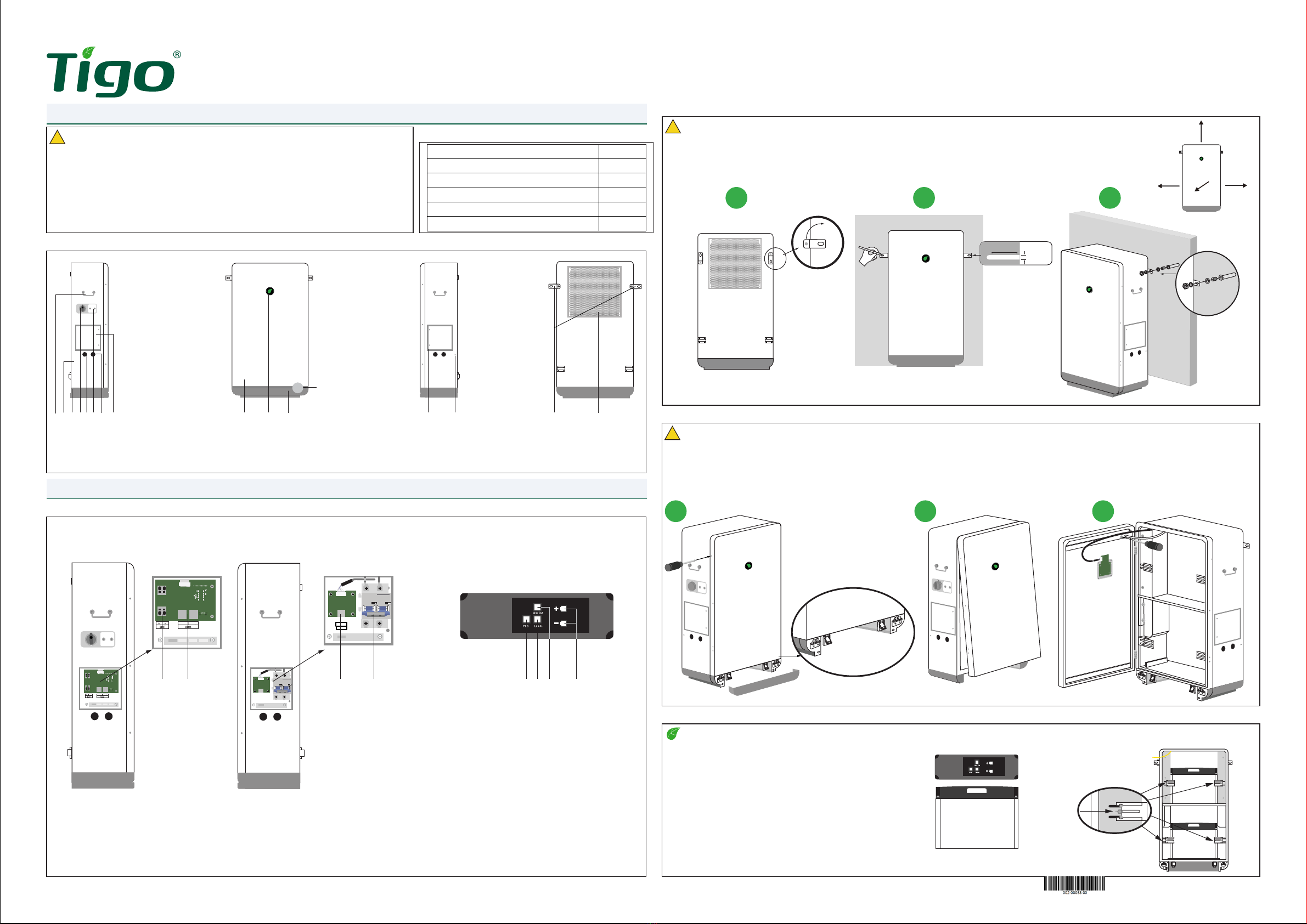
(1) Handle
(2) Battery enclosure
(3) Base
(4) Disconnect Switch
(5) DC Knockout
(6) Power Button
(7) Communications knockout
(8) Inverter connection wirebox
(9) Fro n t c ov e r
(10) LED indicator
(11) Base front cover
(12) Battery expansion wirebox
(13) GEC/bonding terminal
(14) Mounting tabs
(15) Heat sink
(1) Battery Power
(2) Battery Communication
(3) Extension Cabinet Communication
(4) Extension Cabinet Breaker
(5) PCS Terminal
(6) Link-In Terminal
(7) Link-Out Terminal
(8) Battery Ports
Door locking clips
(behind front panel)
1
1
2 3 456 7 8 9 10 11 12 13 14 15
1. General Information - specication
Note – The battery module’s power terminals face the right side of the enclosure. Install top battery before bottom battery packs.
Three battery modules per enclosure: 1 on top, 2 on bottom.
2.5 Install the battery modules
2.4 Removing the cover
Quick Start Guide - TSB-10/20-US
Pg 1 of 4
ATTENTION: READ FIRST
!
WARNING – the door has a grounding wire and display cable attached to the interior. Use caution and detach wires before
attempting to remove the door.
!
CAUTION - Ensure 12” clearance around all sides. Use appropriate hardware for the mounting surface.
For personal safety always wear appropriate PPE.
!
1.1 Package Contents
1.2 EI battery enclosure overview
Item Quantity
Battery Enclosure 1
Quick Start Guide 1
Safety-lock screws 6
Sleeve anchors 2
Wire ferrules 4
2.1 System overview
2. Installation
2.3 Mounting
1
1
3
3
2
2
1. This document is for quick guidance only. For details, please refer to the Energy Intelligence
(EI) Battery Storage Installation & Operations Manual.
2. Damage caused by failure to follow the contents of the EI Battery Storage Installation &
Operations Manual is not covered by the warranty.
3. Before installing the system check that the package contents are intact and complete against
the packing list. If any damage is found or any component is missing, contact your dealer.
1. Remove the bottom plate (11) and remove 3 screws from each side, 6 total. Unlatch the 2 front door locks from the bottom.
2. Tilt up and CAREFULLY swing door to the left, using caution to not pull ground or display wires.
3. Unscrew ground conductor and unplug display cable then set door aside.
1. The battery module serial numbers will be needed for the
commissioning. These are labeled on the module and the
box they shipped in.
2. Place the battery in the enclosure then slide the brackets
inward on each side of the battery and tighten the wingnut
to secure.
3. Repeat for batteries 2 and 3.
1. Rotate mounting tabs (14) 90° to face outward.
2. Mark holes for drilling. Drill 2” deep holes with an 8mm bit.
3. Insert anchor bolt sleeve. Position the battery enclosure mounting tabs anchor sleeve. Secure with washers and bolts.
2”
8 MM
≥12”
≥12”
≥12”
≥12”
Top
Front
ParallelINV
Parallel
INV CAN
COM
EI Battery Cabinet EI Battery Module
Top view
Left side Right side
2 3 4 5 6 7 8
PN: 002-00083-00 | Rev. 3.0 | 2022.11.09
EI Battery Storage
Quick Start Guide - TSB-10/20-US
Pg 2 of 4
If an external bonding point or grounding electrode conductor is
required, these may be connected to right side of the enclosure
at the GEC/Bonding terminal. This is not required for the
operation of the equipment.
3.5 GEC/Bonding terminal
3.3 Battery expansion - Parallel Connection
Note – This section applies to systems with multiple battery enclosures. The battery expansion cables/conductors should not exceed 6ft-7in.
If installing only one enclosure, skip this step.
Note – In the next section, Wiring the EI
Battery – Battery expansion, a communication
cable is routed between the two enclosures. At
the second enclosure this cable will terminate
at the Link-in terminal of battery module 4
(upper module/enclosure 2).
Wiring the battery modules (Battery enclosure 2)
If installing a second EI Battery enclosure complete
the power,Link-In and Link-Out connections as
described in the previous section.
EI Battery enclosure 1
Insert terminating cap in the Link-in terminal of battery
module 1 (upper module/enclosure 1).
EI Battery enclosure 2
The terminating cap is inserted in the CAN/COM
terminal in the Battery expansion wire box (12).
Note – IF INSTALLING ONLY ONE BATTERY ENCLOSURE, A terminating cap is required
in the COM port in the battery expansion wirebox (12).
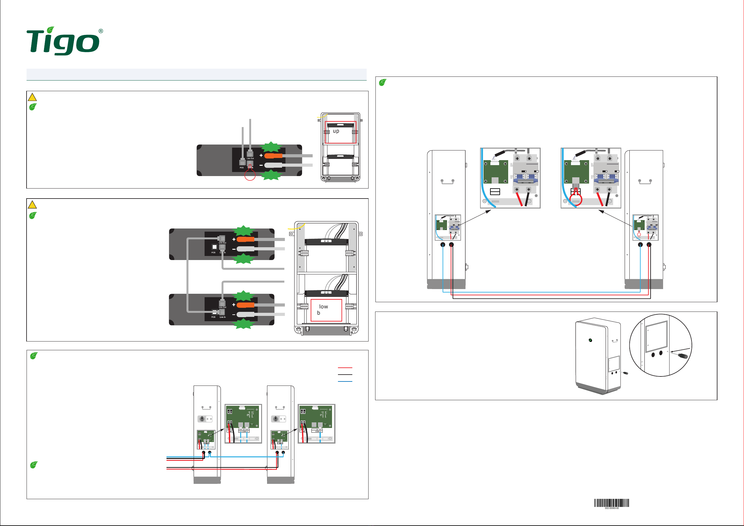
3.2 Wiring the lower batteries
!CAUTION – Do not reverse positive and negative of the battery input terminal.
Lower battery connections
1. Locate the cables labeled for the lower battery modules.
2. Connect provided lower inner battery link-out cable
(loose cable) to the lower inner battery terminal labeled
link-out.
3. Connect the opposite end of the lower inner battery
link-out cable from step 2 to the link-in terminal on the
lower outer battery.
4. Connect the lower inner battery link-in cable to the
lower inner battery link-in terminal.
5. Connect the lower inner battery + plug to the lower
inner battery red terminal labeled +.
6. Connect the lower inner battery - plug to the lower
inner battery black terminal labeled -.
7. Connect the lower outer battery + plug to the lower
outer battery red terminal labeled +.
8. Connect the lower outer battery - plug to the lower
outer battery black terminal labeled -.
9. Connect the outer lower battery link-out cable to the
link-out terminal on the lower outer battery.
10. Insert terminating cap in the CAN/COM terminal in the
battery expansion wiring box.
Note – The battery conductors and communications cables are labeled and located
inside the enclosure. CAREFULLY cut cable ties and connect as shown. When properly
installed a click will be heard.
3. Connecting the Batteries
3.1 Wiring the upper battery
!CAUTION – Do not reverse positive and negative of the battery input terminal.
Upper battery connections
1. Locate the cables labeled for the upper battery module.
2. Connect the PCS cable to the battery terminal labeled PCS.
3. Connect the upper battery link-out cable to the battery port
labeled link-out.
4. Connect the + plug to the red battery terminal labeled +.
5. Connect the - plug to the black battery terminal labeled -.
upper
battery
lower
battery
upper
battery
lower
battery
3.4 Battery expansion - Series Connection
Note – This section applies to systems with multiple battery enclosures. The battery expansion cables/conductors should not exceed 6ft-7in.
If installing only one enclosure, skip this step.
1. Using a Philips screwdriver, loosen 2 captive screws on the expansion wirebox (12) on the right side of each enclosure.
2. Install 2 conduits from the right side of enclosure 1 to the right side of enclosure 2 for the DC conductors and communication cable. Use appropriate
conduit ttings to provide a water-tight seal.
3. Prepare 2 DC conductors 6AWG and route through the conduit and one CAT5/6 with RJ45 connectors on each end.
4. Connect BAT-Expansion + from enclosure 1 to BAT-Expansion + of enclosure 2.
5. Connection BAT-Expansion - from enclosure 1 to BAT-Expansion - of enclosure 2.
6. Connect a communication cable from the Link Out port of Battery 3 (enclosure 1) to the Link In port of Battery 4 (enclosure 2).
7. Plug terminating cap into the COM port of enclosure 2.
Primary Secondary
CAN
COM
CAN
COM
CLICK
CLICK
CLICK
CLICK
CLICK
CLICK
Inner battery
Outer battery
Parallel
PV Parallel
PV
BAT+
BAT-
COM
Left Side
Primary Secondary
Parallel
PV Parallel
PV
PN: 002-00083-00 | Rev. 3.0 | 2022.11.09
EI Battery Storage
Quick Start Guide - TSB-10/20-US
Pg 3 of 4
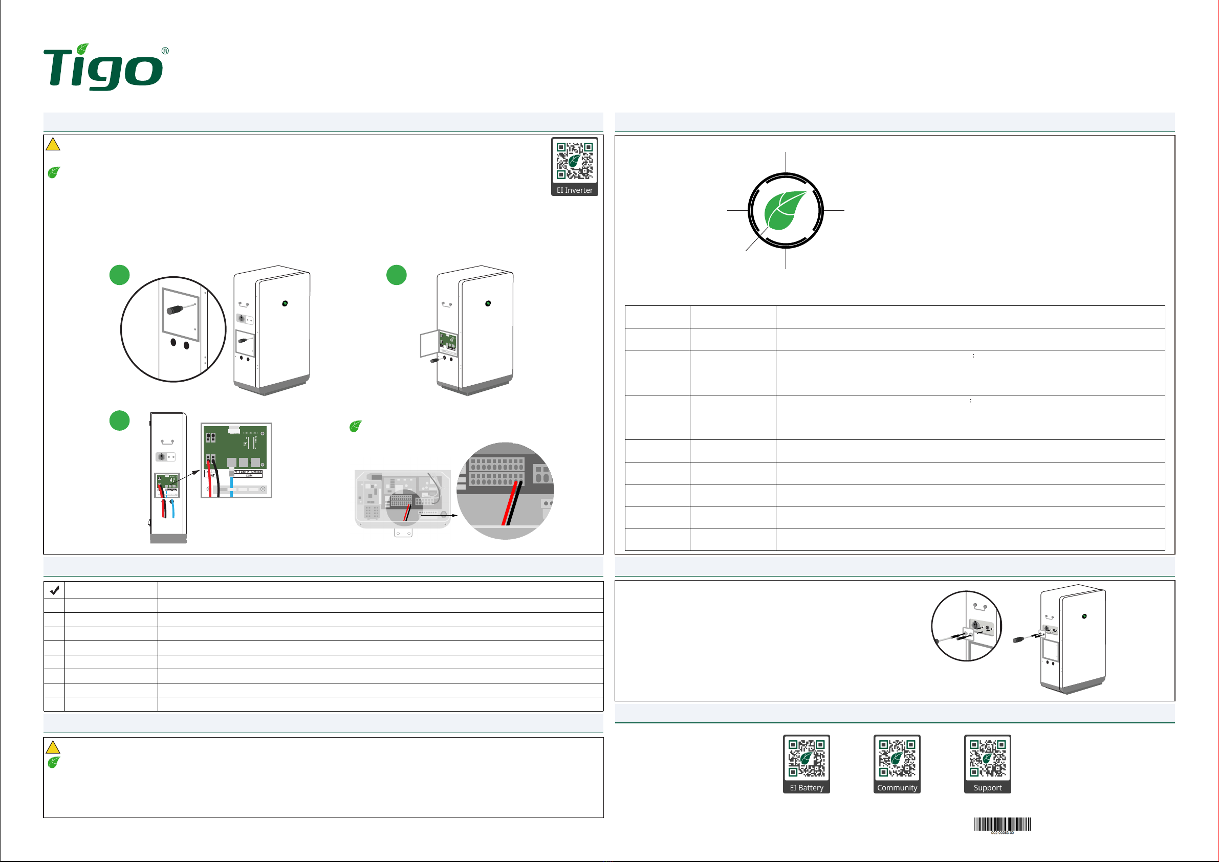
5. Pre-power checklist
6. Powering on the battery storage system
7. LED indicators
LED lights are displayed as follows in TSB-10/20-US different states:
A: Middle indicator (indicate status)
B: Ring indicator (indicate battery power)
B4
B1
A
B3 B2
Number Status LED light display
1Standby state Center leaf; ashing green (0.5 seconds on and 2 seconds off)
indicates the standby state. Ring indicator-refer to Discharge state.
2Charge state
Center leaf; green light is on. Ring indicator indicates
1. Power≤25%, LED B1 ashes, LED B2/3/4 are off;
2. Power≤50%, LED B1 is on, LED B2 ashes, LED B3/4 are off;
3. Power≤75%, LED B1/2 are on, LED B3 ashes, LED B4 is off;
4. Power>75%, LED B1/2/3 are on, LED B4 ashes.
3Discharge state
Center leaf green light is on. Ring indicator indicates
1. Power≤25%, LED B1 is on, LED B2/3/4 are off;
2. Power≤50%, LED B1/2 are on, LED B3/4 are off;
3. Power≤75%, LED B1/2/3 are on, LED B4 are off;
4. Power>75%, LED B1/2/3/4 are on.
4Alarm state Center leaf; green light ashes (0.5 seconds on and 0.5
seconds off, 0.5 seconds on and 2 seconds off). Ring indicator-refer to Discharge state.
5Fault state Center leaf; red light ashes (1 second on and 1 second
off). Ring indicator-refer to Discharge state.
6Upgrade state Center leaf; yellow light ashes(1 second on and 1 second off) indicates the upgrade state. Ring
indicator-refer to number 1.
7Manual forced power
on
Center leaf; green light ashing (0.1 seconds on and 0.1
seconds off) . Ring indicator-refer to Discharge state.
8Manual forced
shutdown
Center leaf; red light ashing (0.1 seconds on and 0.1 seconds off). Ring indicator-refer to Discharge
state.
Note – All other components of the EI Battery Storage system, including the energy meter must be installed for the system to operate.
!CAUTION – For personal safety always wear appropriate PPE.
8. Forced start/shutdown
Check Item Acceptance Criteria
Communications cable The communications cable is labeled and properly connected to both the inverter and battery communications terminals.
Battery power conductors The battery power conductors are labeled and properly connected to the inverter and battery terminals.
GEC/bonding If required, the GEC/bonding conductor is properly connected.
Expansion wiring If multiple batteries installed, BAT-Expansion+/BAT-Expansion- conductors and communications cable are properly connected.
Conduit connections All conduit attachments are sealed and bonded, when necessary.
Unused conduit openings Any unused conduit openings are tted with waterproof caps (provided) or left unopened.
Disconnect switches The BAT-switch and all other switches connecting to the EI Battery are OFF.
Installation environment An appropriate installation space had been chosen and the environment is left clean and accessible.
9. Your Customer Service Contact
Tigo Energy, Inc.
655 Campbell Technology Pkwy
Campbell, CA 95008
T: +1 408 402 0802
https://support.tigoenergy.com/
1. Turn ON the BAT-switch in the Inverter connections wirebox (8).
2. If multiple batteries installed, turn on the BAT-Expansion breaker in the Battery expansion wirebox (12). Otherwise, skip this step.
3. Turn on the inverter, while waiting 10 seconds for the inverter to send the wake-up signal observe the LED indicator of the battery enclosure. Conrm the
battery system enters the discharge state (center leaf is lit).
4. The battery storage system has been successfully started.
To force start or shutdown the EI Battery:
1. Using a Philips screwdriver, remove the screws from the cover of
the forced start power button (6).
2. Press and hold the button for 10 seconds until:
1. OFF: The center leaf changes from green to red and begins
ashing quickly (0.1s on/off)
2. ON: The center leaf begins ashing green (0.1s on/off).
3. After the forced start/shutdown is successful, reinstall the cover.
8. Forced start/shutdown
4. Connecting the inverter
Note – This section corresponds to section 3.7 and 4.2 in the EI Inverter Quick Start Guide.
Reference that document by scanning the QR code.
Note – The opposite end of the battery conductors
are connected in the inverter wirebox as shown.
!CAUTION – Risk of electric shock! Ensure the inverter and battery cabinet are completely powered off when these
steps take place. Make sure to connect the battery inverter first and then connect the communications cable to the
inverter.
1 2
4
1. Loosen the two captive screws on the left side of the battery enclosure’s inverter connection wirebox (8).
2. Remove the two waterproof knockouts (5), (7) at the bottom of the left side of the enclosure. Connect two conduits from the battery
enclosure to the inverter. Use appropriate water-tight ttings.
3. Prepare two conductors, 10-8AWG with wire ferrules and route through the conduit.
4. Verify the BAT-switch is in the OFF position, and connect the conductors as follows:
1. Insert the battery conductors into the terminals of BAT+ and BAT- (EI Inverter Quick Start Guide 3.7).
2. Insert the RJ45-CAT5/6 communications cable into the INV terminal (EI Inverter Quick Start Guide 4.2).
5. Once complete, replace the wirebox covers and the enclosure cover by reversing the steps of section 2.4
PN: 002-00083-00 | Rev. 3.0 | 2022.11.09

EI Battery Storage
Quick Start Guide - TSB-10/20-US
Pg 4 of 4
Four Battery Cabinet WiringTwo Battery Cabinet Wiring
UpperBattery
LinkOut
LinkIn
PCS
Lower Inner Battery
LinkOut
LinkIn
PCS
Lower Outer Battery
LinkOut
LinkIn
PCS
INV
Parallel
CAN
UpperBattery
LinkOut
LinkIn
PCS
Lower Inner Battery
LinkOut
LinkIn
PCS
Lower Outer Battery
LinkOut
LinkIn
PCS
INV
Parallel
UpperBattery
LinkOut
LinkIn
PCS
Lower Inner Battery
LinkOut
LinkIn
PCS
Lower Outer Battery
LinkOut
LinkIn
PCS
INV
Parallel
UpperBattery
LinkOut
LinkIn
PCS
Lower Inner Battery
LinkOut
LinkIn
PCS
Lower Outer Battery
LinkOut
LinkIn
PCS
INV
Parallel
RJ45
Connector
RJ45
Connector
RJ45
Connector
RJ45
Connector
+
-BAT
+
-BAT
+
-
Expansion
CAN
+
-
Expansion
CAN
+
-
Expansion
CAN
+
-
Expansion
BAT 1
BAT 2
BAT 3
BAT 4
Toinverter
Toinverter
Legend:
Cable included in cabinet:
Black – CAT5 cable
Installer made cables:
Blue – CAT5 cable
Yellow – 8 or 10 AWG cables
Green –6AWG cables
UpperBattery
Link Out
LinkIn
PCS
Lower Inner Battery
Link Out
LinkIn
PCS
Lower Outer Battery
Link Out
LinkIn
PCS
INV
Parallel
CAN
UpperBattery
Link Out
LinkIn
PCS
Lower Inner Battery
Link Out
LinkIn
PCS
Lower Outer Battery
Link Out
LinkIn
PCS
INV
Parallel
RJ45
Connector
RJ45
Connector
+
-BAT
+
-BAT
+
-
Expansion
CAN
+
-
Expansion
BAT 1
BAT 2
Toinverter
Toinverter
RJ45
Connector
RJ45
Connector
Legend:
Cable included in cabinet:
Black – CAT5 cable
Installer made cables:
Blue – CAT5 cable
Yellow – 8 or 10 AWG cables
PN: 002-00083-00 | Rev. 3.0 | 2022.11.09
This manual suits for next models
1
Popular Storage manuals by other brands

HP
HP Surestore Disk Array 12h - And FC60 Advanced user's guide

Samsung
Samsung SpintPoint M8-DVR product manual

Gladiator
Gladiator MODULAR BAMBOO STORAGE BENCH Assembly instructions

Medion
Medion LIFE P89655 instruction manual

iStorage
iStorage diskGenie user manual

NetApp
NetApp DiskShelf14mk4 FC Hardware and service guide


