Timotion PL600H User manual

FOR RESIDENTIAL
USER MANUAL
SLIDING GATE OPENERS
PL600H / PL1000H 24V DC MOTOR

Applicant: Powertech Automation Inc.
Manufacturer: Timotion Technology Co., Ltd.
Address: Shiyong Minying Industrial Zone, Hengli Town, DongGuan City, GuangDong, China
Model: PL600H, PL1000H, PR-2
1. Certificate of conformity of a product with the essential requirements art. 3.2 of the R&TTE Directive 1999/5/EC.
2. The above product has been tested with the listed standards and in compliance with the European Directive LVD
2006/95/EC.
3. The submitted sample of the above product has been tasted for CE marking according to the following European Directives:
2006/42/EC Machinery Directive.
Comply with the following Standards:
EN 301489-1 V1.8.1: 2008
EN 301489-3 V1.4.1: 2002
EN 300220-1 V2.1.1: 2006
EN 300220-2 V2.1.2: 2007
EN 60335-1: 2002+A11:2004+A1:2004+A12:2006+A2:2006+A13:2008
EN 60335-2-103: 2003
EN 62233: 2008
EN 12445: 2001
EN 12453: 2001
And also declare that the machinery may not be put into service until the machine, which will be integrated or become one of
the components, and announced to comply with the provisions as the required.
David Lan
(Deputy Managing Director)
Taiwan, Aug 23, 2013
Declaration of Conformity

INSTRUCTIONS PL600H/ PL1000H SLIDING GATE OPENER USER MANUAL 1
INDEX
1. Warnings
2. Installation
2.1 Standard Installation Demonstartion
2.2 Description of Device
2.3 Dimension of Device
2.4 Installation of Motor Gear and Gear Rack
2.5 Checking for Installation
2.6 Emergency Release
3. Setup and Function Setting
3.1 Wire Connection
3.2 Transmitter Memorization and Erasing Process
3.3 System Learning, Reset Process and LED Display
3.4 Programmable Function Settings
3.5 Programmable Functions of LED Display
3.6 Operations for Function Settings
3.7 The logic of gate movements
3.8 Backup Battery
4. Testing
5. Maintenance and Disposal
5.1 Maintenance
5.2 Disposal
6. Additional Information
6.1 Adding or Removing Device
6.2 Troubles Shooting
7) Technical Characteristics
7.1 Techanical Data Sheet Of Series
7.2 PH-2 Photocell Data Sheet
7.3 PR-2 Transmitter Data Sheet
7.4 PF-1 Flashing Light Data Sheet
7.5 PRB-1 External Receiver Box Data Sheet
8. Additional Information
8.1. PHOTOCELL INSTALLATION GUIDE
8.2 Wire Connection and Setting of PRB-1 External Reciever Box
8.3 Channel Transmitter Operation
P. 2
P. 3
P. 3
P. 3
P. 4
P. 4
P. 5
P. 5
P. 6
P. 6
P. 7
P. 7
P. 8
P. 8
P. 9
P.10
P.10
P.10
P.10
P.10
P.10
P. 11
P. 11
P. 11
P. 11
P. 11
P.12
P.12
P.12
P.12
P.12
P.12
P.13
P.14

2INSTRUCTIONS PL600H/ PL1000H SLIDING GATE OPENER USER MANUAL
1) Warnings
Please read this instruction manual carefully before the
installation of gate-automated system.
This manual is exclusively for qualified installation
personnel. Powertech Automation Inc. is not responsible for
improper installation and failure to comply with local
electrical and building regulations.
Keep all the components of PL600H/ PL1000H system and
this manual for further consultation.
In this manual, please pay extra attention to the contents
marked by the symbol:
Be aware of the hazards that may exist in the procedures
of installation and operation of the gate-automated
system. Besides, the installation must be carried out in
conformity with local standards and regulations.
If the system is correctly installed and used following all
the standards and regulations, it will ensure a high degree
of safety.
Make sure that the gates work properly before installing
the gate-automated system and confirm the gates are
appropriate for the application.
Do not let children operate or play with the
gate-automated system.
Do not cross the path of the gate-automated system when
operating.
Please keep all the control devices and any other pulse
generator away from children to avoid the gate-automated
system being activated accidentally.
Do not make any modifications to any components except
that it is mentioned in this manual.
Do not try to manually open or close the gates before you
release the gear motor.
If there is a failure that cannot be solved and is not
mentioned in this manual, please contact qualified
installation personnel.
Do not use the gate-automated system before all the
procedures and instructions have been carried out and
thoroughly read.
Test the gate-automated system weekly and have
qualified installation personnel to check and maintain the
system at least every 6-month.
Install warning signs (if necessary) on both sides of the
gate to warn the people in the area of potential hazards.

2.1 Standard Installation Demonstration
1. 24V DC sliding motor
2. Transmitter
3. Safety photo sensor
4. Flashing light
a. Operation gear
b. Limit switch device
c. 24Vdc motor
d. Back-up batteries (Optional)
e. Release device
f. Control panel
g. Terminals of devices
2) Installation:
3
4
2
3
e
f
g
a
b
c
d
2.2 Description of Device
INSTRUCTIONS PL600H/ PL1000H SLIDING GATE OPENER USER MANUAL 3
1
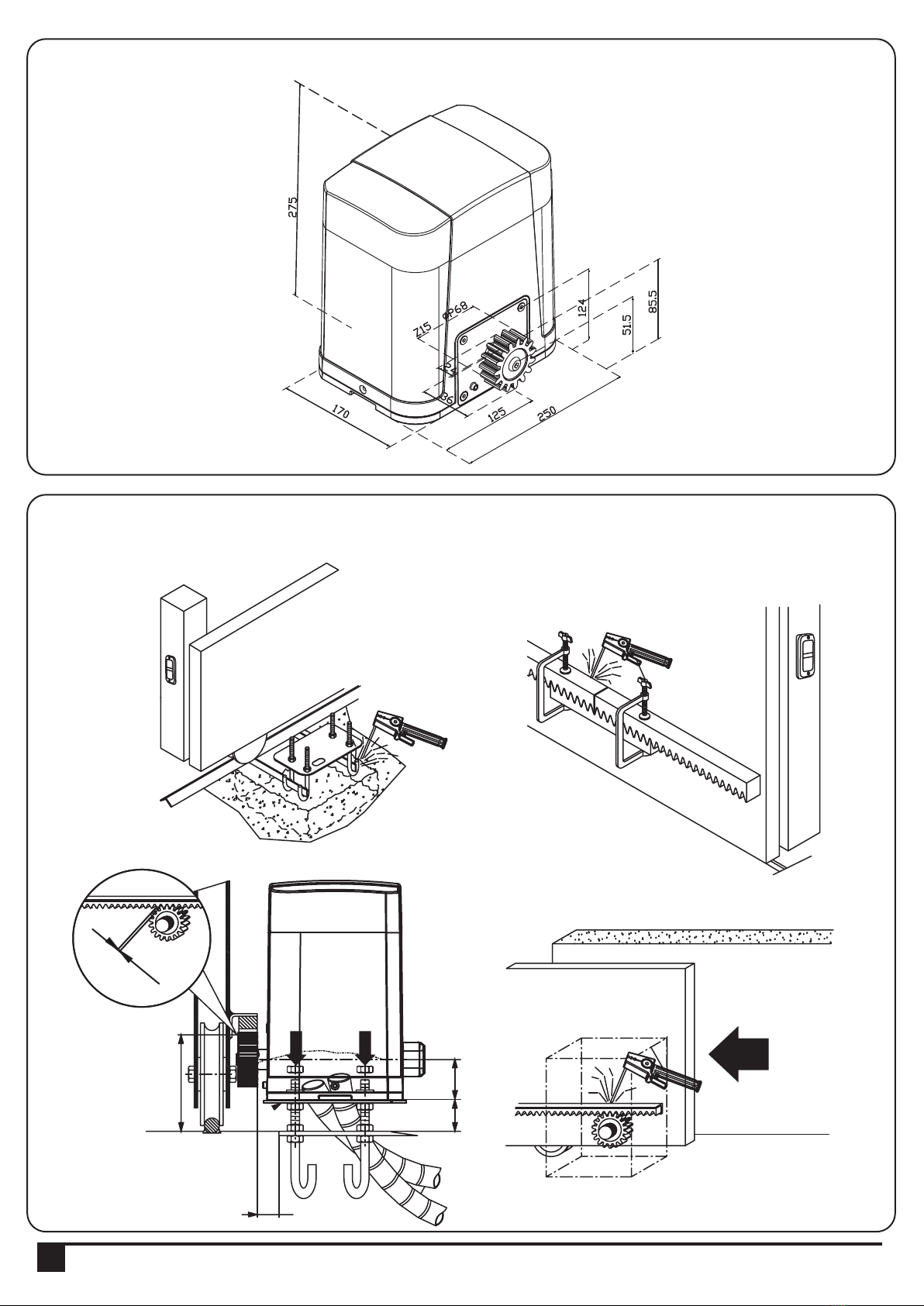
2.3 Dimension of Device
2.4 Installation of Motor Gear and Gear Rack
>100
25
50>25
1~2m
4INSTRUCTIONS PL600H/ PL1000H SLIDING GATE OPENER USER MANUAL

2.5 Checking for Installation
2.6 Emergency Release
In the case of power failure for emergency release of the motor, please follow the procedure
as below:
Step1. Push the lid of release chamber and move rightward
Step2. Insert the key and turn counterclockwise to unlock the device.
Step3. Turn counter-clockwise of the bar to release the motor
To restore the automation, simply reverse the above procedure.
Step1. Step2. Step3.
NO OK
DXSX
INSTRUCTIONS PL600H/ PL1000H SLIDING GATE OPENER USER MANUAL 5

3.1. Wire Connection
3) Setup and Function Setting:
If the LED display is in normal performing refer to “4.2.1”, you can control the gate by either transmitters or the button
on the board: “UP”-clockwise moving, “SET”- stop and “DOWN”- Counterclockwise moving.
6
6 7 9
9
6 8 9
6 9
10 11
PPB-1
PPB-1, PKS-1:
PKS-1
SW1
SW3
SW4
SW5
3 4
PF-1
PF-1
AC INPUT
12345678910
1
23456
AC INPUT
1234567891011
1
23456
6INSTRUCTIONS PL600H/ PL1000H SLIDING GATE OPENER USER MANUAL
LED1 Photocells
LED2 Photocells
LED3 RF Learn
AC INPUT
1234567891011121314
1
23456
1 2 3 4 5 6 7 8 9 10 11 12 13 14
Close
Stop
GND
Pb
Ph+
Ph2
Ph1
GND
EXT-
EXT+
GND
+13V
Light
Open
AC INPUT
1234567891011
1
23456
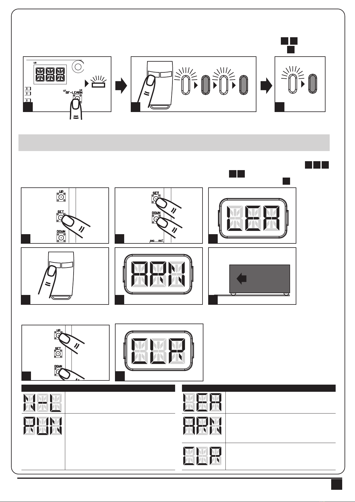
3.2 Transmitter Memorizing and Erasing Process
3.3 System Learning, Reset Process, and LED Display
(1) To Complete the System Learning:
Step1: Press “SET”; then press “SET” + “DOWN” for 3 seconds, and the LED display shows “LEA”
Step2: Press left button (A) on time, the LED display should show “ARN”
Step3: The gate goes to Auto-learning, please wait for the learning process to be completed
(2) To Reset Factory Setting:
Press UP and DOWN for 3 seconds, and the LED display shows “CLR”
(1) Transmitter Memorizing: Press “RF Learn” button for 2 seconds, and the LED3 is on; then press the transmitter
left button (A); the LED3 will blink twice and then be off. The transmitter learning is completed.
(2) Erasing Memory: Press "RF Learn" button for 5~6 seconds as LED3 is on, then wait for LED3 off.
LED 3
2 Sec
LED 3
blink twice LED 3 OFF
1 3
121314
LED1
LED2
LED3
ON
OFF
Press
1~3 Sec
Press
3 Sec
Push
1 2 3
4 5 6
14
LED1
LED2
LED3
ON
OFF
234567891011121314
LED1
LED2
LED3
ON
OFF
Push
3 seconds
12
LED Display Programmable Functions LED Display Programmable Functions
“N-L”: The PL600H/ PL1000H system learning “LEA”: Enter learning mode and then wait for
learning instructions.
“CLR”: Reset Factory Setting.
“ARN”: The system learning is in progress.
The Auto-learning process of gate moving:
“Gate open to the end- stop close to the
end- stop.”
“RUN”: The PL600H/ PL1000H system is in
normal operation To program, press SET
button for 3 seconds, when the LED display
change from RUN to F1, press UP or DOWN
to change function settings (F1 to FA). Then
press SET to enter the sub function within
each group, press UP or Down to select sub
functions and press SET for confirmation.
! CAUTION: Before proceeding to system learning, the transmitter memorizing process has to be completed.
INSTRUCTIONS PL600H/ PL1000H SLIDING GATE OPENER USER MANUAL 7
1
1 2
4 5
6
3
2
3
14
LED1
LED2
LED3
ON
OFF
AB
AB
2
8INSTRUCTIONS PL600H/ PL1000H SLIDING GATE OPENER USER MANUAL
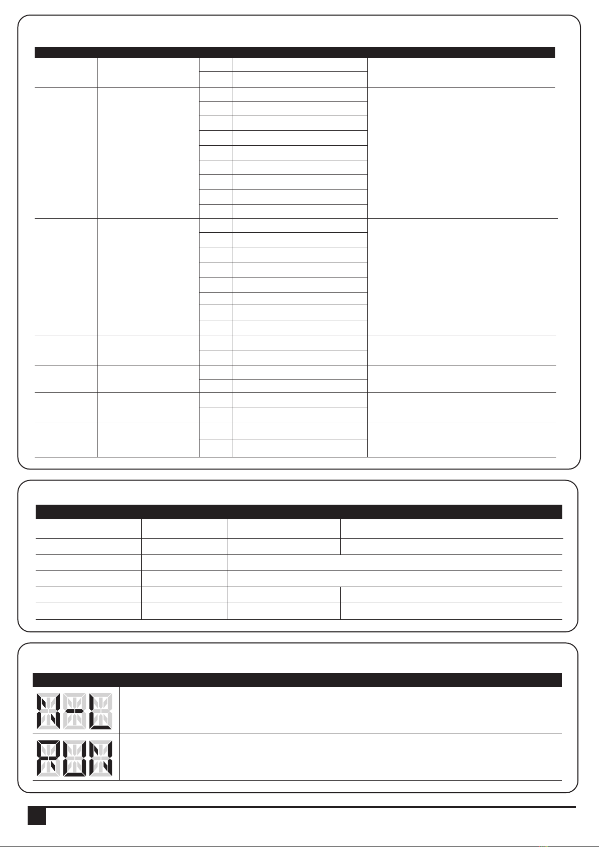
3.4 Programmable Function Settings
Options of Gate
Opening direction
Automatic Closing
Over current setting
Photocell 1 function
Photocell 2 function
Stop connector function
Length of gate
F1
F2
F3
F4
F5
F6
F7
F1-0
F1-1
F2-0
F2-1
F2-2
F2-3
F2-4
F2-5
F2-6
F2-7
F2-8
F3-1
F3-2
F3-3
F3-4
F3-5
F3-6
F3-7
F3-8
F4-0
F4-1
F5-0
F5-1
F6-0
F6-1
F7-1
F7-2
Clockwise Opening
Counter clockwise Opening
No automatic closing
5 seconds
15 seconds
30 seconds
45 seconds
60 seconds
80 seconds
120 seconds
180 seconds
2A
3A
4A
5A
6A
7A
8A
9A
Close
Open
Close
Open
Close
Open
F7-1: Normal length of gate
F7-2: Short length of gate (like 1.5M)
1. The function can adjust the direction of gate opening.
2. The factory setting is "F1-1".
1. This function can cause the gate toclose automatically
after the paused time.
2. The factory setting is"F2-2”: 15 Secs as the pause time.
1. The function can adjust the running force of motor to
be compatible with the gate weight.
2. The factory setting is "F3-5".
1. The factory setting is "F4-0".
1. The factory setting is "F5-0".
1. The factory setting is "F6-0".
1. The factory setting F7-1
LED Display Definition Function Value Description
Gate Status
Closed
Open
Stop during moving
Closing
Opening
Photocell 2
Stop opening
No effect
Stop opening
No effect
Closes the leaf
Photocell 1
No effect
Open
No effect
Reloads automatic closing time
Reloads automatic closing time
Photocell 1/ Photocell 2
Stop opening
Locks and, on release, reverses to open
Locks and, on release, continues opening
The reactions of the photocells when detecting obstacles
3.5 Programmable Functions of LED Display
LED Display Programmable Functions
“N-L”: The PL600H system learning is not done.
“RUN”: The PL600H system is in normal performing.
● Photocell function:

INSTRUCTIONS PL600H/ PL1000H SLIDING GATE OPENER USER MANUAL 9
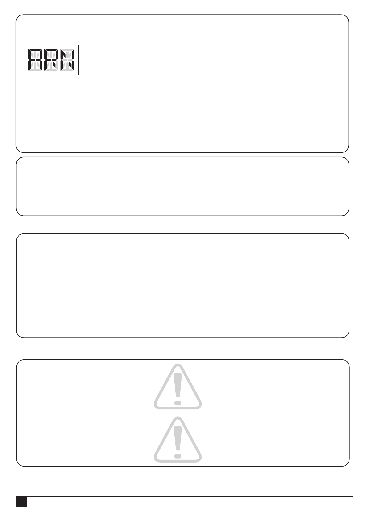
LED Display Programmable Functions
“LEA”: Enter learning mode and then wait for learning instructions.
The operation of gate learning:
(1). Press “SET” one time; then press “SET” + “DOWN” for 3seconds, and the LED display
shows “LEA” ; and then press the transmitter (A) button one time. After 1~3seconds, the LED
display shows “ARN”
“ARN”: The system learning is in progress.
The Auto-learning process of gate moving: move at low speed“Gate open to the end- stop
close to the end- stop.
For exmple: How to set the function “F1-0”; the steps are following:
(1) Press the “SET” button for 3seconds then releases it, and the
system enters the first option. The LED will display “F1” (*) as the
right hand-side picture.
(*) If you would like to enter “F2” function or others as the first option,
please press the “UP” button to adjust F2~F8 until you get “F2”.
1.
3.6 Operations for Function Settings
Step Operations LED Display after the Step
(2) After completing the operation (1), then press the “SET” button
again, you will enter the second option as the right hand-side picture.
And you will see the third number for the second option.
(3) Continually press the “Down” button until you search the function
“0” (**) of F1 as the right hand-side picture. “F1-0” is set completely.
(**) If you would like to set one of functions “0 ~ 8” as the second
option, please press the “UP” or “Down” button to adjust it.
(4) If you would continue setting up the next functions, please press
“SET” to return the first option, like F1 or F2 or F3…or F8.
For example, after complete “F1-0” setting. You would continue
setting “F2-5”, please press “SET” to return the formal option. The
LED display shows the first two numbers as as the first option as the
right hand-side picture, “F1”. And then follow the operation (*) and (2)
~ (3) until you get “F2-5” as the right hand-side picture. “F2-5” is set
completely.
After setting all functions you need, then wait for 10seconds, the LED
will display “RUN”. And you can use transmitter to operate the gate.
2.
3.
10 INSTRUCTIONS PL600H/ PL1000H SLIDING GATE OPENER USER MANUAL
1. When gate moves in the first time, the gate will move at middle speed: ’’gate open to the end-stop, close to the end stop”.
3.7 The logic of gate movements
4) Testing
Make sure the notices included in chapter 1 “WARNINGS” have been carefully observed.
● Release the gearmotor with the proper release key.
● Make sure the gate can be moved manually during opening and closing phases with a force of max. 390N
(40 kg approx.)
● Lock the gearmotor.
● Using the Key selector switch, push button device or the radio transmitter, test the opening, closing and stopping
of the gate and make sure that the gate is in the intended direction.
● Check the devices one by one (photocells, flashing light, key selector, etc.) and confirm the control unit recognizes
each device.
● Measure the impact force according to EN 12445 standard. If “motor force” control is used to support the system
for the reduction of the impact force, try to find the adjustment which offers the best results.
5) Maintenance and Disposal
The maintenance operations must be performed in strict compliance with the safety directions provided in the manual
and according to the applicable legislation and standard.
In order to have good and safety performances, test the gate-automated system weekly and have qualified
installation personnel to check and maintain the system at least every 6-month.
5.1 Maintenance
Some electronic components and the batteries may contain polluting materials; do not pollute the environment. Make
sure the recycling or disposal systems available under the regulations locally in fore.
PL600H/PL1000H are consist of different types of materials; some of them can be recycled such as aluminum,
plastic, electric cables while some need to be disposed, such as electronic boards.
5.2 Disposal
“ARN”: The system learning is in progress.
The Auto-learning process of gate moving: move at low speed“Gate open to the end- stop
close to the end- stop.
1). The Gate Opener can be installed 2 pcs 12V 1.3A and it will supply 24V DC power to Gate Opener.
2). When using back up batteries to provide the electricity, the gate can be close and open ten times. In the tenth
operation, the gate will stop in the open state until the electricity supply.
3). The gate will operate once at 30% full speed after the electricity come back on.
3.8 Backup Battery
2. While restarting the system, it will move at high speed for most distance, at middle speed for rest distance.
3. After travelling total distance, but still not reach to the stopper the system will move at middle speed until overcurrent.
When overcurrent occurs, the gate will reverse for 1 second.
4. During the opening state, the gate will stop immediately when overcurrent occurs.
5. During the closing state, the gate will reverse to the end when overcurrent occurs within 90% of the operation distance.
During the closing state, the will stop immediately when overcurrent occurs within the last 10% of the operation distance.
6. If gate can not move, please try press (C) button 4 times to operate the system at middle speed compulsively.
After gate move to the end of gate, please call to installer to check the system.
7) Technical Characteristics:
7.1 Techanical Data Sheet Of Series
Worm Gear
6500N
6000N
3800 RPM
60W
24 Vdc
3A
600 kg
6 M
5.5A for Maximum 10 secs
-20oC~+50oC
333 X 216 X 287 mm
7.5 kg
21.9 cm / sec
PL600H
Worm Gear
10500N
10000N
3600 RPM
144W
24 Vdc
6A
1000 kg
10 M
6A for Maximum 10 secs
-20oC~+50oC
333 X 216 X 287 mm
8 kg
25.6 cm / sec
PL1000H
Motor
Gear type
Peak thrust
Nominal thrust
Engine RPM
Absorbed Power
Power supply
Nominal input power
Maximum gate weight
Maximum gate length
Maximum operating current
Operating Temperature
Dimension LxWxH mm.
Weight
Speed
INSTRUCTIONS PL600H/ PL1000H SLIDING GATE OPENER USER MANUAL 11
6) Additional Information
After you have added or removed any devices, the automation system must be tested again according to the operation mentioned
in paragraph 5 “Testing”.
Overheated Back-up Batteries
The radio transmitter does not control the gate, and the LED
on the transmitter does not light up.
The radio transmitter does not control the gate but the LED
on the transmitter lights up.
The maneuver doesn’t start and the LED 1~3 on the control
unit doesn’t flash.
The maneuver doesn’t start and the flashing light is off.
The maneuver doesn’t start and the flashing light flashes a
few times.
The gate starts but it is immediately followed by a reverse
run.
The maneuver is done but the flashing light does not work.
The gate only moves a little distance when pressing the
button of the transmitter.
The gate shall be closed instead of opening.
The gate suddenly stop during moving.
The gearmotor does not run and the relay is noisy when
operating the gate opening and closing.
● Check the wiring connection of the batteries.
● Check to see if the batteries are run out, if necessary replace them.
● Check to see if the transmitter has been memorized correctly with the
radio receiver.
● Check the power cord is plugged into the electricity socket.
● Check to see if the fuses are blown; if necessary, identify the reason
for the failure and then replace the fuses with others having the same
current rating and characteristics.
● Check the order is actually received. If the order reaches the OPEN
input, the corresponding “OPEN” LED must light up; if you are using
the radio transmitter, the LED on control unit must make two long flashes.
● Count the flashes and check the equivalent value in table.
● The selected force could be too low to move the gate. Check if there
are obstacles; if necessary increase the force.
● Check the hall sensor wiring connection is firm.
● Cut off the AC input power, and cut off the batteries output for five
seconds, then power the whole unit by connecting the AC and battery
terminals
● Check that there is voltage on the flash light’s terminal during
maneuver; if there is voltage, the problem could be the lamp, so try to
replace the lamp with a new one.
● Check the wiring connection of the hall sensor is firm.
● Adjust the direction of gate opening by Programmable Functions;
please refer to “4.2 Programmable Functions Lists”.
● Make sure the wiring connection of the gearmotor is firm.
● Make sure the hall sensor wiring connection is firm.
● The GND terminal of the photocells on the PCB must be short-circuited
if no photocells installed.
● Make sure the fuse is workable.
● Check if the fuse is burned.
6.1 Adding or Removing Device
6.2 Troubles Shooting
Symptoms Recommended checks and possible solution
8) Additional Information:
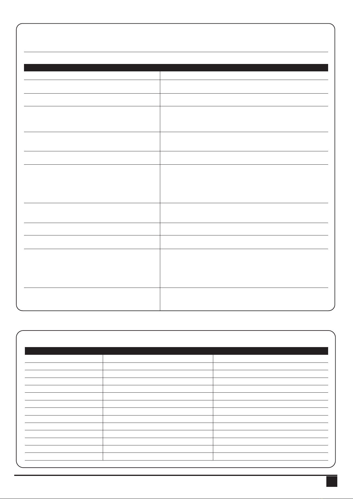
7.3 PR-2 Transmitter Data Sheet
Application
Frequency
Coding
Buttons
Power Supply
Operating Temperature
Dimension
Radio transmitter
433.92Mhz
Rolling code
4, for single-gate or dual-gate operation
3V with one CR2032 button type lithium battery
-20℃~+50℃
71.5mm * 33mm * 14mm
7.4 PF-1 Flashing Light Data Sheet
Application
Installation
Operating Temperature
Dimension
For outdoor use
Wall mounted vertically
-20℃~+50℃
85mm * 60.5mm * 40.5mm
Power Supply
Radio Frequency
Max. remote memorized
Dimensions
Output terminals
12V ~ 24V ac/dc
433.92Mhz
200pcs
106mm* 53mm* 20mm (L*W*H)
Output 1 & Output 2
7.5 PRB-1 External Receiver Box Data Sheet
7.2 PH-2 Photocell Data Sheet
Detection type
Operating distance
Response time
Input voltage
Operating Temperature
Protection class
Dimension
Through beam
25 meters
100ms
AC/DC 12~24V
-20℃~+60℃
IP54
96mm * 45mm * 43mm
12 INSTRUCTIONS PL600H/ PL1000H SLIDING GATE OPENER USER MANUAL
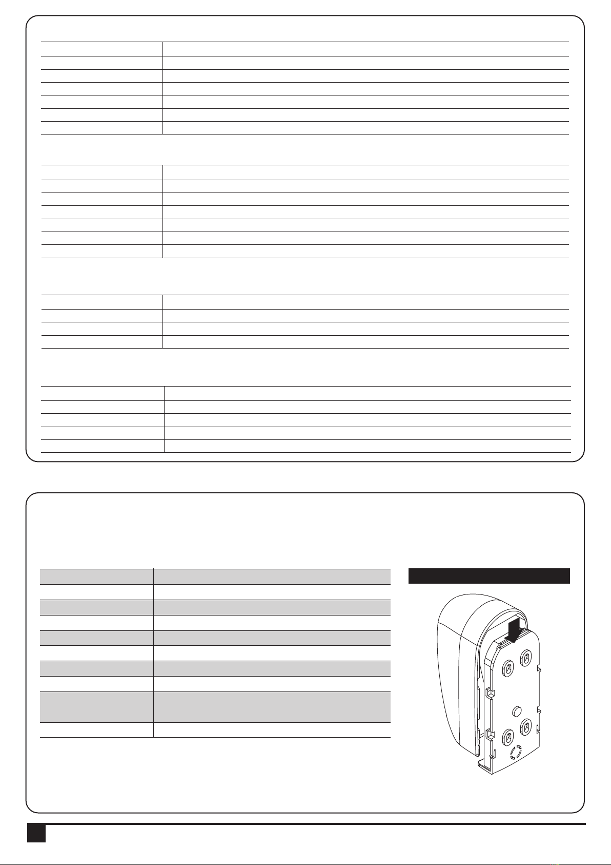
8.1. PHOTOCELL INSTALLATION GUIDE
The safety photocells are security devices for control automatic gates. Consist of one transmitter and one receiver based in
waterproof covers; it is triggered while breaking the path of the beams.
INSTALLATION:
Wire Connection of PH-2 Photocells See figure 4(2)
TX: Connect terminals 1 and 2 on the transmitter with the terminals Ph+ and GND on the P600B PCB.
RX: Connect terminals 1, 2 and 4 on the receiver with the terminals Ph+, GND and Ph1 on the P600B PCB.
And use an extra wire to connect terminals 2 and 5 on the receiver as a bridge.
Detection Method
Sensing Range
Input Voltage
Response Time
Emitting Element
Operation Indicator
Dimensions
Output Method
Current Consumption Max
Water Proof
Through Beam
25M
AC/DC 12~24V
100MS
IR LED
Red LED(RX): ON(When Beam is Broken), Green(TX):ON
96*45*43mm
Relay Output
TX: 35MA/Rx: 38MA (When beam aligned properly);
TX: 35MA/ Rx: 20MA (When beam is broken)
IP54
SPECIFICATION:
Figure 4(1)
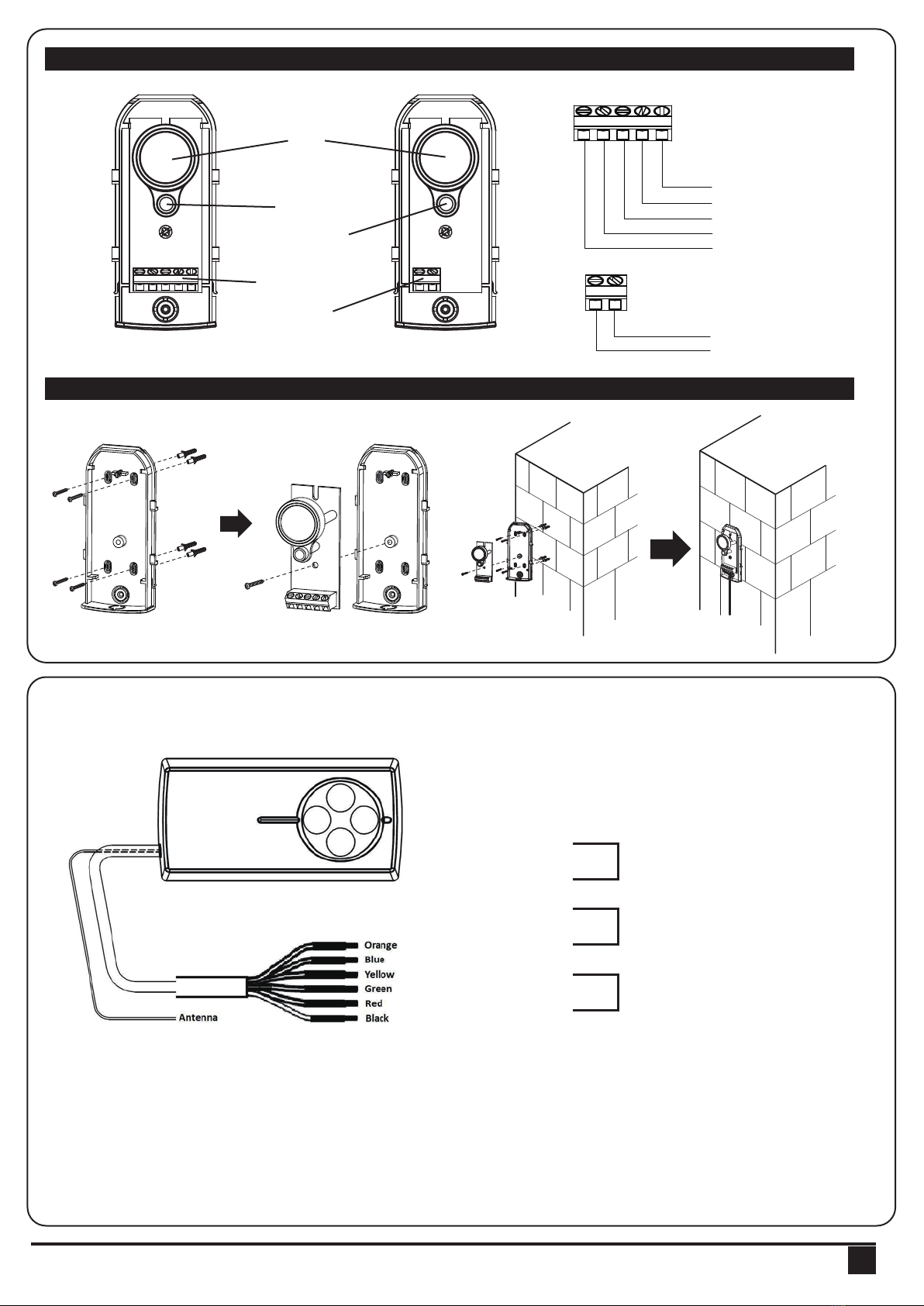
Situation:
In order to use one 4 channel remote to operate with additional device besides the original gate automation system. Install a
receiver box to connect with the 2nd device (such as another Powertech Slider)
or the 3rd device (Such as garage automation system)
Original gate automation: Using Button A & B (Pedestrian Mode) on the remote to control gate opener
2nd device: Install an external receiver box, connect output 1 to the 2nd device (such as another Slider, shown as below) use
button C on the same remote to control the 2nd device
3rd device: install an external receiver box, connect the output 2 to the 3rd device (such as garage door), use the Button D
now to operate.
8.2 Wire Connection and Setting of PRB-1 External Reciever Box
Orange
Blue
Yellow
Green
Red
Black
-Signal 1
-GND
-Signal 2
-GND
-12V/24V
-GND
Output 1 (Normally Open Relay)
Output 2 (Normally Open Relay)
12V - 24V AC/DC
RB1 Receiver Box
INSTRUCTIONS PL600H/ PL1000H SLIDING GATE OPENER USER MANUAL 13
RX
RX
Lens
Beam Alignmnet
Indicator
Power Led
Indicator
Terminal Block
Power
Terminal Block
COM
N.C.
N.O.
GND
DC (12~24V)
GND
DC (12~24V)
TX
TX
Figure 4(3)
Figure 4(2)
1 2 3 4 5
1 2 3 4 5 1 2
1 2
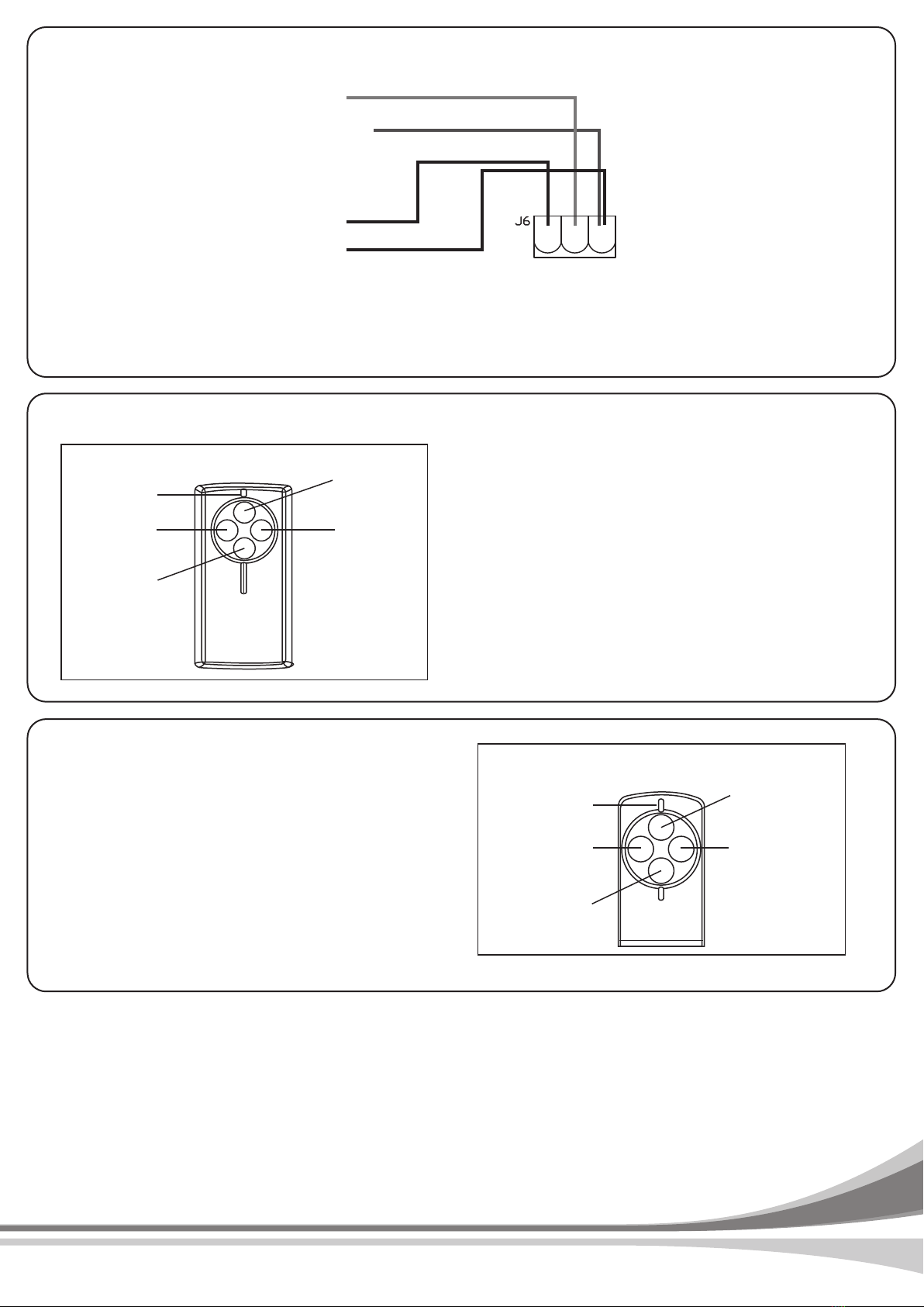
a. After connect all necessary cables properly , press
Test Button to exam if the output 1 is working, the
gate opener should operate.
b. If Output 1 is functional, press and hold Learn Button
for 1 second, the LED light should be “ON”
* If the LED does not respond, please check the
cable connection again
c. Press and hold Button C on the remote for 1 second
after the LED is “ON”. The remote completed the
memorizing process when LED light turns “OFF”
Device Testing & Remote Memorization
a. Orange cable (Signal 1) connect to terminal 10 (Pb) on the control board
b. Blue cable (GND) connect to terminal 11 (GND) on the control board
c. Red cable (12V/24V ac/dc) connect to terminal 9 (Ph+) on the control board
d. Black cable (GND) connect to terminal 11 (GND) on the control board
Press and hold learn button on the receiver box
for 10 seconds.
PRB-1 Receiver
PR-2
Orange
Blue
Yellow
Green
Red
Black
-Signal 1
-GND
-Signal 2
-GND
-12V/24V
-GND
9 10 11
GND
Pb
Ph+
Output 1 operation
LED Light Output 2 operation
Single-gate
operation
for Powertech
gate openers
Dual-gate
operation
for Powertech
gate openers
Memory Erasing
Please refer to figure 8.3.1
8.3 Channel Transmitter Operation
Figure 8.3.1
AB
C
D
LED Light
Learn Button Test Button
Output 1
Invalid Button
Invalid Button
34100-095-XXXX
Wire Connection:
This manual suits for next models
1
Table of contents
Other Timotion Gate Opener manuals


Popular Gate Opener manuals by other brands


Chamberlain
Chamberlain ELITE CSL24V installation manual

DKS
DKS 9100 Installation & owner's manual

Beninca
Beninca LADY-BE.I Operating instructions and spare parts catalogue

Chamberlain
Chamberlain CSW200UL8 owner's manual

Centsys
Centsys D5-Evo user guide

SEA
SEA Libra Mini Tank INSTALLATION MANUALS AND SAFETY INFORMATION