TINNO E205 User manual

1
Service Manual

2
Introduction
The purpose of this document is to help service workshop technicians to service products. This service
manual must be used only by authorized service suppliers. The content of it is confidential. Please note
that provides other guidance documents for service suppliers. Follow these regularly and comply with the
given instructions. While every effort has been made to ensure the accuracy of this document, some errors
may exist. Please keep in mind also that this documentation is continuously being updated and modified,
so always watch out for the newest version.
CAUTIONS
1、Please read this service manual carefully and make sure all elements of anti-static are in place before
the repair work is carried out.
2、Servicing and alignment MUST be undertaken by qualified personnel only.
3、Please use specified tools and equipments for servicing, in which the parameters need to be calibrated
with specified criteria.
Content
Chapter 1 Product Specification...................................................................................................................................................3
Chapter 2 Explosive View............................................................................................................................................................4
Chapter 3 Tools.............................................................................................................................................................................5
Chapter 4 Guidance of Disassembly/Assembly ...........................................................................................................................6
Chapter 5 Pictures of PCBA.......................................................................................................................................................10
Chapter 6 System block diagram................................................................................................................................................12
Chapter 7 Circuit diagram for each unit.....................................................................................................................................13
Chapter 8 Troubleshooting Guide...............................................................................................................................................19
Chapter 9 Firmware Upgrading Guide.......................................................................................................................................26
Chapter 10 CIT Testing ..............................................................................................................................................................34

3
Chapter 1 Product Specification
Specification:
Network: GSM/GPRS 900/1800 or 850/1900MHz
Display: 2.4“TFT QVGA
Blue tooth:Support: V1.2, Don’t Support: Stereo Music (for both SIMs)
Radio:FM radio FM Record to T-Flash
Talking time:567Min*
Standby time:260H*
Lithium Battery: Standard(1000mAh)
USB Charging:USB 2.0
*The actual time shall vary depending on the network situation
Main features and functions
Dual SIM Dual Standby Single Connection
FM Radio
Blue tooth (talk, file transfer)
Multi-Media
Camera:0.3M
USB 2.0 data transfer
T-Flash(Support 8G T Card)
2.4“TFT QVGA
MP3/3GP/MP4/AVI
82g(Handset weight:59g)

4
Chapter 2 Explosive View
AShell Lens
Keypad
LCD
DOME
Receiver
PCBA
Vibrator
Speaker
Camera
B Shell Antenna
Battery
Cover
5
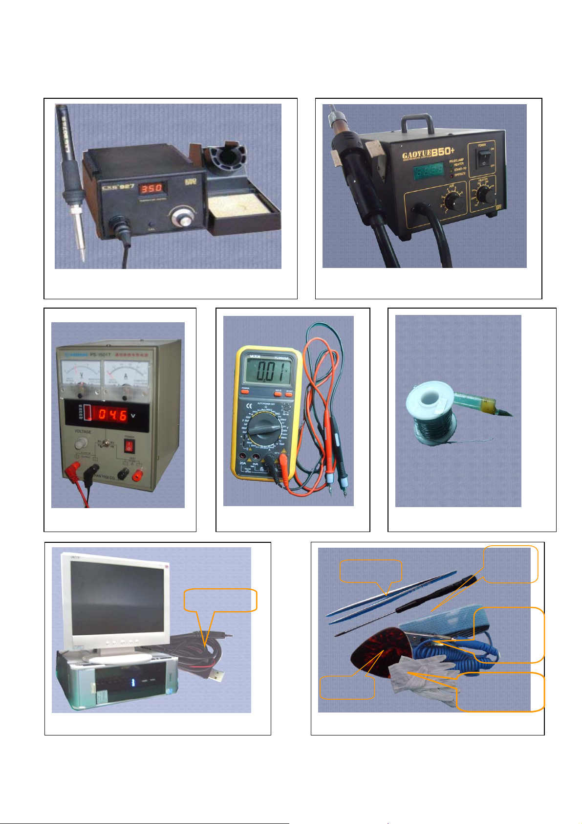
Chapter 3 Tools
Voltage Regulator(Figure 3)
Multi-meter(Figure 4)
Electric Iron(Figure 1)
Hot Air Gun(Figure 2)
Solder wire, soldering paste(Figure5)
PC, Data Cable(Downloading)(Figure 6)
Others(Figure 7)
Pick
Screw
Drive
r
Tweezers
Wrist
grounding
strap
Antistatic
gloves
DL Cable

6
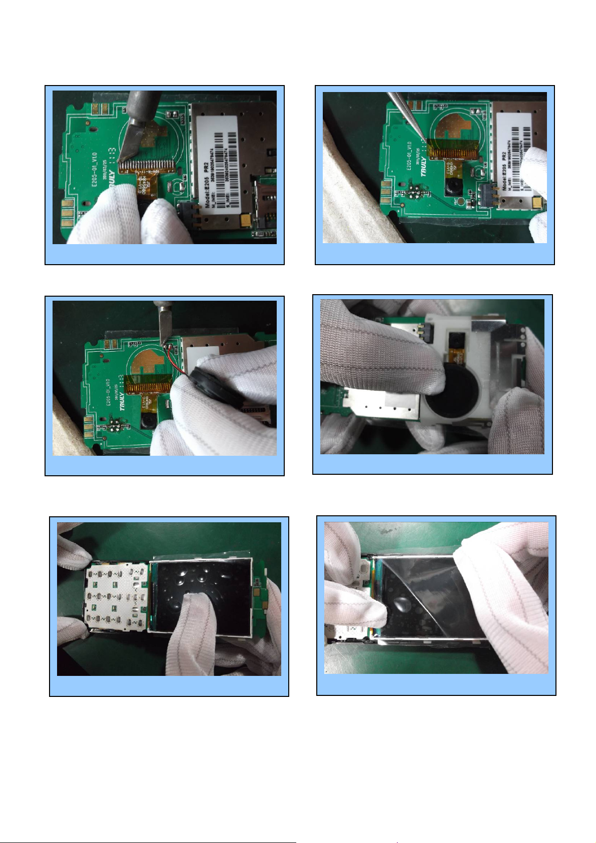
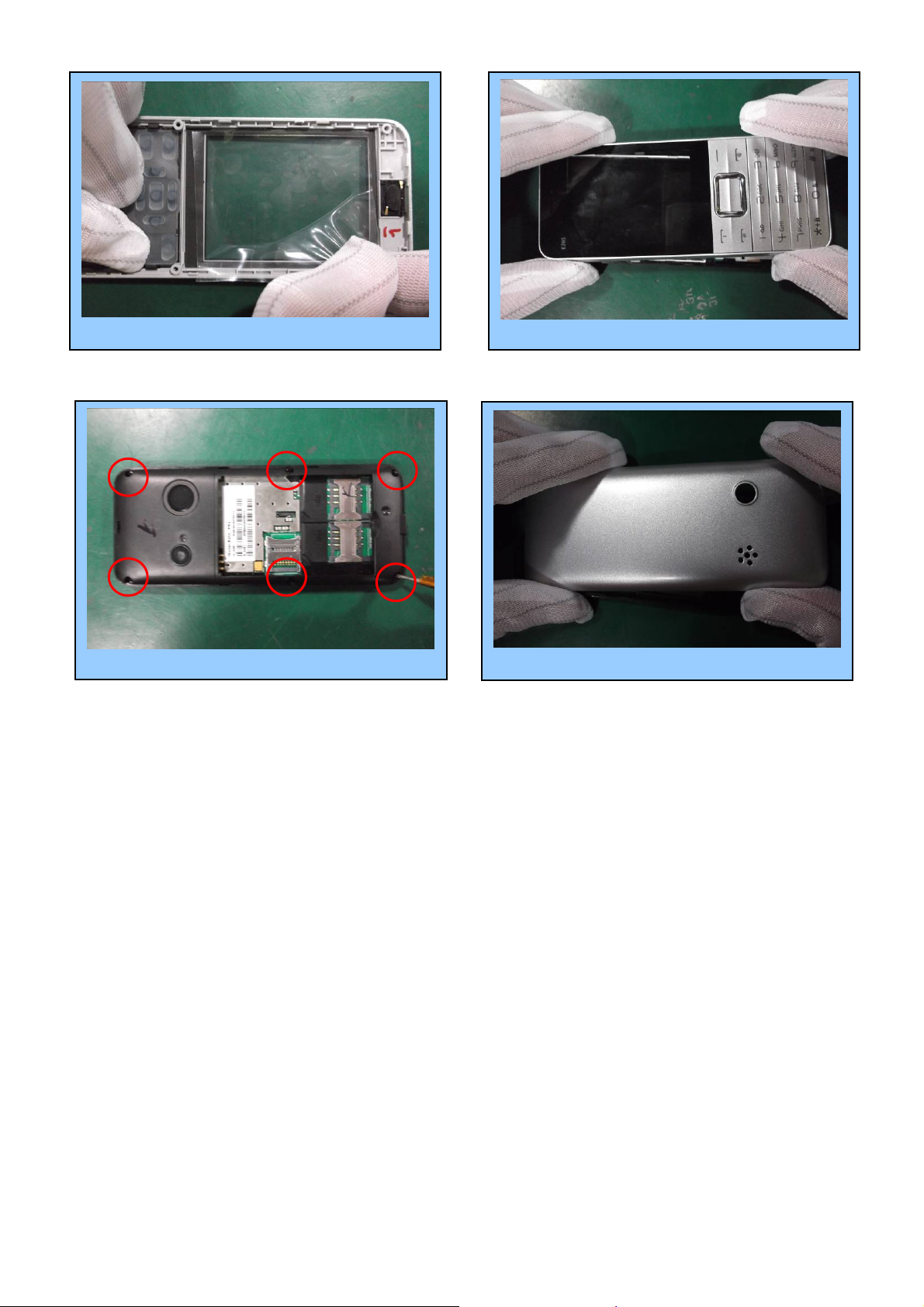
Chapter 4 Guidance of Disassembly/Assembly
4.1 Disassembly
Unscrewthesixscrews. 2
Removethefrontcover. 4
Stick the protection film onto LCD. 5
Remove the back cover by using pick. 3
Stick protection film onto lens. 6
Removethebatterycover. 1

7
Disassembly completed.
Take out PCBA (using Tweesers) . 7 Unmount LCD module. 8
Remove the LCD (Using Electric Iron). 9 Remove the speaker (Using Electric Iron). 10
Remove the camera(Using Electric Iron). 12
RemovetheESDfilm. 11
8
4.2 Assembly
Remove LCD protection film. 6
Mount the PCBA onto back cover. 5
Installtheantenna. 4
PastetheESDfilm. 2Solderthecamera. 1
SoldertheSpeaker. 3
9
Assembly completed.
Mountthefrontcover. 8Removetheprotectionfilm. 7
Tightenthescrews. 9 Installthebatterycover. 10
10
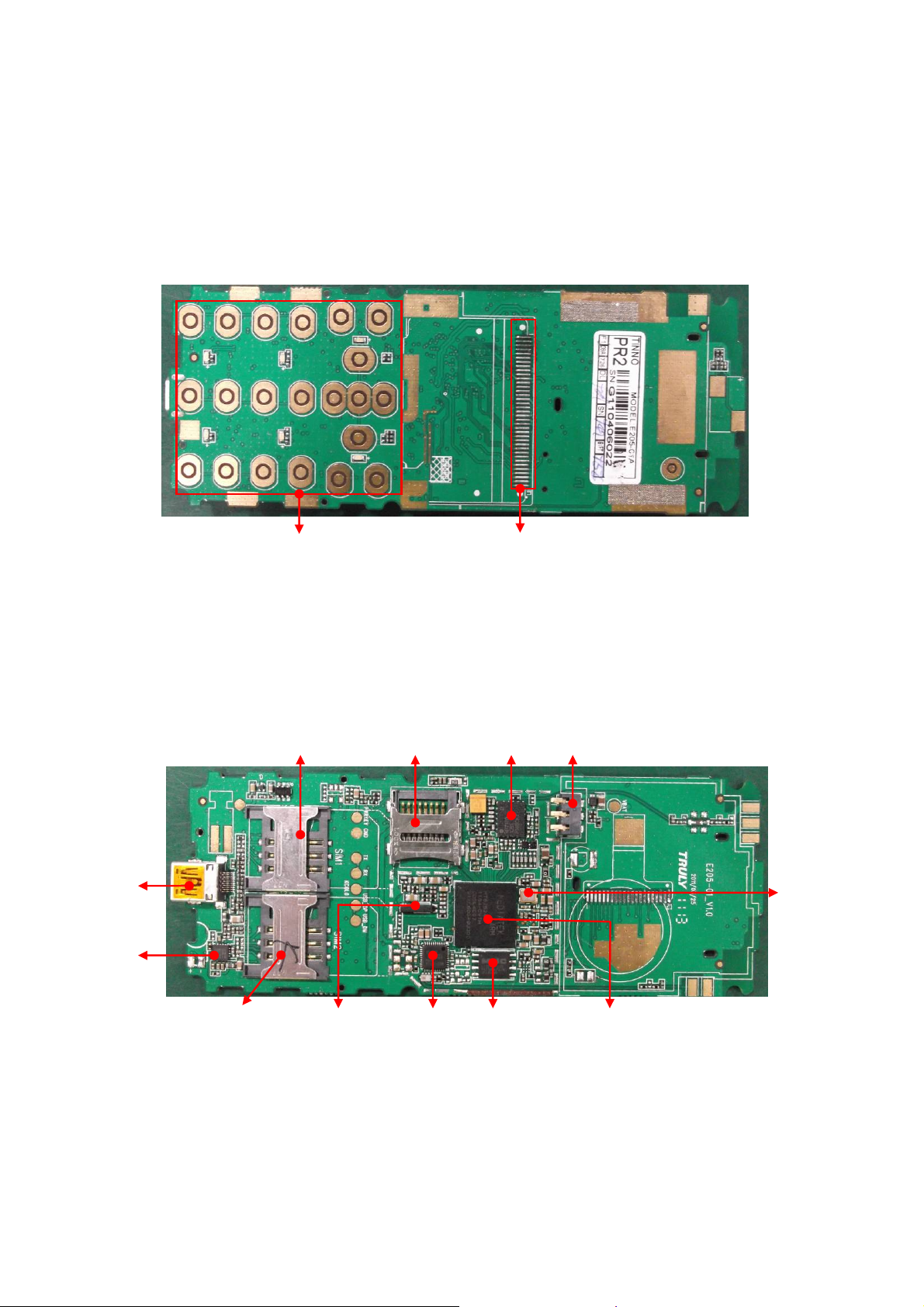
Chapter 5 Pictures of PCBA
5.1 Pictures
5.1.1 Instruction & location of main components on side A.
5.1.2 Instruction & location of main components on side B.
1
U101 CPU
MT6252
U502 PA
RF7170
Keypad input interface.
U301
Storage
J302
I\O Port
U402RF
Chipset AR1216
J201 battery
connector
U203 26M
Crystal
U705 BT
MT6612
X201
Crystal
J503 SIM
Jack
J502 SIM
Jack
Display interface
J301
TFLASH
Jack

11
5.2 Layout
5.2.1 Layout of side A
5.2.2 Layout of side B
12
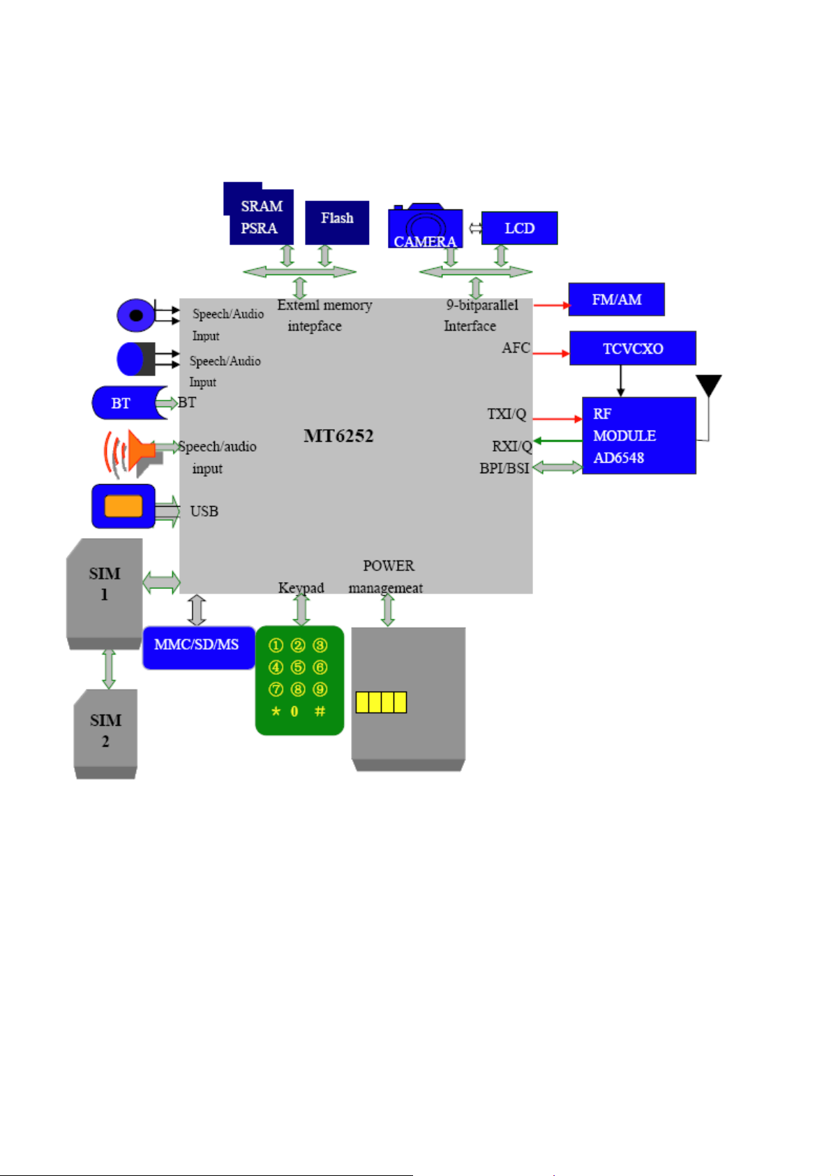
Chapter 6 System block diagram
13
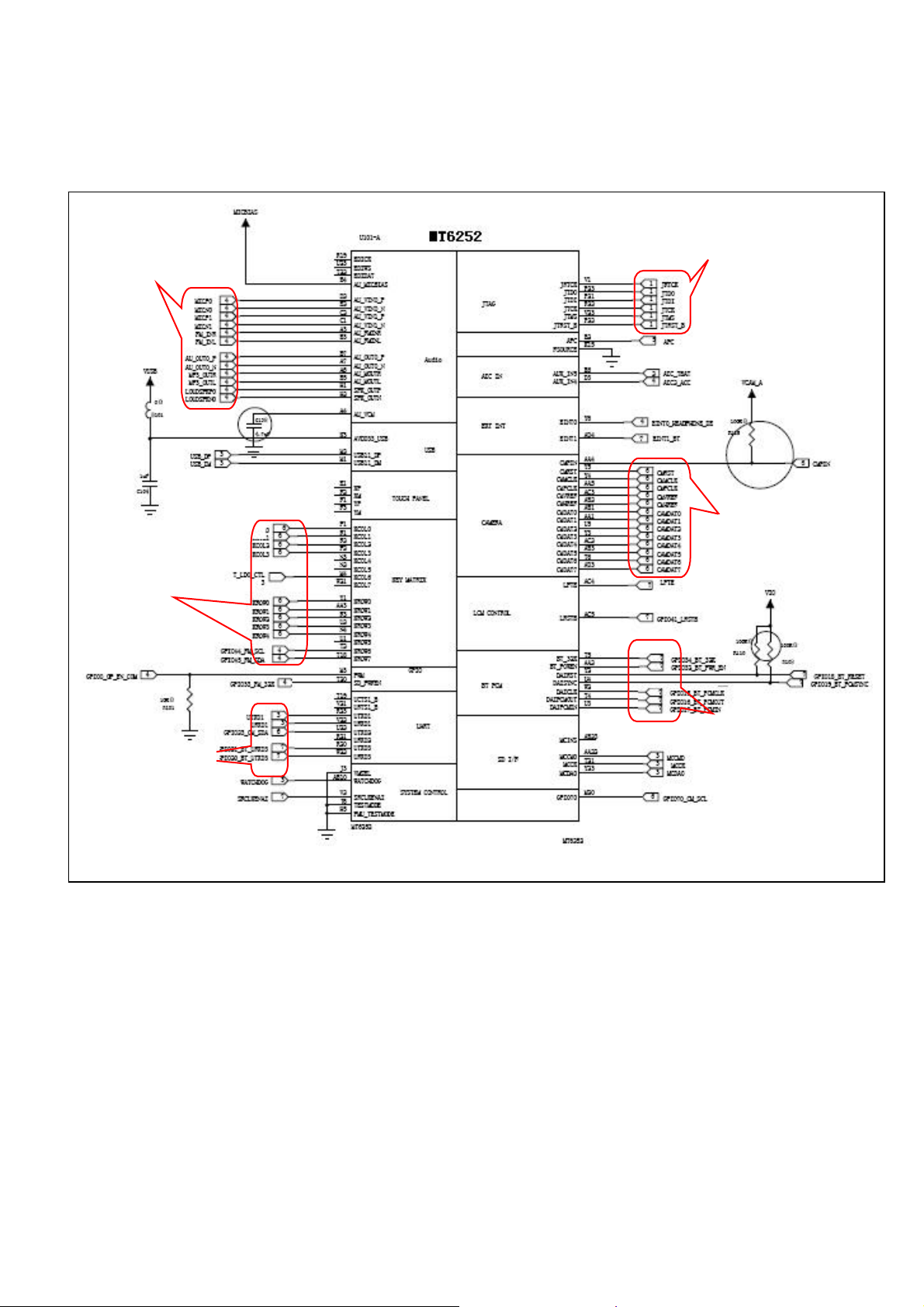
Chapter 7 Circuit diagram for each unit
7.1 CPU & Baseband
Audio processing
Keypad interface
数据传输接
口电
路
JAVA
Control
CAMERA
数据传输控
制端
BT
数据传输控
制端
Data transferring
control
Data transferring
control
Data transferring
interface

14
7.2 Keypad input interface
7.3 32.768 KHz clock crystal circuit
Clock Signal I/O
32.768 KHz
clock crystal
15
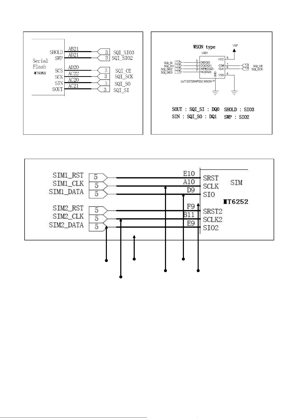
7.4 Data line of CPU and Flash
7.5 Output of SIM
SIM 2 Clock
SIM 2 Reset
SIM 2 Data SIM 1 Clock
SIM 1 Reset SIM 1 Data

16
7.6 Power output of MT6252 (CPU)
7.7 Battery connector
item voltage current
Vcore 1.2v 200ma
Vio 2.8v 100ma
Vadd 2.8v 150ma
Vtcxo 2.8v 20ma
Vrtc 1.2v 200ma
Vmem 2.8v 150ma
Vsim 2.8v 20ma
Vcs 2.8v 200ma
vcs 1.8v 150ma
Charging
Temperature Detector
电池正极
电压输入
Positive Voltage
Supply

17
7.8 Bluetooth
7.9 Audio Amplifier U201
Brief Introduction of Bluetooth: Bluetooth technology, a short distance wireless communication
technology, can simplify the communication between palmtop computers, notebook computers and
mobile phones, can also simplify the communication between these equipments and the Internet. The
data transfer between modern communication equipments and the Internet can be faster and more
efficient and the application of the wireless communication is accelerated. The Bluetooth technology
realize the wireless data and sound transfer from one point to several points, the transfer bound is a 10
meters radius sphere to the one point, the transfer bandwidth is 1Mbps, and the communication medium
is electroma
g
netic waves from 2.402GHz to 2.480GHz.
Audio Signal
Output
3.7V Power
Supply
Audio Start Signal
Audio Signal
Input
Antenna
Power Supply
Input of BT’s clock reset
Data
Transfer
Receiving/
Transmitting
of BT

18
7.10 I/O Interface
7.11 PowerAmplifier
Frequency
Band Selection
Power Supply
RF Signal Input
Receive Signal Output
Antenna
RF7170
Data
Transfer
Firmware
Downloadin
g
Charging
Volta
g
e In
p
ut
19
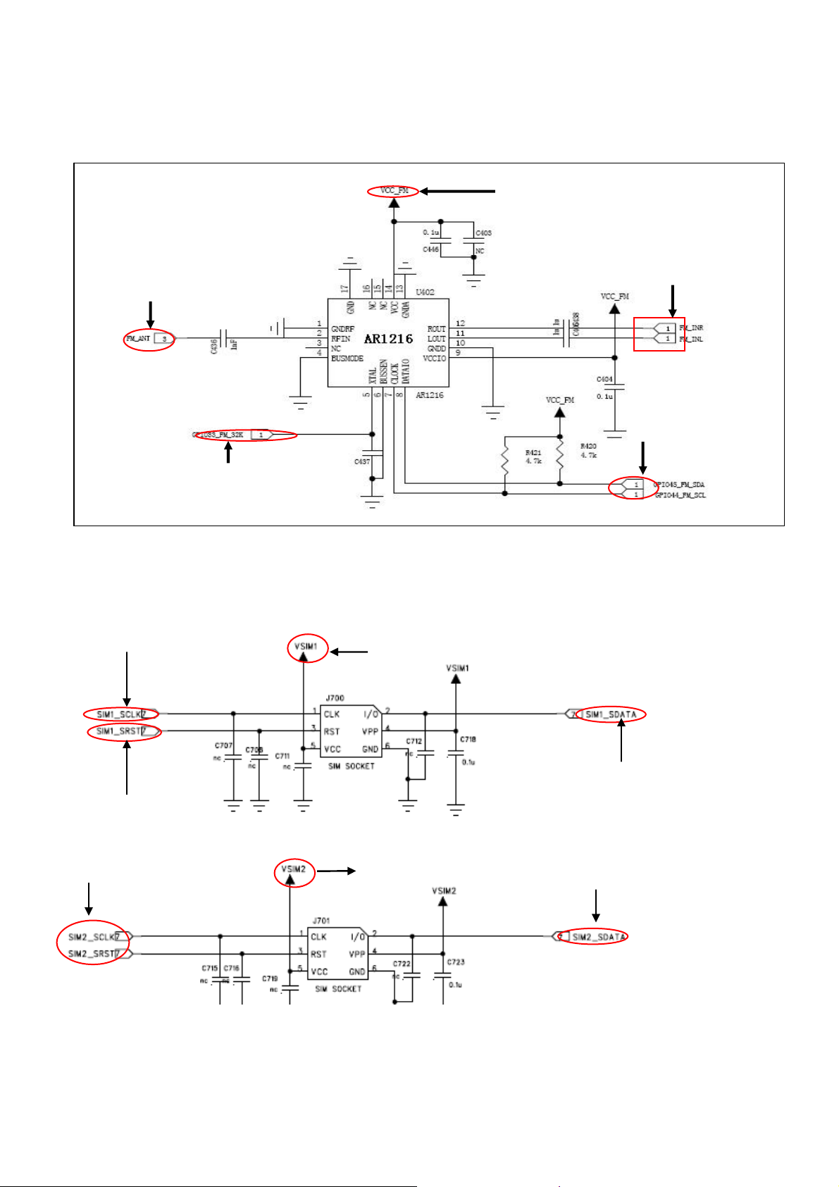
7.12 FM Radio Modules
The AR1216 processes the FM broadcasting signal that received from antenna (FM/ANT) ,produces and sends
audio signals (FM-INL, FM-INMR) to the audio process module of CPU for decoding, where the electrical signals of
audio are made.
7.13 SIM Circuit
Chapter 8 Troubleshooting Guide
SIM 1 Clock
SIM 1 Reset
SIM 1 Power Supply
SIM 1 Data
SIM 2 Power Supply
SIM 2 Clock, Reset SIM 2 Data
32K Clock signal input
Antenna
Audio output
Data Communication Port
2.7V Power Supply

20
Chapter 8 Troubleshooting Guide
8.1 Cannot Download Firmware
NO
Replace or
Re-solder I/O
connecto
r
Check if CPU has power
output and open circuit.
Cannot download
Check software
configuration, cable,
power supply, software,
C
Can power
On?
NO
NO
NO
NO
YES
YES
YES
YES
YES OK
Change or reconfigure
Check if I/O connector
is false weld or
dama
g
ed.
Plug the cable and check if
the current is high(normally
30mA).
Unplug the cable and check if
the chipset is overheated.
Check VCORE、VDD、VADD、
VTCXO、VRTC、VMEM、test
26MHZ、32KHZ Clock signal
Replace U101
Table of contents
Other TINNO Cell Phone manuals


