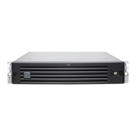
Tipping Point 50 Installation and operating manual

TippingPoint IPS Hardware
Installation and Safety Guide
V 2.5.4

Part Number: TECHD-0000000073
Publication Control Number: 070108:1500
Copyright © 2008 TippingPoint Technologies, Inc.. All rights reserved. This document contains
confidential information, trade secrets or both, which are the property of TippingPoint Technologies,
Inc. or one of its subsidiaries. No part of this documentation may be reproduced in any form or by any
means or used to make any derivative work (such as translation, transformation, or adaptation)
without written permission from TippingPoint Technologies, Inc. or one of its subsidiaties.
TippingPoint Technologies, Inc. reserves the right to revise this documentation and to make changes in
content from time to time without obligation on the part of TippingPoint Technologies, Inc. to provide
notification of such revision or change.
TippingPoint Technologies, Inc. provides this documentation without warranty, term, or condition of
any kind, either implied or expressed, including, but not limited to, the implied warranties, terms, or
conditions of merchantability, satisfactory quality, and fitness for a particular purpose. TippingPoint
Technologies, Inc. may make improvements or changes in the product(s) and/or the program(s)
described in this documentation at any time.If there is any software on removable media described in
this documentation, it is furnished under a license agreement included with the product as a separate
document.
UNITED STATES GOVERNMENT LEGENDS:
If you are a United States government agency, then this documentation and the software described
herein are provided to you subject to the following:
United States Government Legend: All technical data and computer software is commercial in nature
and developed solely at private expense. Software is delivered as Commercial Computer Software as
defined in DFARS 252.227-7014 (June 1995) or as a commercial item as defined in FAR 2.101(a) and as
such is provided with only such rights as are provided in 3Com’s standard commercial license for the
Software. Technical data is provided with limited rights only as provided in DFAR 252.227-7015 (Nov
1995) or FAR 52.227-14 (June 1987), whichever is applicable. You agree not to remove or deface any
portion of any legend provided on any licensed program or documentation contained in, or delivered
to you in conjunction with guide.
Unless otherwise indicated, TippingPoint Technologies, Inc. registered trademarks are registered in the
United States and may or may not be registered in other countries.
Digital Vaccine is a registered trademark. TippingPoint and the TippingPoint logo are trademarks of
TippingPoint Technologies, Inc. or one of its subsidiaries.
Microsoft and Windows are registered trademarks or trademarks of Microsoft Corporation in the
United States and/or other countries.
Other brand and product names may be registered trademarks or trademarks of their respective
holders.

TippingPoint IPS Hardware Installation and Safety Guideii i
Table of Contents
List of Figures vii
List of Tables ix
About This Guide xi
Overview xi
Target Audience xi
Organization xii
Conventions xiii
Headings xiii
Typeface xiii
Cross References xiii
Messages xiii
Warning xiv
Caution xiv
Note xiv
Tip xv
Related Documentation xv
Customer Support xvi
Chapter 1 Overview 1
Overview 1
TippingPoint Overview 1
Core Functionality 2
TippingPoint Environment 2
Threat Suppression Engine 3
IPS Devices 3
Local Security Manager 4
Security Management System 5
Threat Management Center 5

Table of Contents
ii TippingPoint IPS Hardware Installation and Safety Guide
Chapter 2 Prepare the Site 7
Overview 7
Safety Requirements 8
Rack and Clearance Requirements 12
Ventilation and Location 12
Environmental Requirements 12
Reliable Earthing 12
System Grounding Requirements 13
Grounding 13
Unpack the TippingPoint System 13
Chapter 3 TippingPoint 50 Overview 15
Overview 15
Chassis Overview 15
Chassis Features 16
LEDs 16
Power Switch 17
Liquid Crystal Display (LCD) 18
USB ThumbDrive 18
Model Requirements 18
Power Requirements 18
Cabling Requirements 18
Technical Specifications 19
Hardware Specifications 19
Technical Specifications 20
Software Specifications 20
Hardware Installation and Configuration 21
TNHA Hardware Configuration 21
TippingPoint 50 Chassis 22
Determine Total Rack Space 22
Bolt the Device to the Rack 22
Insert ThumbDrive 22
Connect the Power Supply 23
Attach Network Connections 23
Check LEDs 23
Setup Wizard 25

Table of Contents
TippingPoint IPS Hardware Installation and Safety Guide iii
Chapter 4 TippingPoint 100E Overview 27
Overview 27
Chassis Overview 28
Chassis Features 28
Technical Specifications 30
Hardware Specifications 30
Technical Specifications 31
Software Specifications 32
Hardware Installation and Configuration 32
TNHA Hardware Configuration 32
Install the TippingPoint Chassis 33
Determine Total Rack Space 33
Bolt the Device to the Rack 33
Connect the Power Supply 34
Attach Network Connections 34
Check LEDs 34
Setup Wizard 36
Chapter 5 TippingPoint 200E Overview 37
Overview 37
Chassis Overview 38
Chassis Features 38
Technical Specifications 39
Hardware Specifications 39
Technical Specifications 40
Software Specifications 41
Hardware Installation and Configuration 41
Install the Chassis 41
Determine Total Rack Space 42
Bolt the Device to the Rack 42
Connect the Power Supply 42
Attach Network Connections 43
Check LEDs 43
Setup Wizard 44
Chapter 6 TippingPoint 210E Overview 45
Overview 45
Chassis Overview 46
Chassis Features 46
Technical Specifications 47
Hardware Specifications 47
Technical Specifications 48
Software Specifications 49

Table of Contents
iv TippingPoint IPS Hardware Installation and Safety Guide
Hardware Installation and Configuration 49
Install the Chassis 49
Determine Total Rack Space 50
Bolt the Device to the Rack 50
Connect the Power Supply 50
Attach Network Connections 51
Setup Wizard 51
Chapter 7 TippingPoint 200/400/1200/2400
Overview 53
Overview 53
Chassis Overview 53
Chassis Features 54
Model Requirements 57
Power Requirements 57
Cabling Requirements 57
Fiber-Optic Connection Guidelines 58
Technical Specifications 58
Hardware Specifications 58
Technical Specifications 59
Software Specifications 60
Hardware Installation and Configuration 60
TippingPoint 200/400/1200/2400 Chassis 61
Determine Total Rack Space 61
Bolt the Device to the Rack 61
Connect the Dual Power Supply 62
Attach Network Connections 64
Check LEDs 64
Setup Wizard 66
Chapter 8 TippingPoint 600E/1200E/2400E/5000E
Overview 67
Overview 67
Chassis Overview 68
Chassis Features 69
Technical Specifications 71
Hardware Specifications 71
Technical Specifications 72
Software Specifications 73
Hardware Installation and Configuration 73
TNHA Hardware Configuration 74
Install the TippingPoint Chassis 74
Determine Total Rack Space 74

Table of Contents
TippingPoint IPS Hardware Installation and Safety Guide v
Bolt the Device to the Rack 75
Connect the Dual Power Supply 75
Attach Network Connections 77
Check LEDs 78
Setup Wizard 79
Appendix A: Connector and
Pinout Specifications 81
Management Processor Connectors 81
DB-9 (COM) Connector 81
DB-9 Connector Pinout 82
RJ-45 Connector 82
Port Connectors 83
Small Form-Factor Pluggable Transceivers 83
Appendix B: IPS Menu Options 85
IPS LCD Panel 86
Timeout 87
LCD Menu Overview 87
Backlight Set 87
Contrast Set 88
Halt OS 88
HA Query State 89
Layer 2 Fallback/Recover System 89
View Memory Usage 90
Serial # Query 90
Reload OS 90
IPS Messages 91
Appendix C: Power Supply
Module Replacement 93
Supported Platforms 93
Replacement Procedures for 300W Power Supply 94
Replacement Procedures for 400W Power Supply 95
Index 97

Table of Contents
vi TippingPoint IPS Hardware Installation and Safety Guide

TippingPoint IPS Hardware Installation and Safety Guide vii
List of Figures
Figure 3 - 1: TippingPoint Model 50 - Front Panel 16
Figure 3 - 2: TippingPoint Model 50 - Back Panel 16
Figure 4 - 1: TippingPoint Model 100E - Front Panel 28
Figure 4 - 2: TippingPoint Model 100E - Back Panel 28
Figure 6 - 1: TippingPoint 210E - Front Panel 46
Figure 6 - 2: TippingPoint 210E - Back Panel 46
Figure 7 - 1: TippingPoint Model 1200 - Front Panel 54
Figure 7 - 2: TippingPoint Model 1200 - Rear Panel 54
Figure 7 - 3: Protection for Power Supply Failure 62
Figure 7 - 4: Protection for Power Supply Failure and One Power Feed Circuit 63
Figure 7 - 5: Protection for Power Supply Failure and Both Power Feed Circuits 63
Figure 7 - 6: Maximum Protection for Power Supply Failure and Both Power Feed Circuits 63
Figure 8 - 1: TippingPoint Model 5000E - Front Panel 68
Figure 8 - 2: Protection for Power Supply Failure 76
Figure 8 - 3: Protection for Power Supply Failure and One Power Feed Circuit 76
Figure 8 - 4: Protection for Power Supply Failure and Both Power Feed Circuits 76
Figure 8 - 5: Maximum Protection for Power Supply Failure and Both Power Feed Circuits 77
Figure A - 1: DB-9 Connector 81
Figure A - 2: RJ-45 Connector 82
Figure A - 3: RJ-45 Connector 83
Figure A - 4: SFP Transceiver 84
Figure B - 1: Device Keypad 86

viii TippingPoint IPS Hardware Installation and Safety Guide

TippingPoint IPS Hardware Installation and Safety Guide ix
List of Tables
Table About - 1: TippingPoint Documents xv
Table About - 2: Customer Support Information xvi
Table 2 - 1: TippingPoint Environmental Requirements for the TippingPoint 12
Table 3 - 1: Segment Port LED Descriptions 17
Table 3 - 2: Management Port LED Descriptions 17
Table 3 - 3: TippingPoint-50 Specifications 19
Table 3 - 4: Model 50 Hardware Specifications 20
Table 3 - 5: Software Specifications for the TippingPoint-50 20
Table 3 - 6: Rack Space Requirements 22
Table 3 - 7: LED Descriptions for the IPS 24
Table 4 - 1: Segment Port LED Descriptions 29
Table 4 - 2: Management Port LED Descriptions 29
Table 4 - 3: TippingPoint 100E Specifications 30
Table 4 - 4: Model 100E Hardware Specifications 31
Table 4 - 5: Software Specifications for the TippingPoint 100E 32
Table 4 - 6: Rack Space Requirements 33
Table 4 - 7: LED Descriptions for the IPS 35
Table 5 - 1: Segment Port LED Descriptions 38
Table 5 - 2: TippingPoint 200E Specifications 39
Table 5 - 3: Model 200E Hardware Specifications 40
Table 5 - 4: Software Specifications for the TippingPoint 200E 41
Table 5 - 5: Rack Space Requirements 42
Table 5 - 6: Segment Port LED Descriptions 43
Table 6 - 1: Segment Port LED Descriptions 46
Table 6 - 2: Management Port LED Descriptions 47
Table 6 - 3: TippingPoint 210E Specifications 47
Table 6 - 4: TippingPoint 210E Hardware Specifications 48
Table 6 - 5: Software Specifications for the TippingPoint 210E 49
Table 6 - 6: Rack Space Requirements 50
Table 7 - 1: LED Descriptions 55
Table 7 - 2: Segment Port LED Descriptions 55
Table 7 - 3: Management Port LED Descriptions (Intel 845) 55
Table 7 - 4: Management Port LED Descriptions (Intel 865) 56
Table 7 - 5: Power Supply LED Descriptions 56
Table 7 - 6: Power Supply Audible Alarm Descriptions 57
Table 7 - 7: TippingPoint IPS Specifications 58
Table 7 - 8: Model 200/400/1200/2400 Hardware Specifications 59
Table 7 - 9: Software Specifications for the TippingPoint IPS 60
Table 7 - 10: Rack Space Requirements 61
Table 7 - 11: LED Descriptions for the IPS 65
Table 8 - 1: LED Descriptions 69
Table 8 - 2: Segment Port LED Descriptions 69
Table 8 - 3: Management Port LED Descriptions 70

x TippingPoint IPS Hardware Installation and Safety Guide
Table 8 - 4: Power Supply LED Descriptions 70
Table 8 - 5: Power Supply Audible Alarm Descriptions 70
Table 8 - 6: TippingPoint 600E/1200E/2400E/5000E IPS Specifications 71
Table 8 - 7: TippingPoint 600E/1200E/2400E/5000E Hardware Specifications 72
Table 8 - 8: Software Specifications for the TippingPoint IPS 73
Table 8 - 9: Rack Space Requirements 74
Table 8 - 10: LED Descriptions for the IPS 78
Table A - 1: DB-9 Connector Pinouts 82
Table A - 2: RJ-45 Connector Pinouts 82
Table A - 3: RJ-45 Connector Pinouts 83
Table A - 4: SFP Transceiver Information 84
Table B - 1: LCD Panel Buttons 86
Table B - 2: IPS Messages 91

IPS Hardware Installation and Configuration Guide xi
About This Guide
Explains who this book is intended for, how the information is organized, where information
updates can be found, and how to obtain customer support if you cannot resolve a problem.
Overview
Welcome to t he TippingPoint (TP) IPS Hardware Installation and Configuration Guide. The
UnityOne™ is an Intrusion Prevention System that provides a unified approach to network security.
The Local Security Manager (LSM) and Security Management System (SMS) provide management
options for your IPS devices and network security.
This chapter includes the following sections:
•“Target Audience” on page xi
•“Organization” on page xii
•“Conventions” on page xiii
•“Related Documentation” on page xv
•“Customer Support” on page xvi
Target Audience
This guide is intended for use by technicians and maintenance personnel responsible for installing,
configuring, and maintaining the UnityOne™. Users should be familiar with telecommunications
products and networking concepts.

xii TippingPoint IPS Hardware Installation and Safety Guide
Organization
The TippingPoint IPS Hardware Installation and Safety Guide is organized as follows:
About the Guide
Explains who this book is intended for, how the information is organized, where information updates
can be found, and how to obtain customer support if you cannot resolve a problem.
TippingPoint Overview
Provides a description of the deployment environment of the TippingPoint, including layout and
illustrations of hardware components and features.
Prepare the Site
Provides general requirements for the installation site and guidelines for electrical and network
connections. For specific requirements, review the chapter according to device model.
TippingPoint 50 Overview
Provides a description of the deployment environment of the TippingPoint-50, including layout and
illustrations of hardware components and features. The chapter includes specification and advanced
information for maintaining your TippingPoint device.
TippingPoint 100E Overview
Provides a description of the deployment environment of the TippingPoint 100E, including layout
and illustrations of hardware components and features. The chapter includes specification and
advanced information for maintaining your TippingPoint device.
TippingPoint 200E Overview
Provides a description of the deployment environment of the TippingPoint 200E, including layout
and illustrations of hardware components and features. The chapter includes specification and
advanced information for maintaining your TippingPoint device.
TippingPoint 210E Overview
Provides a description of the deployment environment of the TippingPoint 210E, including layout
and illustrations of hardware components and features. The chapter includes specification and
advanced information for maintaining your TippingPoint device.
TippingPoint 200/400/1200/2400 Overview
Provides a description of the deployment environment of the TippingPoint 200/400/1200/2400,
including layout and illustrations of hardware components and features. The chapter includes
specification and advanced information for maintaining your TippingPoint device.
TippingPoint 600E/1200E/2400E/5000E Overview
Provides a description of the deployment environment of the TippingPoint 1200E/2400E/5000E,
including layout and illustrations of hardware components and features. The chapter includes
specification and advanced information for maintaining your TippingPoint device.

TippingPoint IPS Hardware Installation and Safety Guide xiii
Appendix A: Connector and Pinout Specifications
Provides connector and pinout information for the UnityOne™ system.
Appendix B: IPS Menu Options
Provides detailed information on the LCD functions for models supporting this feature.
Conventions
This book, and the other books in this series, follow some conventions for structuring information.
Headings
Every chapter starts with a brief description of the information you can find in that chapter, which
correlates with the major headings in that chapter. Each major heading corresponds to a task or
concept that is important for you to understand. Headings are of a different size and type to make them
easy to skim, whether you are viewing an online or print copy of this document.
Typeface
This book uses the following typeface conventions:
Bold Used for the names of screen elements like buttons, drop-down lists, or fields. For
example, when you are done with a dialog, you would click the OK button.
Code Used for text a user must type to use the product.
Italic Used for book titles, variables, and important term.
Hyperlink Used for web site and cross reference links.
Cross References
When a topic is covered in depth elsewhere in this guide, or in another book in this series, a cross
reference to the other information will be provided. Cross references within this book will take the
form: “for more information about conventions, see page 6, Conventions.” Cross references to other
publications will take the form: “for more information about <topic>, see Publication Name.”
Messages
Messages are special text that are emphasized by font, format, and icons. There are four types of
messages in this book:
•Warning
•Caution
•Note
•Tip

xiv TippingPoint IPS Hardware Installation and Safety Guide
A description of each message type with an example message follows.
Warning
Warnings tell you how to avoid physical injury to people or equipment. For people, injury includes
anything from temporary conditions, such as pain, to irreversible conditions such as death. For
equipment, injury means anything requiring repair. Warnings tell you what you should or should not
do, and the consequences of not heeding the warning.
Warnings have an icon to the left showing a white lightning bolt drawn inside of a red octagon.
Warnings also start with the word “WARNING”, and are presented in bold face type.
Caution
Cautions tell you how to avoid a serious loss that stops short of physical damage such as the loss of data,
time, or security. Cautions tell you what you should or should not do to avoid such losses, and the
consequences of not heeding the caution.
Cautions have an icon to the left showing a black exclamation point drawn inside of a yellow triangle.
Cautions also start with the word “CAUTION”.
Note
Notes tell you about information that might not be obvious, or that does not relate directly to the
current topic, but that may affect relevant behavior.
A note has an icon to the left showing a piece of note paper, and starts with the word “Note”.
WARNING: Only trained and qualified personnel should install, replace, or
service this equipment. Disconnect the system before servicing.
CAUTION: Do not type del *.* from the root (C:\) directory. Typing del *.* from the root
directory will destroy all the program and configuration data that your computer needs to
run, and will render your system inoperable.
Note: Most car rental companies no longer allow cash deposits in lieu of a credit
card when renting a car. Non-credit card deposits can only be arranged by a
lengthy application and approval process.

TippingPoint IPS Hardware Installation and Safety Guide xv
Tip
Tips are suggestions about how you can perform a task more easily or more efficiently.
A tip has an icon to the left showing a light bulb drawn inside and starts with the word “Tip”.
Related Documentation
The UnityOne™ systems have a full set of documentation. These publications are available in
electronic format on your installation CDs. For the most recent updates, check the Threat
Management Center (TMC) web site at https://tmc.tippingpoint.com.
Tip: Setting the logging parameter to “off” or “minimal” will improve your
system’s processing performance, but it will make debugging very difficult in the
event of a system crash. During system integration, you can set logging to “full” to
ease debugging. After you have finished testing, set logging to “minimal” to
improve performance.
Table About - 1: TippingPoint Documents
Audience Publication Location
Hardware
Te c h n i c i a n s
•Quick Start TippingPoint 50
•Quick Start TippingPoint 50 Thumbdrive
•Quick Start TippingPoint 100E
•Quick Start TippingPoint100E Thumbdrive
•Quick Start TippingPoint 200 E
•Quick Start TippingPoint 210E
•Quick Start TippingPoint 1200E/2400E/5000E
•Quick Start TippingPoint 200/400/1200/2400
printed version in the UnityOne™
box, UnityOne™ Documentation CD,
https://tmc.tippingpoint.com
•TippingPoint IPS Hardware Installation and
Safety Guide
•TippingPoint Zero Power High Availability
Installation Guide
•TippingPoint Modular Fiber/Copper ZPHA
Installation Guide
UnityOne™ Documentation CD,
https://tmc.tippingpoint.com
TippingPoint SMS Installation and
Configuration Guide
printed version in the UnityOne™
box, UnityOne™ Documentation CD,
https://tmc.tippingpoint.com,
SMS server

xvi TippingPoint IPS Hardware Installation and Safety Guide
Customer Support
The TippingPoint Technologies customer support phone number is 1-866-681-8324.
TippingPoint Technologies is committed to providing quality customer support to all of its
customers. Each customer is provided with a customized support agreement that provides detailed
customer and support contact information. For the most efficient resolution of your problem, please
take a moment to gather some basic information from your records and from your system before
contacting customer support, including your customer number (on the Customer Support Agreement
and shipping invoice that came with your system).
System
Administrators
TippingPoint Local Security Manager User’s
Guide
UnityOne™ Documentation CD,
https://tmc.tippingpoint.com
TippingPoint Local Security Manager Online
Help
available in the LSM application
TippingPoint Command Line Interface Reference UnityOne™ Documentation CD,
https://tmc.tippingpoint.com
TippingPoint SMS Installation and
Configuration Guide
hard copy in the shipping materials,
UnityOne™ Documentation CD,
https://tmc.tippingpoint.com
TippingPoint Security Management System
User’s Guide
UnityOne™ Documentation CD,
https://tmc.tippingpoint.com
and on the SMS server
TippingPoint Security Management System
Online Help
available in the SMS application
TippingPoint SMS Web Services API UnityOne™ Documentation CD,
https://tmc.tippingpoint.com
and on the SMS server
Third Party Management for TippingPoint IPS UnityOne™ Documentation CD,
https://tmc.tippingpoint.com
Table About - 1: TippingPoint Documents (Continued)
Table About - 2: Customer Support Information
Information Location
Your customer number You can find this number on your Customer Support Agreement and on
the shipping invoice that came with your TippingPoint system.
Yo u r N D S s e r i a l n u m b e r You can find this number on the shipping invoice that came with
your UnityOne™ system.

TippingPoint IPS Hardware Installation and Safety Guide xvii
Yo u r N D S s o f t wa r e v e r s i o n
number
You can find this information in the LSM in the System Stats
frame, in the Update tab, or by using the CLI show version
command.
Your NDS system boot time You can find this information in the LSM in the System Stats
frame.
Table About - 2: Customer Support Information
Information Location

xviii TippingPoint IPS Hardware Installation and Safety Guide
This manual suits for next models
11
Table of contents
Popular Firewall manuals by other brands
Fortinet
Fortinet FortiGate 310B-LENC quick start guide
D-Link
D-Link DFL-210 - NetDefend - Security Appliance user manual
Draytek
Draytek VDSL2 quick start guide
ZyXEL Communications
ZyXEL Communications ZyXEL ZyWALL 5 quick start guide
Arxceo
Arxceo ALLY IP1000 user guide
IBM
IBM DataPower XH40 quick start guide
Allied Telesis
Allied Telesis AT-AR4050S-5G installation guide

Fortinet
Fortinet FortiGate 300C quick start guide
Brocade Communications Systems
Brocade Communications Systems 5600 vRouter reference guide

Symantec
Symantec 10268947 - Network Security 7160 user guide
SonicWALL
SonicWALL NSA 250M series Getting started guide

Lanner
Lanner FW-7571 user manual
