Tischer Trail 200 User manual
Operating instructions
Tischer Freizeitfahrzeuge
-TRAIL / BOX 200
-TRAIL / BOX 215 / 230
-TRAIL / BOX 240
-TRAIL / BOX 260 / 260 S/260 S
-TRAIL / BOX 260 R / 260 RS
-TRAIL / BOX 305 S
-TRAIL / BOX 280 / 280 S

2 of 90
1 Preface
Dear customer,
Welcome as new owner of a Tischer TRAIL camper ca in. We are excited to welcome you as one of
our customers.
Your camper ca in can offer you a particular road usage spectrum far eyond the limits of a
traditional camper ca in. The ca in with sound and state-of-the-art technology guaranties good
quality, highest sta ility and a long service life.
As a start, please carefully read the entire operating instructions.
For uild-in units (heater, cooking place, toilet, refrigerator, etc.), the respective operating manuals and
operating instructions are decisive.
Please o serve the information in the respective instructions in order to avoid unnecessary
malfunctions.
If you resale or loan the ca in, please provide these operating instructions and the uild-in units to the
new owner or renter.
We wish you many relaxing leisure and vacation days with your camper ca in and always a safe drive.
Your Tischer-Team
Imprint
Reprinting, reproduction or translation, in whole or in part, is not permissi le without the written
permission of Tischer Gm H Freizeitfahrzeuge. All statutory copyrights are explicitly reserved to
Tischer Gm H Freizeitfahrzeuge.
If modifications are made without written permission y Tischer Gm H Freizeitfahrzeuge, any warranty
or guarantee o ligations of the Tischer Gm H Freizeitfahrzeuge for damage and defects caused y
the unauthorized modification shall e voided.
Furthermore, Tischer Gm H Freizeitfahrzeuge shall not e lia le for damage su sequently caused y
the unauthorized modification.
Tischer GmbH Freizeitfahrzeuge Tel.: +49 (0) 9342 / 8159
Frankenstraße 3 Fax: +49 (0) 9342 / 5089
Industriegebiet Wiebelbach Internet: www.tischer-trail.de
Leisure vehicles operating instructions Edition 3/2011

3 of 90
Table of contents
1
Preface ................................................................................................................ 2
2
Safety information ............................................................................................. 6
2.1 Use of sym ols ........................................................................................................ 6
2.2 General safety information ...................................................................................... 6
2.3 Road safety ............................................................................................................. 6
2.4 Danger of fire .......................................................................................................... 6
2.5 In case of fire........................................................................................................... 6
3
Raising and lowering the cabin ........................................................................ 7
3.1 Lowering the ca in (200 to 260 RS and 305 S only) ................................................ 7
3.2 Power supply........................................................................................................... 8
3.3 Lowering the ca in (280 / 280 S only) ....................................................................11
3.4 Raising the ca in (200 to 260 RS and 305S only) ..................................................12
3.5 Raising the ca in (280 / 280 S only) .......................................................................16
3.6 Connecting electrical supports (special equipment) ................................................19
3.7 Picking up the ca in (200 to 260 RS and 305 S) ....................................................24
3.8 Picking up the ca in (280 / 280 S only) ..................................................................27
3.9 Lowering the ca in using electrical supports (special equipment)...........................29
3.10 Securing the ca in (200 to 260 RS and 305 S only) ...............................................35
3.11 Securing the ca in (280 / 280 S only) .....................................................................36
4
Battery............................................................................................................... 38
4.1 General safety information for attery handling ......................................................38
4.2 Battery (200 to 260 RS and 305 S only) .................................................................39
4.3 Battery (280 / 280 S only) .......................................................................................39
5
Living/Operation .............................................................................................. 40
5.1 Important information .............................................................................................40
5.2 Entry door ..............................................................................................................40
5.3 Door lind ...............................................................................................................42
5.4 Screen door ...........................................................................................................43
5.5 Step .......................................................................................................................44
5.6 Electrical step (special equipment) .........................................................................45
5.7 Heating/Ventilation 215 to 305S (special equipment for 200) .................................45
5.8 Heating/Ventilation (215 to 305 S with L equipment only) .......................................46
5.9 Gas cylinder compartment door..............................................................................47
5.10 Waste-holding tank door (215 to 305 S with L equipment only) ..............................49

4 of 90
5.11 Water tank (215 to 305 S with L equipment only) ...................................................50
5.12 Passage way door (280 S special equipment) ........................................................51
5.13 Side windows .........................................................................................................51
5.14 Com ination lind ..................................................................................................54
5.15 Curtains ..................................................................................................................56
5.16 Skylight ..................................................................................................................57
5.17 Panorama skylight (special equipment) ..................................................................59
6
Furniture ........................................................................................................... 62
6.1 Ta le (200 to 260 RS only) .....................................................................................62
6.2 Ta le (280 / 280 RS and 305 S only) .....................................................................64
6.3 Ca inets .................................................................................................................65
7
Electrical equipment ........................................................................................ 67
7.1 Lighting ..................................................................................................................67
7.2 Board control system PC100 (standard equipment, 200 not supported) .................69
7.3 Board control system PC200 (special equipment, 200 not supported) ....................69
7.4 Entrance light (special equipment) .........................................................................70
8
Awning (special equipment) ........................................................................... 71
8.1 Support struts .........................................................................................................72
8.2 Support struts (awnings only, which do not exceed the length of the ca in) ...........73
9
Kitchen .............................................................................................................. 74
9.1 Kitchen light ...........................................................................................................74
9.2 Ho cover ...............................................................................................................75
9.3 Extending the working area (special equipment) ....................................................75
9.4 Gas ho .................................................................................................................76
9.5 Refrigerator ............................................................................................................76
10
Sanitary installation ......................................................................................... 77
10.1 Fresh water supply (standard equipment) ..............................................................77
10.2 Fresh water supply (215 to 260 and 305 S with L equipment only) .........................77
10.3 Fresh water supply (280 /280 S with L equipment only) .........................................78
10.4 Waste water tank (215 to 260 RS and 305 S only) .................................................79
10.5 Waste water tank (280 / 280 S only) .......................................................................79
10.6 Cassette Porta Potti (215 to 280 S and 305 S with L equipment only) ....................81
10.7 Sink (215 to 305 S only) .........................................................................................82
10.8 Sink (280 / 280 S only) ...........................................................................................83
10.9 Shower ca in (280 / 280 RS and 305 S only) .........................................................84
10.10 Bathroom skylight ...............................................................................................85

5 of 90
11
Gas supply ........................................................................................................ 86
11.1 Gas test ..................................................................................................................88
12
Troubleshooting ............................................................................................... 89
12.1 Trou le shooting of the electrical supports .............................................................89
6 of 90
2 Safety information
2.1 Use of symbols
Caution
Type and source of danger
•
Refers to information, which must e complied with in order to
avoid any endangerment of persons.
Attention
Type and source of danger
•
Refers to information, which must e complied with in order to
avoid any damage to or destruction of material.
Note
•
Explaining description to the respective chapters.
2.2 General safety information
The oxygen in the ca in interior is consumed y reathing or operation of the gas cooker or other
uild-in units. For this reason, skylights with forced ventilation are installed.
Danger of suffocation due to increased car on dioxide content. Keep the forced ventilation
uno structed.
2.3 Road safety
Ensure that no persons are in the ca in while driving.
In front of underpasses, tunnels or similar, the overall vehicle height must e o served.
During winter time keep the ca in roof free from snow and ice prior to departure.
If accessories or special equipment is installed, vehicle dimensions, weight and handling may change.
2.4 anger of fire
Keep com usti le materials away from heating and cooking appliances.
Lamps may ecome hot. If the lamp is switched on, the safety distance to com usti le o jects must
always e 30 cm. Fire hazards exist!
2.5 In case of fire
Evacuate all vehicle passengers.
Switch off the electrical supply and pull off the mains plug.
Close the main cut-off valve on the gas cylinder.
Alert others and call the fire rigade.
Fight the fire if possi le without taking any risk.

7 of 90
3 Raising and lowering the cabin
3.1 Lowering the cabin (200 to 260 RS and 305 S only)
(The work steps are explained on the example of the right ca in side. Repeat the work steps
analogously for the left side).
Opening the flaps to the turnbuckles
Remove the seat cushion from the left seat ench and insert key 1 into lock cylinder 2 of the flap. Turn
key 1 clockwise.
Press oth lock cylinders 2 until the flap unlocks.
Caution
Risk of injuries
•
Secure the flap against closing.
Open flap 1. The turn uckles and the power supply of the vehicle are located under flap 1. The vehicle
power supply is only located on the right side of the ca in.

8 of 90
3.2 Power supply
isconnecting the power supply of the vehicle
Note
•
Please o serve the information in chapter Battery.
Turn the locking mechanism of 13-pin plug 1 counterclockwise and pull off plug 1.
Connecting an external power supply
Open the flap of power socket 1. In the direction of travel, power socket 1 can e found on the left side
on the outer wall.
.

9 of 90
Connecting the power supply cable
Press fastener 1 of your external power supply ca le 2. Insert the plug into the power socket.
10 of 90
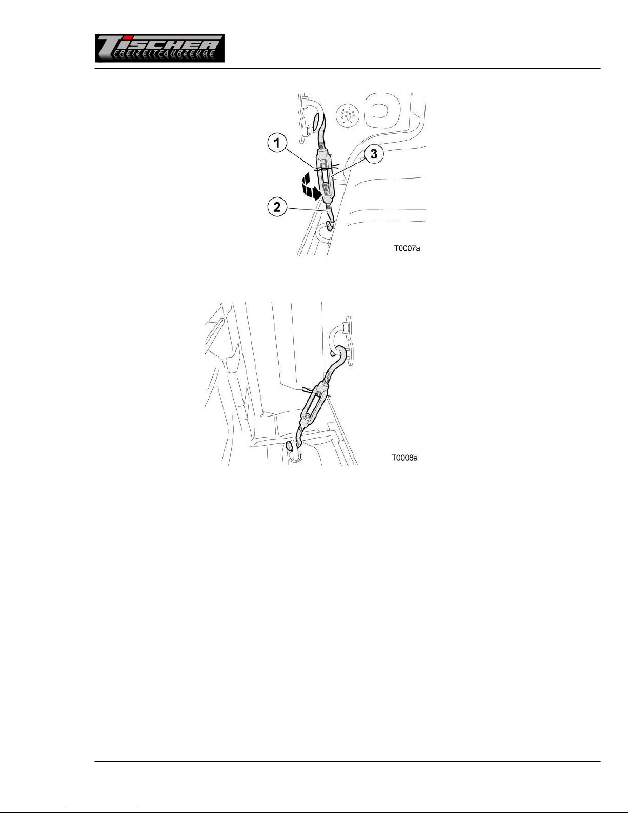
Loosening the cabin fastening (turnbuckles)
.
Pull cotter pin 1 from turn uckle 2.
Turn loop 3 until front turn uckle 2 can e disengaged.
Loosen the rear turn uckle. Close the flaps accessing the turn uckles.
The ca in is now detached from the vehicle and can e lifted.

11 of 90
3.3 Lowering the cabin (280 / 280 S only)
Loosening the cabin fastening
Use enclosed crank 1 to loosen and unscrew the fastening screws.
Completely unscrew fastening screws 1 with washers 2.
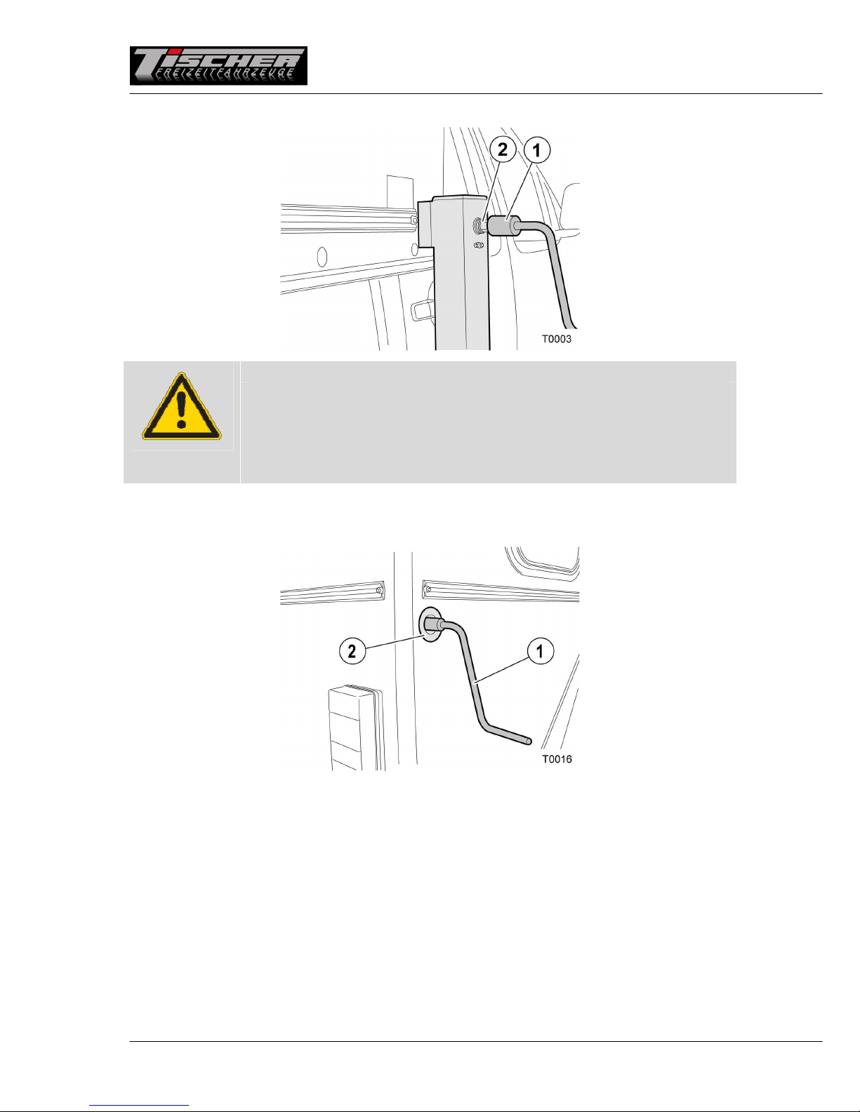
isconnecting the power supply
The plug connection is located on the left side of the vehicle.
Turn the locking mechanism of 13-pin plug 1 counterclockwise and pull the plug out of power socket 2.

12 of 90
3.4 Raising the cabin (200 to 260 RS and 305S only)
Mounting the front crank supports and electrical supports (special equipment)
Remove front support 1 from transport holder 3. Open tu e lynch pin 2.
Insert front support 1 into the adapter on the ca in.

13 of 90
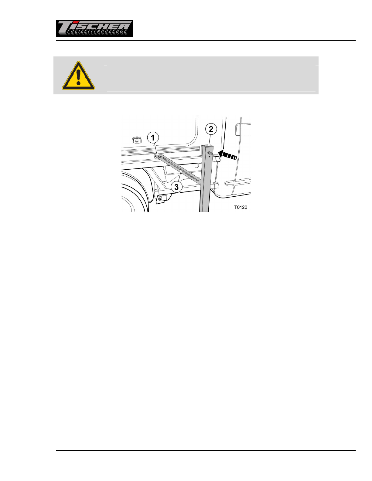
Mounting the support struts
Fold support strut 1 upwards.
Secure support strut 1 to threaded olt 2 on the inner side of the ca in outer wall y screwing wing nut
3 on tight.
Preparing the crank supports
Loosen cotter pin 1. Pull olt 2 out of attachment part 3. Secure attachment part 3 using one hand.
Pull attachment part 3 out of the support until the suita le hole and insert olt 2 through the support
and attachment part 3. Insert cotter pin 1 into olt 2.
Place one of pads 4 under every support.
14 of 90
Raising the cabin using the crank supports
Attention
Risk of damage
•
Make sure to never raise the rear of the ca in higher than the front.
This could result in the alcove resting on the roof of your carrier
vehicle.
• Start raising the ca in using the front supports.
Insert crank 1 into adapter 2 and turn the crank clockwise until the support touches the ground.
Raise the ca in y alternately extending all four supports y a few turns.
First extend the front supports followed y the rear supports.

15 of 90
Note
•
If the ca in is parked for an extensive period of time without the
carrier vehicle, it is recommended to retract the supports a it. The
ca in is more sta le on retracted supports.
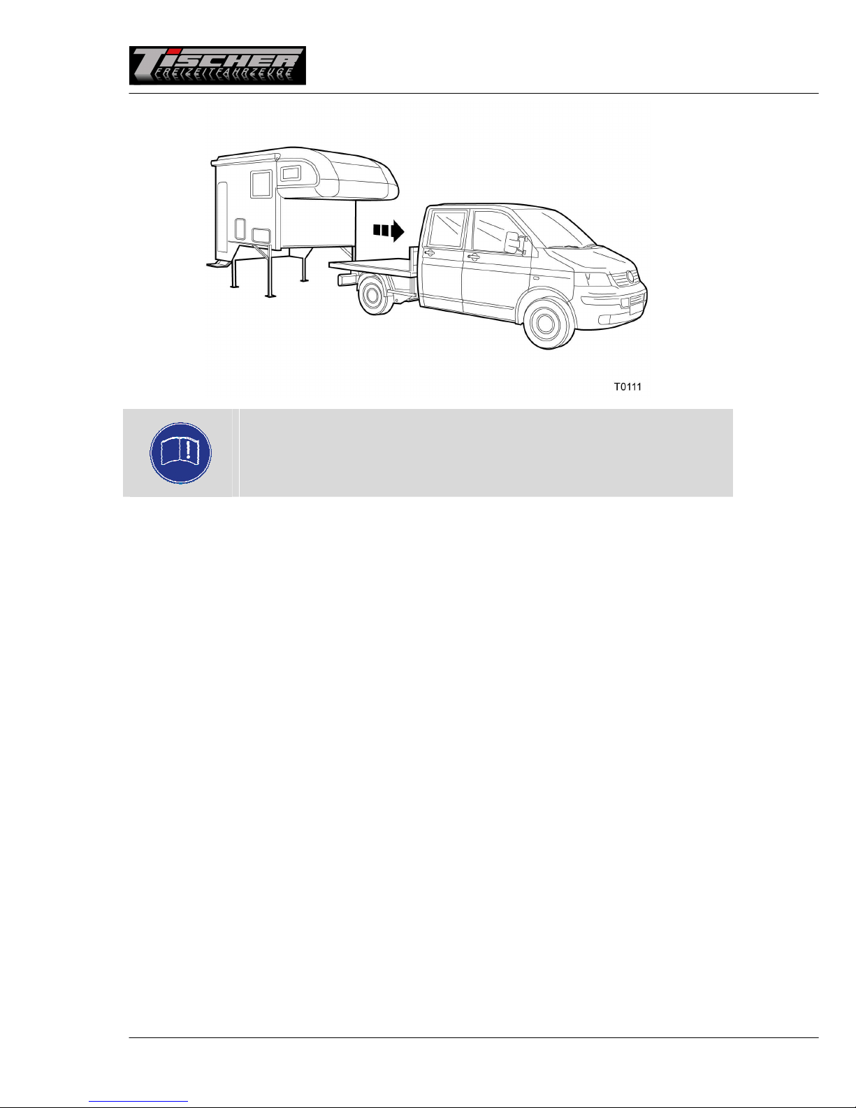
Completely raise the ca in y the means of all four supports. Now drive in a straight line out from
under the ca in.
16 of 90
3.5 Raising the cabin (280 / 280 S only)
Attention
Risk of damage
•
In case of vehicles with air suspension, the air suspension must e
completely lowered.
Mounting the front crank supports
Remove front crank support 2 from the stowage ox and insert it into the adapter on the ca in.
Fold support strut 3 up and secure it to the ca in using wing screw 1.

17 of 90
Raising the cabin using the crank supports
Attention
Risk of damage
•
Make sure to never raise the rear of the ca in higher than the front.
This could result in the alcove resting on the roof of your carrier
vehicle.
• Start raising the ca in using the front supports.
Insert crank 1 into adapter 2 and turn the crank clockwise until the support touches the ground.
Raise the ca in y alternately extending all four supports y a few turns.
18 of 90
Note
•
If the ca in is parked for an extensive period of time without the
carrier vehicle, it is recommended to retract the supports a it. The
ca in is more sta le on retracted supports.
Completely raise the ca in y the means of all four supports. Now drive in a straight line out from
under the ca in.

19 of 90
3.6 Connecting electrical supports (special equipment)
In case of electrical supports, connect the plugs of the front supports.
Preparing electrical supports (special equipment)
The rear supports are already assem led ready for use.
Loosen cotter pin 1. Pull olt 2 out of attachment part 3. Secure attachment part 3 using one hand.
Pull attachment part 3 out of the support until the suita le hole and insert olt 2 through the support
and attachment part 3. Insert cotter pin 1 into olt 2.
Place one of pads 4 under every support.
20 of 90
Raising the cabin using electrical supports (special equipment)
Attention
Risk of damage
•
Make sure to never raise the rear of the ca in higher than the front.
This could result in the alcove resting on the roof of your carrier
vehicle.
• Start raising the ca in using the front supports.
• Use the option to extend all supports at the same time.
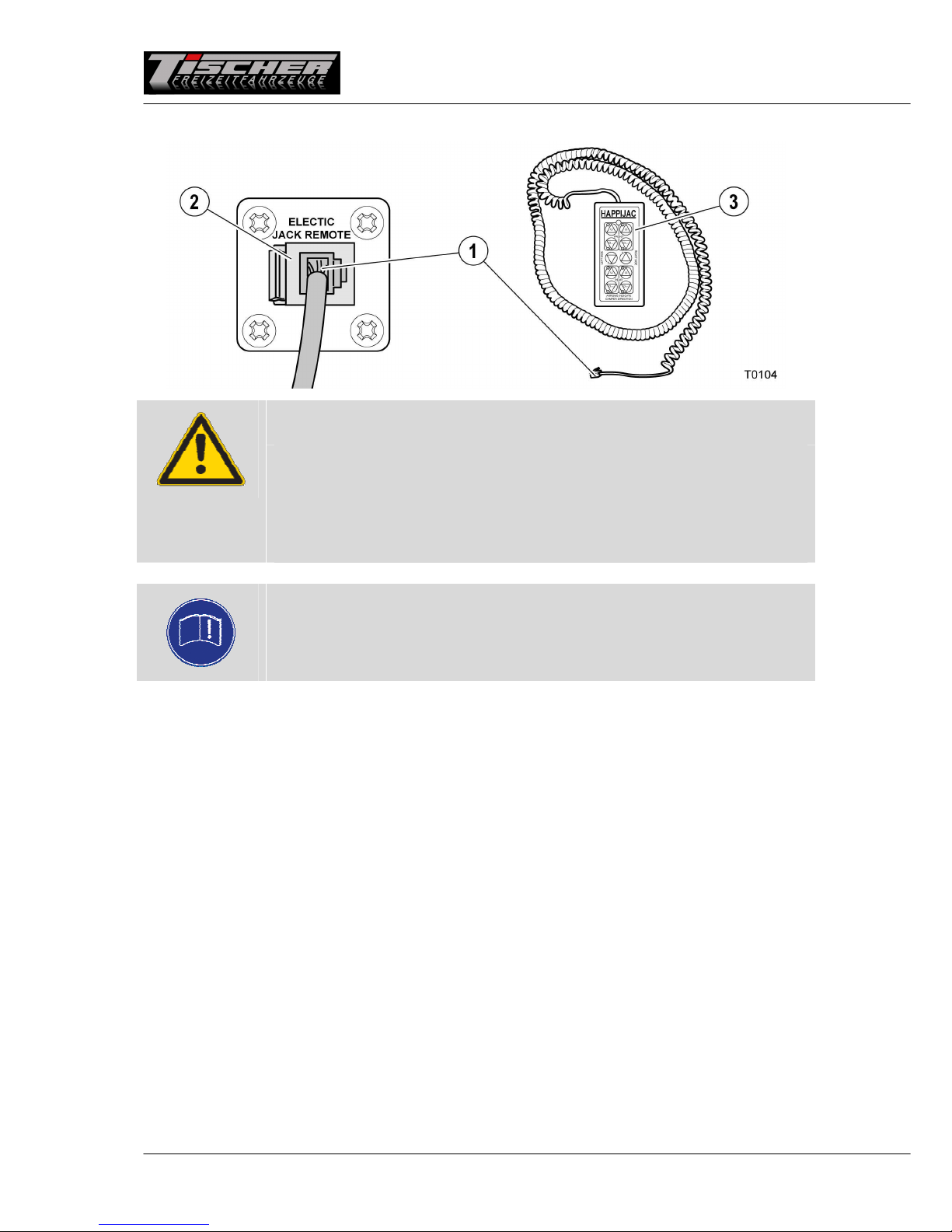
Note
•
It is optionally possi le to operate the electrical supports using a
wireless remote control.
In case of ca ins with electrical supports, insert plug 1 of remote control 3 into ushing 2 in the interior
next to the entry door. Position yourself such that you have a clear view of the ca in. The length of
remote control ca le 3 is sufficient to walk around the ca in.
This manual suits for next models
22
Table of contents


