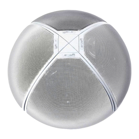
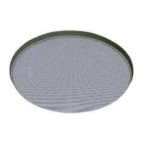
TKA SP-C61T User manual

SP-C61T
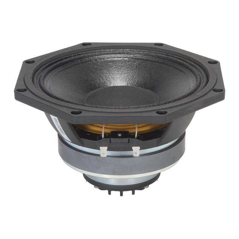
6.5”High Resolution Speaker
Installation Manual
安装手册

2
Table of Contents 目录
Introduction...........................................................................................................3
Speaker Back Panel................................................................................................4
Wiring Info –70V Operation ..................................................................................5
Speaker Wire...................................................................................................................... 5
Adjust the Tap Settings..................................................................................................... 7
Wiring Info –8 Ohm Operation..............................................................................8
Speaker Wire...................................................................................................................... 8
Tap Setting Knob...............................................................................................................9
Prewiring............................................................................................................................9
Impedance Matching for Amplifiers and Speakers.......................................................... 9
Installation...........................................................................................................10
Specification ........................................................................................................11
Warranty .............................................................................................................12
引言.....................................................................................................................13
扬声器背板..........................................................................................................14
线缆连接 –70V 工作模式................................................................................15
音箱线 ............................................................................................................................... 15
调整变压器设置旋钮 .......................................................................................................... 17
线缆连接 –8 欧姆工作模式 ..............................................................................18
音箱线 ............................................................................................................................... 18
变压器设置旋钮 ................................................................................................................. 19
布线................................................................................................................................... 19
功率放大器和扬声器的阻抗匹配......................................................................................... 19
安装.....................................................................................................................20
技术指标 .............................................................................................................21
产品保修 .............................................................................................................22

3
Introduction
Thank you for selecting the Taska Contractor Series in-ceiling speakers. These
high-resolution speakers have combined acoustic technology with durability and will
provide years of musical enjoyment. The speaker line provides solutions for
conference sound reinforcement, background music, dedicated music listening and
home theater for audio system using either fixed impedance or 70V amplification.With
an easily adjustable tap setting switch on the back of the speaker, these versatile
speakers even include a bypass setting to allow their use as high performance 8-ohm
speakers.
The Taska Contractor Series combines premium acoustic materials, with our most
advanced drivers to deliver exceptional performance in every application. From
commercial conference audio to spectacular surround sound, Taska Contractor
speakers offer the finest sound around.
Taska Contractor Series speakers feature high quality drivers, sophisticated
crossover networks, and advanced designs to ensure optimum reproduction in
different application, no matter what the source material may be.

4
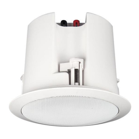
Speaker Back Panel
Tap Setting Knob
For easy adjustment of the tap settings
With options for :
3.75W, 7.5W, 15W, 30W (70V)
8ΩBypass
MULTI TAPPING

5
Wiring Info –70V Operation
Speaker Wire
Wiring speakers for 70V systems is simple and easy. A single run of 2-conductor,
stranded wire is run to every speaker location leaving a small loop (60~90 cm is
usually more than sufficient depending on the speakers and their mounting type) at
each speaker location. You can place additional loops for future expansion or for
making speaker location changes if needed.
Note: This is very different from typical low-impedance wiring used for traditional
audio installations where a dedicated run of wire goes from each speaker back to the
amplifier. 70V wiring uses much less wire and the wire used can be a much higher
gauge (thinner wire) even though it is used in a longer run.
Here is a chart showing some of the differences possible among wire lengths for both
low impedance (4Ω-8Ω) and high impedance (70V) systems:
Speaker Cable Length for Various Gauges at Low and High Impedance
AWG
Power Loss in Cable (% Loss & dB Loss)
4 Ohm Speakers
8 Ohm Speakers
70V Speakers
11%
21%
50%
11%
21%
50%
11%
21%
50%
0.5 dB
1 dB
3 dB
0.5 dB
1 dB
3 dB
0.5 dB
1 dB
3 dB
6
84m
174m
588m
169m
348m
1.2km
4.14km
8.5km
29km
8
53m
109m
370m
106m
219m
740m
2.6km
5.5km
18.1km
10
33.5m
69m
233m
67m
138m
466m
1.6km
3.4km
11.4km
12
21m
43m
146m
42m
87m
292m
1km
2.1km
7.2km
14
13m
27m
92m
27m
55m
184m
648m
1.3km
4.5km
16
8m
17m
56m
16m
38m
113m
398m
819m
2.8km
18
5m
11m
36m
10m
21m
71m
251m
516m
1.75km
20
3m
7m
23m
6m
13m
45m
158m
331m
1.1km
22
2m
4m
14m
4m
8m
28m
98m
201m
681m
24
1m
3m
9m
2m
5m
17m
62m
127m
429m
Note: Unlike traditional stereo audio, 70V systems are typically run in mono sound so
that only a single two conductor wire run is necessary for the speakers. If you want to
use multiple wire runs for zoning speakers or other purposes, each 2-conductor wire
needs to be independently run back to its own amplifier or amplifier terminals if using
a multi-channel amplifier.
1. At each speaker location, cut the loop of wire at the speaker location.
2. Strip 1 to 2 inches (2.5 to 5 cm) off the end of the cable jacket. Then strip ½-inch
(1.3 cm) of insulation off each wire.
3. Twist the wire strands together so there are no strands separated from the bundle.

6
4. Connect the wires to the speaker terminals, being sure to observe proper polarity.
For standard speaker cable with red and black wires, connect both red wires (the
red wire coming from the 70V connection on the amplifier or the previous speaker
if there was one AND the red wire going to the next speaker if there is an
additional speaker) to the red positive (+) terminal and both black wires (the black
wire coming from the COM connection of the 70V amplifier or the previous
speaker if there was one AND the black wire going to the next speaker if there is
an additional speaker) to the black negative (–) terminal.
Note: Some speaker cables may have other ways of designating polarity. Cable with a
clear jacket has a copper-colored wire for positive and a silver-colored wire for
negative. In a cable with white and black wires, the white is positive (70V) and the
black is negative (COM). Cable with both wires the same color may have grooves,
ribs, or stripes on the positive wire to identify it.
5. Check to make sure there are no stray strands of wire outside the terminals. If
there are, remove the wire, twist the strands together, and reconnect the wire to
the terminal.
6. At the final loudspeaker, the only wires connected will be the ones coming from
the previous loudspeaker (or from the amplifier if there is only one speaker in the
system).

7
Adjust the Tap Settings
The SP-C61T speakers have the following tap settings available:
70V: 3.75W, 7.5W, 15W, 30W
8Ω (bypasses the internal transformer)
The tap settings will affect the overall volume of the loudspeaker in the system. When
designing a 70V system, care must be taken not to exceed the power rating of the
amplifier or dangerous clipping may occur. Clipping is the most common cause of
damage to loudspeakers and should be avoided at all times.
The standard rule is to design a system that leaves 20% of the amplifier’s rated power
as a reserve. For example, with a 300-watt amplifier, speakers should never be set
with taps that total higher than 240-watts. The amplifiers total load is determined by
adding the wattage of each speaker. When thicker wire or exceptionally long wire runs
are used, there is an additional component of current loss due to the cable that can
become significant and must be considered in the calculation. For our example with a
300-watt amplifier, here are the approximate number of speakers that could be used if
each speaker used the following tap settings:
Example: 300-Watt Amplifier (saving 20% for overhead, means 240 usable watts maximum)
Tap Settings and maximum number of speakers (depending on wire gauge and length)
3.75W : Max of 56-64 speakers
7.5W : Max of 28-32 speakers
15W : Max of 14-16 speakers
30W : Max of 7-8 speakers
For a 70V system, most installations are designed to blanket an area using more
loudspeakers at a lower tap setting rather than using fewer speakers at a higher tap
setting. This is done to avoid hot spots where very loud sound is heard in certain
areas and less in others. It is much more common for 70V speakers to be set at their
lowest tap setting than at their highest, but each installation may require adjustments
due to the application or environment.
You can adjust the tap setting at any time by turning the tap setting knob to the new
position, but make sure not to exceed the amplifier’s total available wattage when
doing so.

8
Wiring Info –8 Ohm Operation
Speaker Wire
The amount of wire needed varies with speaker placement. Label speaker wires
with left/right or specific cable ID and room location.
What kind to use: We recommend using reputable brand of 16 to 12 gauge
multi-stranded wiring for amplifier-to-speaker connections.
Selecting the proper gauge: Wire is measured in gauges: the bigger the number,
the smaller the wire. The gauge of wire needed is determined by the distance between
your amplifier and the speakers. The longer the run, the heavier the gauge needed.
Use the following chart as a guide:
Length Minimum Gauge
0 ~ 30m 16
15 ~ 45m 14
30 ~ 60m 12
If the conductors are not sheathed in colored jackets, be consistent with usage.
The standard colors on the terminals are red Positive (+) and black Negative (-). If the
wire has transparent insulation, one conductor will be copper-colored (+) and the
other silver-colored (-). If the wire has an opaque insulation, the conductors are
differentiated by a series of ribs or grooves, a stripe, or dotted line on one conductor.
Use and mark these as the Positive (+) conductor.
Typical usage of speaker wire conductors

9
Tap Setting Knob
When using the SP-C61T speakers with a low impedance system
(such as with a 4Ω or 8Ω amplifier), make sure that the tap setting
switch is set to the 8Ω position. This is the only appropriate setting
when using the SP-C61T speakers with a low impedance
amplifier.
Prewiring
Run a separate 2-conductor stranded copper speaker cable of at least 16 AWG (~1.5
mm2) from the amplifier to each speaker. Be sure to use cable with the appropriate fire
resistance rating for the application.
When running a speaker cable parallel to an AC power cable, keep them at least 12
inches (30cm) apart to minimize electromagnetic interference. If the speaker cables
must cross AC wirings, cross them at right angles.
Leave about 2 feet (0.6m) of cable at each end for connecting to the speakers and
amplifier. Label the cables so you will know which cable connects to a volume control
keypad or amplifier output channel.
Avoid running speaker wires close to electrical wiring for any distance. If you have
to run them parallel, leave two feet (0.6m) between the wiring. Speaker wires
should cross AC lines at a 90°angle.
The entire path between speakers and amplifier should be clear and unobstructed.
Confirm placement for a cable exit close to the intended location of the amplifier or
AV equipment rack.
Label speaker wires at each end with left/right or specific cable ID and the room
location.
Impedance Matching for Amplifiers and Speakers
If you intend to use more than one pair of speakers at a time it’s important to
consider both the impedance of the speakers and the capabilities of the amplifier
you’re using. Not all amplifiers can safely operate two sets of speakers at once.

10
Installation
1. Remove the grill from the speaker, if applicable.
2. Connect the speaker wire to the speaker terminals:
Leave about 2' (60cm) of wire extending through the ceiling cutout.
Pull the conductors apart so the last two inches (5cm) are separated and
remove ½ " (13mm) of insulation from the end of each conductor.
Twist the strands in each conductor into tight spirals.
Attach the speaker wires to the red and black speaker terminals. Press down
on the binding posts while inserting the wire into the hole. Connect the
Positive (+) conductor to the Red terminal and the Negative (-) conductor to
the Black terminal. Make sure that no stray strands of wire are touching the
other conductor or terminal.
3. Center the speaker in the cutout. Rotate the frame as needed before tightening the
screws. Tighten the screws equally until the clamps secure the frame. Do not
overtighten.

11
Specification
Type
2-way In-Ceiling
Woofer
6.5”Mica Filled Polycone with Butyl Rubber Surround
Tweeter
Pivoting 25mm Ferrofluid-cooled Silk Dome
Frequency Response
40 Hz to 20 kHz
Impedance
8 ohms
Sensitivity
90dB @ 1w/1m-
Recommended Power
5 - 60 Watts RMS / 100 Watts Peak
Transformer Taps
3.75, 7.5, 15, 30 watts at 70 V
Overall Dimensions
9.5”(240mm) Diameter
Cutout Dimensions
7.8”(200mm) Diameter
Mounting Depth
5.5”(140mm)
Net Weight
3.85 lbs (1.75 Kg) Each

12
Warranty
All Taska Contractor Series speakers have a 3 years warranty against defects in
materials and workmanship. Proof of Purchase must accompany all claims. During
the warranty period Taska will replace any defective part and correct any defect in
workmanship without charge for either parts or labor.
Taska may replace returned speakers with a product of equal value and performance.
In such cases, some modifications to the mounting may be necessary and are not
Taska’s responsibility.
For this warranty to apply, the unit must be installed and used according to its written
instructions. If necessary, repairs must be performed by Taska. The unit must be
returned to Taska at the owner’s expense and with prior written permission. Accidental
damage and shipping damage are not considered defects, nor is damage resulting
from abuse or from servicing performed by an agency or person not specifically
authorized in writing by Taska.
Taska products are sold only through authorized Dealers and Distributors to ensure
that customers obtain proper support and service. Taska reserves the right to limit the
warranty of products purchased from an unauthorized dealer or other source,
including retailers, mail order sellers, and online sellers, to ninety (90) days from the
date of purchase.
Damage to or destruction of components due to application of excessive power voids
the warranty on those parts. In these cases, repairs will be made on the basis of the
retail value of the parts and labor. To return for repairs, the unit must be shipped to
Taska at the owner’s expense, along with a note explaining the nature of service
required. Be sure to pack the speaker(s) in a corrugated container with at least 3" (7.6
cm) of resilient material to protect the unit from damage in transit.
This Warranty Does Not Cover:
•Damage caused by abuse, accident, misuse, negligence, or improper operation
(installation).
•Products that have been altered or modified.
•Any product whose identifying number or decal, serial #, etc. has been altered,
defaced or removed.
•Normal wear and maintenance.
Due to our continual efforts to improve product quality as new technology and
techniques become available, Taska Technology reserves the right to revise speaker
systems specifications without notice.

13
引言
感谢您选择 Taska (达挚科技) 工程商系列天花扬声器。这些高分析力扬声器将声学
技术与耐用性融汇结合,可为您提供多年的音乐享受。本扬声器系列可为会议扩声,背
景音乐,音乐聆听以及家庭影院应用提供解决方案,并可灵活兼容固定阻抗或70V输出
的音频系统。通过扬声器背面可轻松调节的旋转开关设置,这款多功能扬声器甚至包括
一个旁路设置,以允许其用作高性能8欧姆定阻扬声器。
Taska 工程商系列将优质的声学材料与我们最先进的驱动单元相结合,可在各种应
用场合中提供出色的性能表现。从商业会议音频到宽广的环绕声效果,Taska 工程商系
列扬声器都能为您提供最好的声音。
Taska 工程商系列扬声器具有高品质的驱动单元,精密的分频网络和先进的设计,
以确保在不同应用场合中实现最佳的音频还原效果,无论是那种类型的信号源。

14
扬声器背板
变压器设置旋钮
可轻松调整变压器的设置
提供以下选项 :
3.75W, 7.5W, 15W, 30W (70V)
8Ω 旁路输出
MULTI TAPPING

15
线缆连接 –70V 工作模式
音箱线
用于70V系统的音箱配线非常简单。 在每个扬声器位置布置一根两芯多股线,在每
个扬声器位置预留一段环路 (60至90厘米通常绰绰有余,这取决于扬声器及其安装方
式)。您可以预留额外的环路以便将来系统扩展或在需要时更改扬声器位置。
注意:这与典型的用于传统音频安装的低阻抗布线方式非常不同,在传统音频安装
中,专用音箱线路需要从每只扬声器返回到功率放大器。70V线路所使用的导线少得多,
即使是较长距离的线路,也可以使用较大线规的导线 (更细的导线)。
以下图表显示了低阻抗 (4Ω-8Ω) 和高阻抗 (70V) 系统不同导线长度之间的差异:
不同音箱线规在低阻抗及高阻抗系统的走线距离
AWG
线规
线缆功率损耗(% 损耗 及dB 损耗)
4欧姆音箱
8欧姆音箱
70V音箱
11%
21%
50%
11%
21%
50%
11%
21%
50%
0.5 dB
1 dB
3 dB
0.5 dB
1 dB
3 dB
0.5 dB
1 dB
3 dB
6
84m
174m
588m
169m
348m
1.2km
4.14km
8.5km
29km
8
53m
109m
370m
106m
219m
740m
2.6km
5.5km
18.1km
10
33.5m
69m
233m
67m
138m
466m
1.6km
3.4km
11.4km
12
21m
43m
146m
42m
87m
292m
1km
2.1km
7.2km
14
13m
27m
92m
27m
55m
184m
648m
1.3km
4.5km
16
8m
17m
56m
16m
38m
113m
398m
819m
2.8km
18
5m
11m
36m
10m
21m
71m
251m
516m
1.75km
20
3m
7m
23m
6m
13m
45m
158m
331m
1.1km
22
2m
4m
14m
4m
8m
28m
98m
201m
681m
24
1m
3m
9m
2m
5m
17m
62m
127m
429m
注意:与传统的立体声音频不同,70V系统通常使用单声道运行,因此扬声器只需一根
导线连接。如果您想使用多根导线来实现扬声器分区或其他用途,则每根导线需要独立
连接到自己的功率放大器或某一路功率放大器通道的端子 (当使用多通道放大器时)。
1. 在每只扬声器位置,切断扬声器位置处的导线环路。
2. 从电缆外皮的末端剥去1至2英寸 (2.5至5厘米)。然后再剥去每根导线上的½英寸
(1.3厘米) 的绝缘层。
3. 将多股线导体拧紧,以免铜丝与导体线束分离。

16
4. 将导线连接到扬声器端子,确保按照正确的极性端接。对于带有红色和黑色导线的
标准扬声器电缆,连接两根红色导线 (红色导线来自功率放大器上的70V端子或前面
的扬声器 [如果有的话],另一根红色导线连接到下一个扬声器 [如果有附加扬声器
的话]) 到红色正极 (+) 端子,两根黑色导线 (黑色导线来自70V放大器的COM端子
或前一个扬声器 [如果有的话],另一根黑色导线连接到下一个扬声器 [如果有附加
扬声器的话]) 到黑色负极 (-) 端子。
备注:某些扬声器电缆可能使用其他方式来标明极性。带透明外皮的电缆有一根正极的
铜线和一根负极的银色导体。 使用白色和黑色绝缘层的电缆中,白色是正极 (70V),
黑色是负极 (COM)。两根导线颜色相同的电缆可能在正极导线上有凹槽,突出的肋条
或条纹以标识它。
5. 检查以确保端子外部没有杂散的电线。如果有,请移除导线,并将导线拧合在一起,
然后将导线重新连接到端子上。
6. 在最后一只扬声器,唯一连接的导线将来自前一只扬声器 (或者如果系统中只有一
只扬声器,则来自功率放大器)。

17
调整变压器设置旋钮
SP-C61T 扬声器有以下变压器设置可以选择 :
70V: 3.75W, 7.5W, 15W, 30W
8Ω(绕过内置变压器)
变压器设置将影响系统中扬声器的音量输出。在设计70V系统时,必须注意不要超过功
率放大器的额定功率或可能导致危险的削波。削波是扬声器损坏的最常见原因,应始终
避免。
标准设计规范是设计一套系统,预留功率放大器额定功率的20%作为储备。例如,当使
用300瓦放大器时,扬声器决不能设置为总计高于240瓦的档位。 功率放大器总负载是
通过累加每只扬声器的功率来确定。当使用较粗的导线或特别长的导线时,电缆的因素
将变得很重要并且在计算中必须考虑到电流损失的附加部分。对于我们的300瓦功率放
大器的示例,如果每只扬声器使用以下变压器档位设置,可以使用大约的扬声器数量为:
示例 : 300瓦功率放大器 (预留 20% 的系统开销,意味着最大240瓦可用)
变压器档位设置和扬声器的最大数量 (取决于电缆的线规和长度)
3.75W : 最多 56-64 音箱
7.5W : 最多 28-32 音箱
15W : 最多 14-16 音箱
30W : 最多 7-8 音箱
对于70V系统,大多数系统设计都会在较低的变压器档位设置下使用更多的扬声器来覆
盖一个区域,而不是在较高的变压器档位设置下使用较少的扬声器。这样做是为了避免
在某些区域听到很高声压的声音而在其他区域的声音又太轻的这种声压热点问题。 在
70V扬声器的应用中,设置为最低变压器档位比最高变压器档位的情况更为常见,但由
于应用或环境的原因,每个安装项目的情况都有不同。
您可以随时通过音箱背板的旋钮调整变压器档位设置,但在这种情况下请确保不要超过
功率放大器的总瓦特输出。

18
线缆连接 –8 欧姆工作模式
音箱线
所需的导线数量随扬声器的位置而变化。 请用左/右或使用特定线缆ID号和房间位
置来标注扬声器线缆。
使用什么类型 : 我们建议使用信誉良好,16到12线规的多股线,用于功率放大器到
扬声器的连接。
选择合适的线规 : 线缆以线规号为测量单位 : 数字越大,电线越细。所需线缆的规
格由功率放大器与扬声器之间的距离决定。走线距离越长,就需要越粗的线规。可使用
下面的图表作为指导:
走线距离 最低线规
0 ~ 30m 16
15 ~ 45m 14
30 ~ 60m 12
如果导体的绝缘层没有颜色区分,使用时需要保持一致的端接方式。设备终端上的
标准颜色是红色为正 (+) 和黑色为负 (-)。如果导线具有透明绝缘,则一根导体将为
铜色 (+),另一跟为银色 (-)。如果导线具有不透明的绝缘层,则导线在一根导线上通
过一系列突出的肋条或凹槽,条纹或虚线区分。使用这些标记并将其标记为正极 (+) 导
体。
扬声器导线的典型用法

19
变压器设置旋钮
当将SP-C61T扬声器与低阻抗系统 (例如4Ω或8Ω功率放大器) 一
起使用时,请确保将变压器设置开关设置在8Ω位置。当使用定阻功
率放大器配合SP-C61T扬声器使用时,这是唯一合适的设置。
布线
使用至少16 AWG (1.5mm2) 的单独两导体多股线,分别从功率放大器连接至每只扬声
器。请务必使用具有适当防火等级的线缆。
当扬声器线缆与交流电源线并行走线时,请将它们保持至少12英寸 (30厘米) 的距离,
以尽量减少电磁干扰。如果扬声器电缆必须穿过交流电配线,请将它们以直角交叉。
在每端留出约2英尺 (0.6米) 的线缆,用于连接扬声器和功率放大器。标记线缆,以便
您知道哪根线缆连接到音量控制面板或功率放大器的输出通道。
避免扬声器导线靠近电源线,如果必须并行走线,请在布线之间留出两英尺 (0.6米)
的距离。扬声器线缆应以 90° 角与交流电源线交叉。
扬声器和功率放大器之间的整个走线路径应畅通无阻碍。确认电缆出口位置靠近功
率放大器或AV设备机架的预期位置。
请用左/右或使用特定线缆ID号和房间位置来标注扬声器线缆。
功率放大器和扬声器的阻抗匹配
如果您打算同时使用多对扬声器,请务必考虑扬声器的阻抗和您使用的功率放大器
的驱动能力。并非所有的功率放大器都能安全地同时连接两组扬声器。

20
安装
1. 请先拆除扬声器的网罩,如适用。
2. 将扬声器导线连接至扬声器端子 :
将大约 2' (60 厘米) 的线缆穿过天花板开口。
分开导线,使最后两英寸 (5 厘米) 分开,并从每根导线的末端去除½” (13 毫
米) 的绝缘层。
将每根导体中的多股绞线拧成紧密的螺旋状。
将扬声器导线连接到红色和黑色扬声器端子。 将导线插入孔中时,需按下接线
柱。 将正极 (+) 导体连接到红色端子,将负极 (-) 导体连接到黑色端子。 确
保没有杂散的导线接触到另一个导体或端子。
3. 将扬声器置于天花开孔中央。 拧紧螺丝之前,请根据需要旋转音箱框架。平均拧紧
螺丝,直到夹子可固定框架。切记螺丝不要过度拧紧。
Table of contents
