TKO 9GE User manual

ASSEMBLY MANUAL
9GE -ELLIPTICAL TRAINER


2
IMPORTANT SAFETY INSTRUCTIONS
•Read this Owner’s Manual and follow it’s instructions carefully before using the
machine. Make sure that it is properly assembled and tightened before each use.
•Inspect your machine prior to exercise to ensure that all nuts and bolts are fully
tightened.
•Replace the worn parts immediately.
•Most exercise equipment is not recommended for small children. Children should
not use the machine unless they are under adult supervision.
•Exercise equipment has moving parts. In the interest of safety, keep others,
especially children and pets, at a safe distance while exercising.
•Warm up 5 to 10 minutes before each workout and cool down 5 to 10 minutes
afterward. Never hold your breath while exercising.
•Rest adequately between workouts. Muscles tone and develop during these rest
periods. Beginners should work out twice a week and increase gradually to 4 to 5
times per week.
•Remove all jewelry, including rings, chains and pins before commencing exercise.
•Never exercise in bare feet or socks, always wear correct footwear, such as running, walking,
or cross-training shoes.
•Always wear suitable clothing and footwear during exercise. Do NOT wear loose
fitting clothing that could become entangled with the moving parts of your exercise
machine.
MEDICAL WARNING
•Before beginning any exercise program, consult your personal physician. Evaluate
your present fitness level and determine the exercise program that is most
appropriate for your particular age and condition.
•If you experience any pain or tightness in your chest, irregular heartbeats,
shortness of breath, faintness or other unusual discomfort while exercising, stop
and consult your physician before continuing.
Maximum recommended exercise weights not to exceed 400Lbs (181.8Kgs)

3

4
BEFORE YOU BEGIN
Note: Before you begin, remove all parts and hardware from the carton, ensure you
have everything according to the list.
THE FOLLOWING TOOLS ARE INCLUDED FOR ASSEMBLY:
Left Upper Handlebar
Pulse Sensor Plate
Stationary Handlebar
Right Upper
Handlebar
Console
Upright Post
Front Stabilizer
Accessory Tray
Left Pedal
Right Pedal
Pedal Rail
Main
Frame
Front Stabilizer
Leveler
Rear
Stabilizer
T-HAND SOCKET
WRENCH (17mm)
ALLEN WRENCH
(6 mm )
SOCKET WRENCH
(13mm)
COMBINATION
WRENCH
WRENCH (17mm)
5
HARDWARE
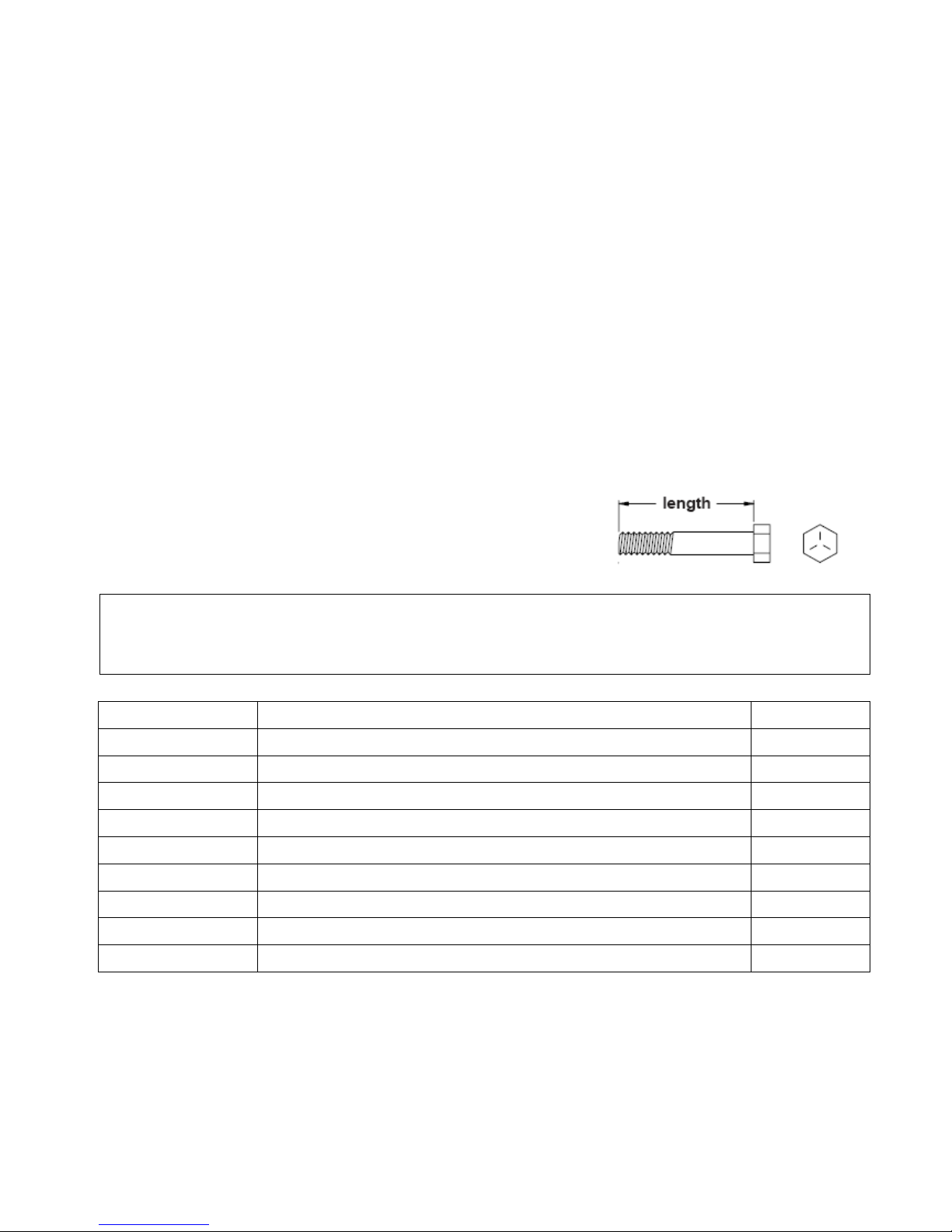
This chart below is provided to help identify the hardware used in the assembly process.
Use the circles below to confirm the diameter of each Washer, Bolt and Screw.
Use the small ruler to check the length of the bolt and screw.
NOTICE: The length of the bolt or screw DOES NOT the
head to the bolt or screw.
After unpacking the unit, open the hardware bag and make sure that you have all the
following items. Some
hardware may be already attached to the part.
No.
Description
Q’TY
90
Lock Washer (M8)
6
95
Washer (8x23x2.0t)
2
97
Washer (8x38x2.0t)
4
103
Screw (M4x20mm)
4
108
Screw, Round Head (M5xp0.8x15mm)
19
109
Screw, Round Head (M5xp0.8x50mm)
2
114
Bolt, Socket Head (M8xp1.25x10mm)
8
120
Bolt, Button Head (M8xp1.25x16mm)
2
127
Bolt, Hex Head (M10xp1.5x50mm)
2
6
ASSEMBLE INSTRUCTIONS
Place all parts from the box in a cleared area and position them on the floor in front of
you. Remove all packing materials from your area and place them back into the box. Do
not dispose of the packing materials until assembly is completed. Read each step
carefully before beginning.
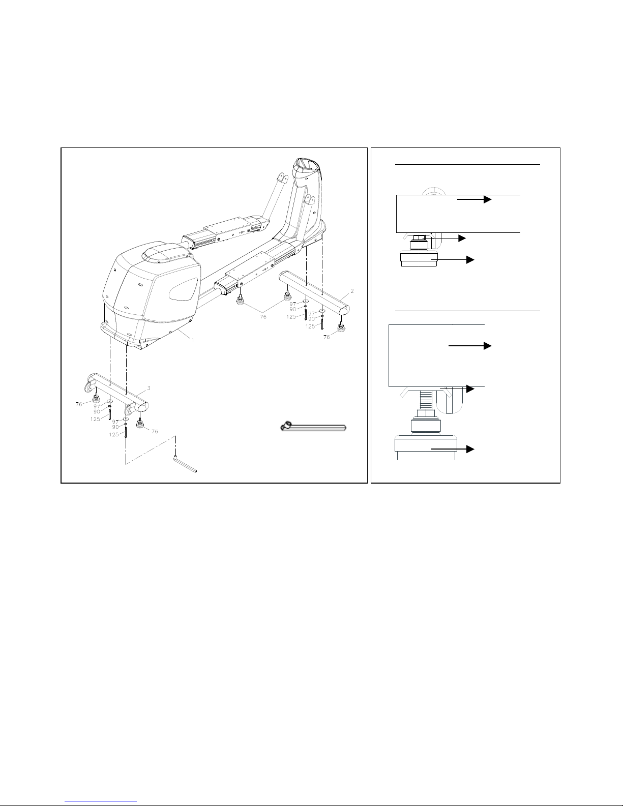
STEP 1
Attach the Floor Leveler (76) to the Front Stabilizer (2)and the Rear Stabilizer (3)
STEP 2
Attach the Front Stabilizer (2) and the Rear Stabilizer (3) to the Main Frame
Assembly (1), secure it using 4 Washers (8x38x2.0t)(97), 4 Lock Washers
(M8)(90) and 4 Hex Bolts (M8xp1.25x65mm)(125). Tighten it securely with the
socket wrench (as shown).
Adjust the Floor Leveler if the Bike is NOT leveled to the floor. Make sure the Metal
Plates are fully tightened.
Detailed Lever- drawing 1
Detailed Lever- drawing 2
Metal Plate
Stabilizer
Floor Leveler
(27)
Stabilizer
Adjustment Plate
Floor Leveler
(27)

7
STEP 3
Slide the Upright Sleeve (24) onto the Upright Post (4). Be careful not to pinch the wire
(Middle Connection Wire (138)
STEP 4
Insert 2 Nylon Lock Nuts (M10) (134) into the front of the Main Frame (1) (as
shown)
Install the Upright Post (4) to the Main Frame (1) using 2Hex Bolts (M10 x p1.5
x 50mm) (127). Secure it with the T-HANDLE SOCKET WRENCH (17MM).
STEP 5
Connect the Middle Connection Wire (138) to the Lower Connection Wire (139)
Attach the Front Decorative Cover (23) onto the front of the Main Frame (1),
secure it with 2 Screw, Round Head (M5xp0.8x50mm)(109)
Paste a Logo Sticker on the surface of the Front Decorative Cover (23). Lower the
Sleeve (24) to cover the gap on the Main Frame Housing.

8
NOTE: For shipping purpose, the Hex Bolt (M10xp1.5x55mm) (126) and Nylon Lock
Nut (M10xp1.5x8t)(134) are attached on the Pivoting Arm (L&R) (8&9).
STEP 6
a. Remove the Bolt, Hex Head (M10xp1.5x55mm) (126) and Nylon Lock Nut
(M10xp1.5x8t)(134) from the Left Pivoting Arm (8L)
b. Attach the Left Pedal Support Arm (12L) onto the Left Pivoting Arm (8) and secure
it with the Bolt, Hex Head (M10xp1.5x55mm) (126) and Nylon Lock Nut
(M10xp1.5x8t) (134.)
c. Remove the Bolt, Hex Head (M10xp1.5x55mm) (126) and Nylon Lock Nut
(M10xp1.5x8t) (134) from the Right Pivoting Arm (9)
d. Repeat the same procedure to attach the Right Pedal Support Arm (12R) onto the
Right Pivoting Arm (9)

9
STEP 7
Install the Right Inner Rotator Cuff (50mm) (148) to the outside of the Right Pivot Arm
(9.)
Attach the Right Linkage Arm (11) onto the Right Inner Rotator Cuff (50mm) (148.)
Secure it using 1 Lock Washer (M8) (90) and 1 Washer (8x23x2.0t) (95) on 1 Bolt,
Button Head (M8xp1.25x16mm) (120). Tighten it securely with the Allen Wrench.
*DO NOT over tighten it as this is a pivot point.
Install the Right Outer Rotator Cuff (50mm) (149) to the inside of the Right Pivot Arm (9)
and secure with the Screw (M4x20mm) (103) by using a Combination Wrench.

10
STEP 8
NOTE: For shipping purpose, the Bolt, Hex Head (M8xp1.25x15mm) (124) and Lock
Washer (M8) (90) are attached on the Pedal Slider (63R).
Loosen and remove the Bolt, Hex Head (M8xp1.25x15mm) (124) and Lock Washer
(M8) (90) from the Pedal Slider (63R).
Attach the bottom of the Right Linkage (11) onto the Right Pedal Slider (63R) and
secure with Bolt, Hex Head (M8xp1.25x15mm) (124) and Lock Washer (M8) (90).
STEP 9
Repeat the STEP 7 & 8 to install the Left Linkage (10) to the Left Pivoting Arm (8).
11
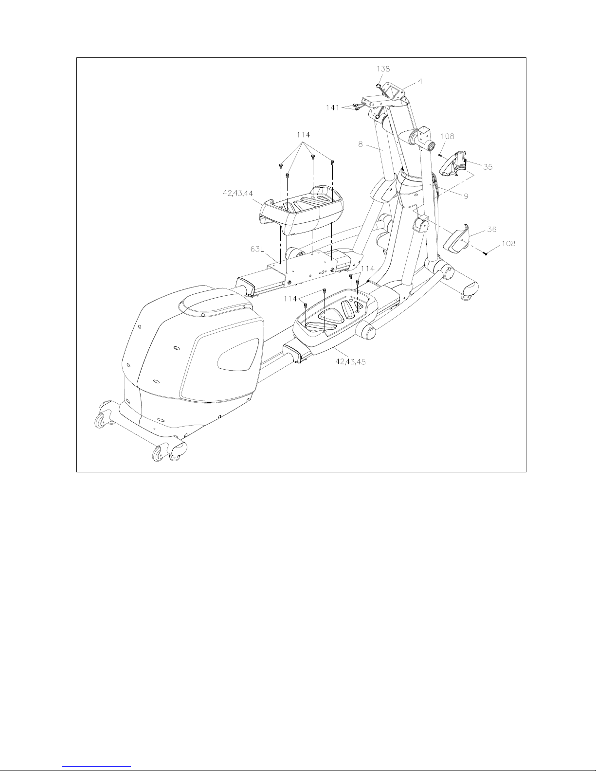
STEP 10
a. Install the Left Pivot Cuff (35) and Right Pivot Cuff (36) at both sides of the Right
Pivoting Arm (9).
b. Secure both the Left Pivot Cuff (35) and Right Pivot Cuff (36) with a Screw, Round
Head (M5xp0.8x15mm) (108).
c. Repeat the same procedure to install the Left Pivot Cuff (35) and Right Pivot Cuff (36)
to the Left Pivoting Arm (8).
STEP 11
a. Install the Left Pedal Assembly (42, 43, 44) to the Left Pedal Slider (63L) using 4
Bolts, Socket Head (M8xp1.25x10mm) (114).
b. Install the Right Pedal Assembly (42, 43, 45) to the Right Pedal Slider (63R) using 4
Bolts, Socket Head (M8xp1.25x10mm) (114).
c. Tighten all 8 bolts securely with a socket wrench (included).
12
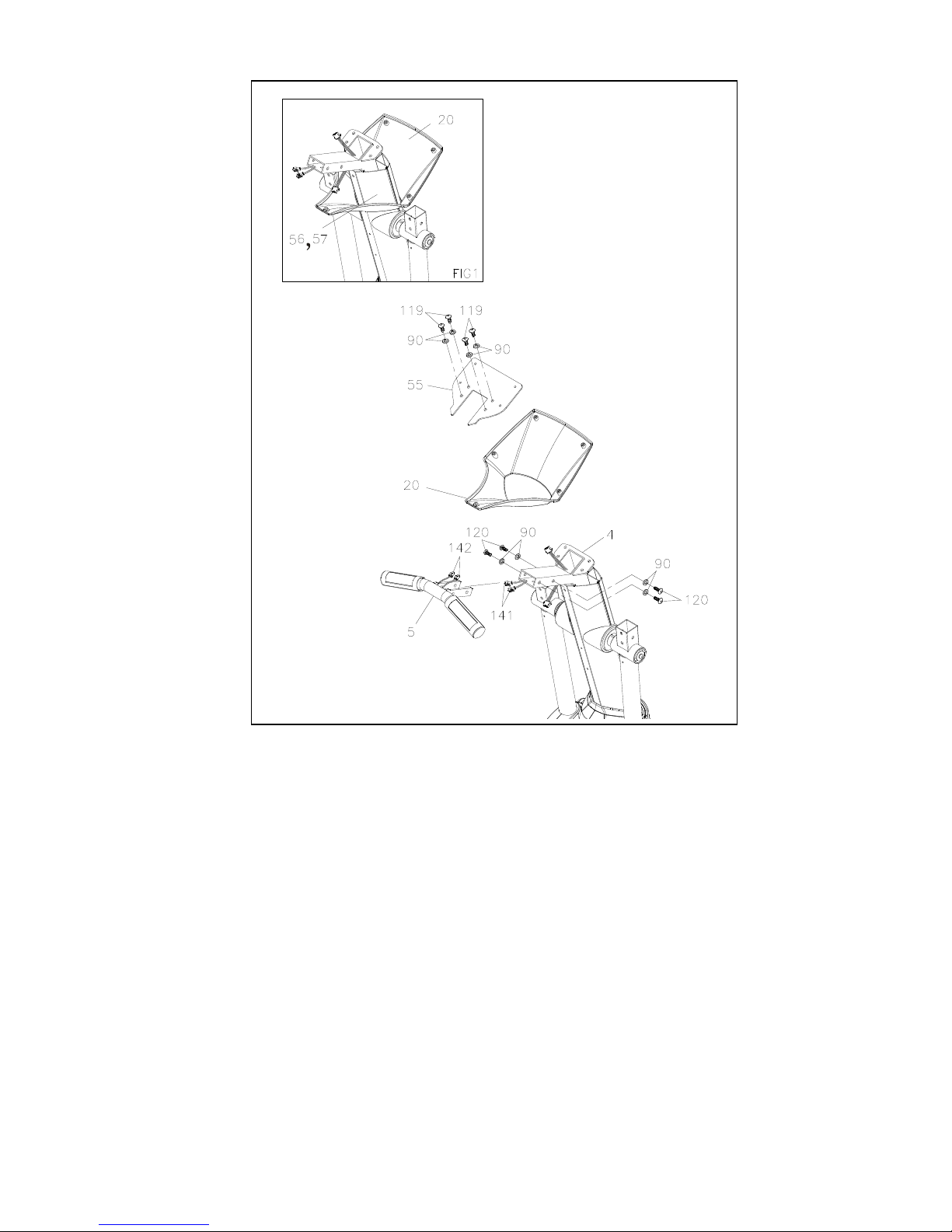
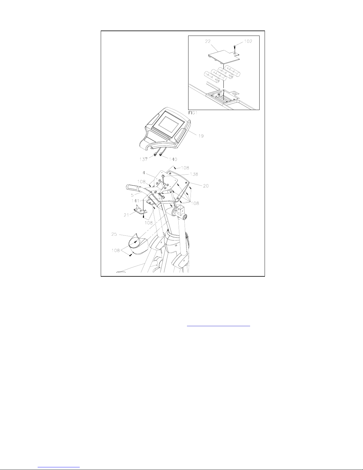
STEP 12
Slide the Console Bracket (20) onto the Front & Back Upright Cover (56, 57) (see
illustration FIG-1 above).
*Be careful not to damage the Middle Pulse Sensor Wire (141) while assembling STEP
13.
STEP 13
For shipping purpose, the Bolts, Button Head (M8xp1.25x12mm) (119) and Lock
Washers (M8) (90) are attached on the Upright Post (4).
a. Loosen and remove these 4 Button Bolts (119) and the 4 Lock Washers (90) from
the Upright Post (4).
b. Attach the Console Fixed Bracket (55) onto the Upright Post (4) and secure it with
the 4Button Bolts (119) and 4 Lock Washers (90). Tighten it securely with
Wrench.
FIG-1

13
STEP 14
The 4 Bolts, Button Head (M8xp1.25x16mm) (120) and the 4 Lock Washers (M8)
(90) are attached on the Stationary Handlebar (5).
a. Loosen and remove these 4 Button Bolts (120) and 4 Lock Washers (90) from the
Stationary Handlebar (5).
b. Connect the Middle Pulse Sensor Wire (141) and the Lower Pulse Sensor Wire
(142) to the wire in the Stationary Handlebar (5)
c. Install the Stationary Handlebar (5) to the Upright Post (4) using the 4 Button Bolt
(120) and 4 Lock Washers (90) that removed earlier.
d. Tighten it securely with Wrench (supplied)
14
STEP 15
a. Loosen the Screw (M3x10mm) (102) from the back of the Display Console using the
Philips Screwdriver then remove the Battery compartment cover (22).
b. Install 4 AA batteries (included). Regular battery may damage the Display Console,
please only use the Rechargeable NIMH (Nickel-metal hydride) batteries.
c. Re-attach the Battery Compartment cover (22) to the back of the Display Console
(19) and secure it with the Screw (M3x10mm) (102).
STEP 16
a. Connect the Upper Pulse Sensor Wire (140) to the Middle Pulse Sensor Wire (141).
b. Connect the Upper Connection Wire (137) to the Middle Connection Wire (138).
STEP 17
a. Install the Display Console (19) onto the Upright Post (4), secure it using 4Screws,
Round Head (M5xp0.8x15mm) (108),
b. Attach the Console Lower Case (21) to the Console (19) underneath the Handlebar
(5), secure it with aScrew, Round Head (M5xp0.8x15mm) (108).

15
STEP 18
Install the Console Bracket (20) onto the Console (19), secure it with 4 Screws, Round
Head (M5xp0.8x15mm) (108).
STEP 19
Remove the 2 Screws, Round Head (M5xp0.8x15mm) (108) that attached to the
Upright Post (4)
Install the Water Bottle Holder (25) onto the Upright Post (4) and secure it with the 2
Screws that removed earlier.

16
STEP 20
a. Loosen and removed the 8 Bolts, Button Head (M8xp1.25x16mm) (120) and 8
Lock Washers (M8) (90) from the Left and Right Upper Handlebar (6, 7).
b. Slide the Left Upper Handlebar (6) into the Left Pivot Arm (8L) secure it using 4Bolts,
Button Head (M8xp1.25x16mm) (120) and 4 Lock Washers (90)
c. Repeat the same procedure to install the Right Upper Handlebar (7) to the Right Pivot
Arm (8R).
STEP 21
a. Place the Front and Rear Pivot Arm Cover (33 & 34) to the Right Pivot Arm (9)
b. Using 2Screws, Round Head (M5xp0.8x15mm) (108). Tighten it securely with a
Philip Screwdriver.
c. Repeat the Same procedure to install the Left Pivot Arm (8)
Tighten all Nuts and Bolts with Wrenches.

17
OPERATIONS INSTRUCTIONS
CONSOLE ANGLE ADJUSTMENT
The Display Console angle may be adjusted by
pushing the A or B on the Display Console
TRANSPORT YOUR ELLIPTICAL TRAINER SAFELY
Lift up the front end of the machine by grip and hold the Front Stabilizer (2) with both
hands, transport the Elliptical Trainer on wheel slowly.

18
HOW TO INSTALL AND REPLACE BATTERIES:
Loosen the Screw (83) at the bottom on the Console Bracket (14).
Loosen the Screw (M3x10mm)(79) that locks the battery cover.
Install (or Replace) only the Nickel-Metal Hybrid/NI-MH rechargeable batteries.

19
PARTS LIST
NO.
Description
Q'TY
1
Main Frame
1
2
Front Stabilizer
1
3
Rear Stabilizer
1
4
Upright Post
1
5
Stationary Handlebar
1
6
Left Upper Handlebar
1
7
Right Upper Handlebar
1
8
Left Pivoting Arm
1
9
Right Pivoting Arm
1
10
Left Linkage
1
11
Right Linkage
1
12
Pedal Support Arm
2
13
Front Left-Side Cover
1
14
Front Right-Side Cover
1
15
Rear Left-Side Cover
1
16
Rear Right-Side Cover
1
18
Main Frame Base Cover
1
19
Console
1
20
Console Bracket
1
21
Console Lower Case
1
22
Battery Door
1
23
Front Decorating Upright Cover
1
24
Upright Sleeve
1
25
Accessory Tray
1
26
Pulse Sensor Top Housing
2
27
Pulse Sensor Bottom Housing
2
28
Pulse Sensor Plate Assembly
4
29
Foam Grip Assembly (40mm)
2
30
Stationary Handlebar Plug (ψ31.8mm)
2
31
Foam Grip Assembly (225mm)
2
32
Inner Rotator Cuff-Pivoting Arm
2
33
Front Rotator Cuff-Pivot Arm
2
34
Back Rotator Cuff-Pivoting Arm
2
35
Left Pivot Cuff
2
36
Right Pivot Cuff
2
37
Inner Rotator Cuff-Linkage
6
Table of contents
Other TKO Elliptical Trainer manuals


