TMI Products BELAIR-SC8 User manual
Owner’s Manual
BELAIR-SC8
Portable Heavy Duty
Self-Contained Extractor

CAUTION
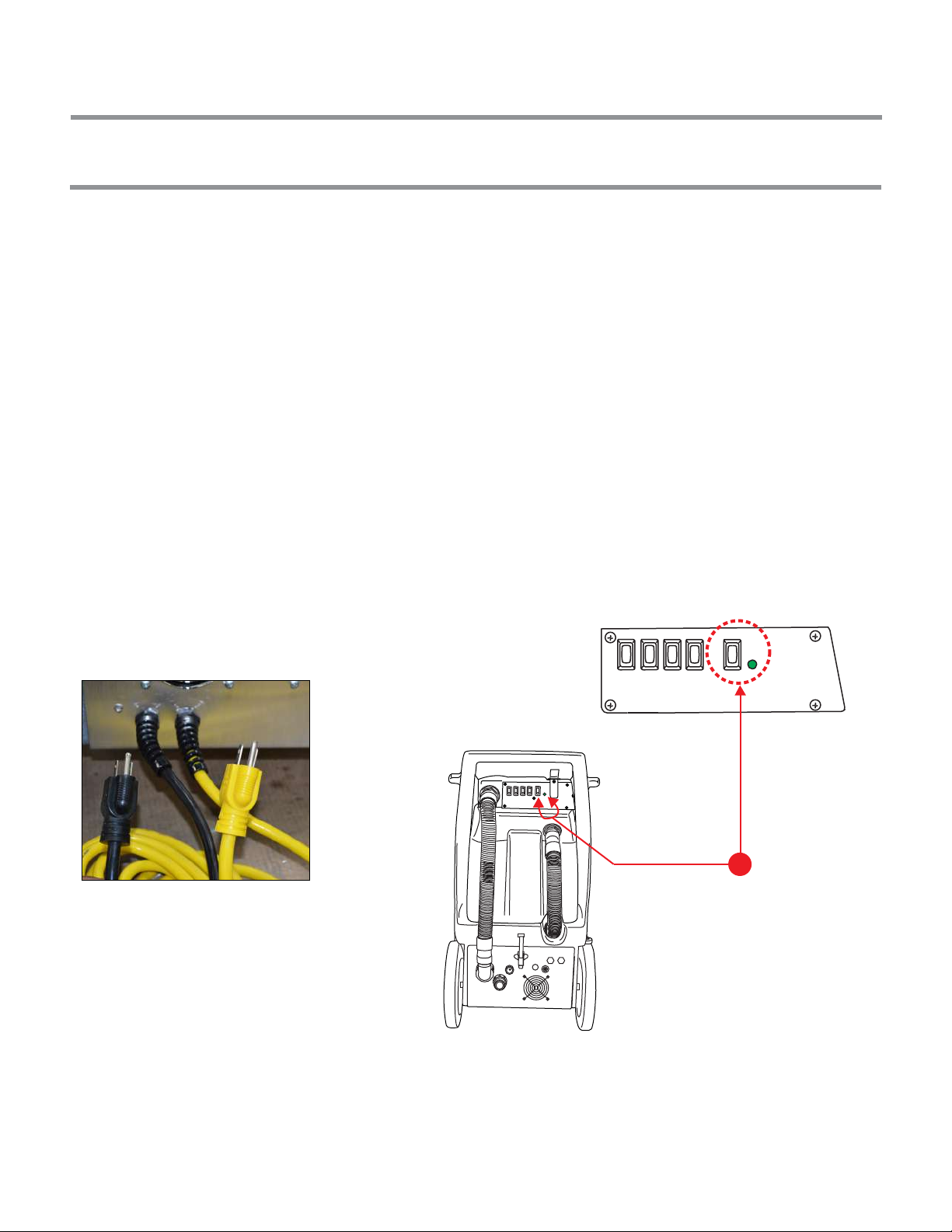
Make sure the power cord is plugged into an electrical outlet with the appropriate voltage. (As shown on the
extractor). Each power cord must be on separate circuits. To test if the extractor is on two separate circuits press the
“Circuit Test” switch located on the switch plate. If the green light is illuminated it will confirm that the extractor is on
two separate circuits. If the green light is not illuminated this indicates that the extractor is on the same circuit, and
that the user must find an additional circuit to plug the other power cord.
Warning!
This extractor is designed for use on carpet, floor and upholstery applications as per instructions written in this manual.
Any deviation from its proper use or purpose and the consequential damage that may occur is the sole responsibility of
the end user.
Do not attempt to repair the extractor. See your authorized service dealer.
Do not expose extractor to extreme temperatures.
Do not use unauthorized replacement parts.
This extractor was tested before shipping and antifreeze may remain in the plumbing system. The user must flush out
the antifreeze before use. Make sure to use antifreeze if storing the extractor in extremely cold weather.
2
Dual Power Cord Extractors
Single Power Cord Extractors
GENERAL PRECAUTIONS FOR SINGLE AND DUAL POWER CORD EXTRACTORS:
Make sure the extractor is plugged into an electrical outlet with the same voltage as shown on the extractors

TABLE OF CONTENTS
3
CAUTION 2
TABLE OF CONTENTS 3
LIMITED WARRANTY 4
WARRANTY REGISTRATION 5
Owner’s warranty information
SAFETY INSTRUCTIONS 7
EXTRACTOR OVERVIEW 8
ASSEMBLY 9
Connect power, Connect hose
OPERATING THE EXTRACTOR: 11
Before operating
Operating
After operating
PREVENTATIVE MAINTENANCE 14
HOW TO: 15
How to open the unit
How to adjust the height of the wheels
How to adjust the motor drive belt
How to use attachment tools
How to bleed the system
System without electric instant water heater
System with electric instant water heater
OPTIONS: 19
Chemical feed & Mixing system
Adjustable chemical feed system
Metering tips preset chemical feed system
Electric instant water heater (Inline heater)
Tank heater (bottom mount)
TROUBLESHOOTING: 23
Electrical system
Pump system
Vacuum system
Heating system

LIMITED WARRANTY
4
All equipment and accessories are thoroughly inspected and tested before leaving the factory. They are warrantied to
be free of defects from workmanship and materials for one year from date of original purchase. (proof of purchase is
required).
Labor: 90 days from initial purchase
Parts: 1 year, excluding normal wear and tear items
Heavy duty fiber composite body: 20 years limited warranty
Polyethylene body: 5 years limited warranty
Should any trouble develop during this period, please contact your dealer or manufacturer to receive a Return
Guarantee Authorization number (RGA #). Return the part or extractor that need to be replaced. If after an inspection
it is determined to be under warranty, the factory will repair or replace (manufacturer’s discretion) the parts or
equipment and return parts or equipment at no charge. Note: Credit, repair or replacement will not be given to any
parts or equipment without the above mentioned RGA#.
Proof of purchase is necessary to establish the date of the original sale. Receipt of purchase or warranty registration
can be used as proof of purchase. It is important to register your purchase by sending the warranty registration form
within 10 days of purchase.
This warranty is in lieu of all other warranties expressed or implied, and no person is authorized to give any other
warranty, assume obligation or liability on the manufacturer’s behalf.
This Warranty does not apply when:
- Repairs that are required because of normal wear and tear
- Repairs have been made or attempted by others
- Items have been abused, misused or improperly maintained
- Modifications or alterations have been made to the equipment
In no event shall seller be liable for any incidental, consequential or special damages of any kind or nature
whatsoever. Including but not limited to lost profits arising from or in anyway connected with this agreement or items
sold hereunder, whether alleged to arise from breach of contract, express or implied warranty, or in tort, including
without limitation, negligence, failure to warn or strict liability.
LIMITATION OF REMEDY:
This agreement and warranty shall be governed in all respects by the law of the State of Massachusetts. No actions
arriving out of the items sold hereunder or this Agreement may be brought by either party more than two (2) years
after the cause of action occurs. All mediation or litigation will take place in the County of Middlesex in Massachusetts.
ENTIRE AGREEMENT / GOVERNING LAW:

BLANK PAGE
5

SAFETY INSTRUCTIONS
WARNING!
When using an electrical appliance, basic precautions should always be followed.
To reduce the risk of fire, electric shock or injury following these tips:
1. Do not leave appliance plugged in. Unplug from outlet when not in use.
2. Electric shock could occur if used outdoors or on wet surfaces.
3. Keep away from children. Extractor is not to be used as a toy.
4. Use only as described in this manual. Use only manufacturer’s recommended parts.
5. Do not use extractor with damaged power cords.
6. Do not abuse the power cord. Do not pull or carry extractor with the power cord. Do not use the power cord
as a handle. Do not close doors on the power cord. Do not pull power cord around sharp edges or corners.
Do not run the extractor over the power cord. Do not keep power cords around heated surfaces.
Do not unplug by pulling on electric power cord. To unplug, grasp the plug, not the electric power cord.
7. Do not handle plug or appliance with wet hands.
8. Do not put any object into openings. Do not use with any opening blocked; keep free of dust, lint, hair and
anything that may reduce air flow.
9. Keep hair, loose clothing, fingers and all parts of body away from openings and moving parts.
10. Do not pick up anything that is burning or smoking, such as cigarettes, matches or hot ashes.
11. Do not use extractors without filters.
12. Turn off all controls before unplugging from electric outlet.
13. Use extra care when cleaning on stairs.
14. Always wear safety equipment and appropriate clothing when operating the extractor.
15. Do not use extractor to pick up flammable or combustible liquids such as gasoline or use in areas where such
items may be present.
16. Connect to a properly grounded electric power outlet only.
17. Do not attempt to service the extractor while appliance is plugged in.
6
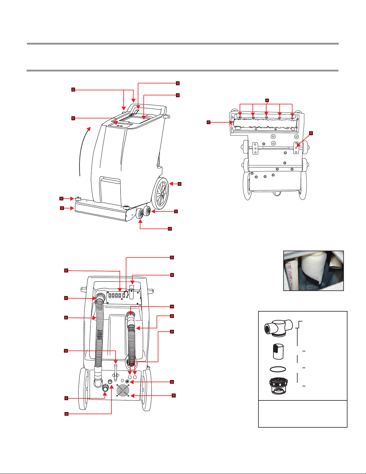
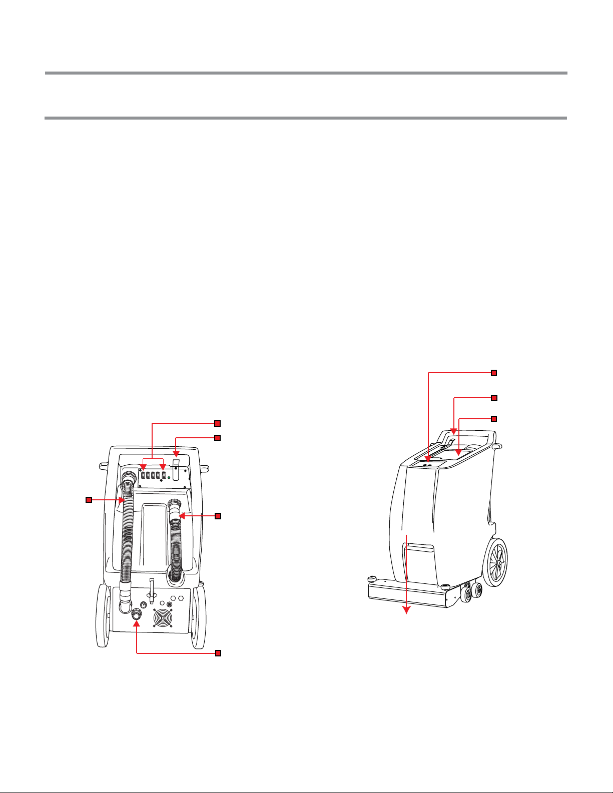
EXTRACTOR OVERVIEW
7
Solution tank lid
Recovery tank lid
Drain connect
Drain hose
Inline filter
(solution)
A. Electric power cords
(standard model comes
with a single power cord)
B. For a 2-3 stage vacuum motor
unit or with heater, two power
cords are required (optional)
Draw latch
Vent screen
Two circuit “TEST SWITCH”
(only with two power cords unit)
Hand grip
& cord winder
Spray trigger
Extractor
head
Wall
protector
Spray trigger
Solution
output
Power head
brush switch
Vacuum
hose
connect
Reset switch
(for units with optional heater)
Middle wheels
Front wheels (adjustable)
Transport
rear wheels
Dirty water
recovery
hose
(vac hose)
Wet vacuum filter
inside recovery tank
[Part #: PM10150]
Image 7.4
Image 7.2
Image 7.1
Image 7.3
Solution filter on
bottom back panel
Image 7.5
B
C
1/4” = TF101050
(complete set)
TF105016
TF105015
TF105020
D
Bottom view
Wheel height
adjustment bolt
5 Jets
Rotary brush

ASSEMBLY
8
CONNECT ATTACHMENT HOSE (how to connect optional wand and hoses)
Disconnect the unit vacuum hose from hose connect. (Image 8.2)
The solution hose has a male quick connect on one end and a female quick connect on the other end. (Image 8.3)
This unit can operated in two different ways, use it with power head or with an optional
attachment tool and hoses.(see below images)
IMPORTANT TO KNOW
CONNECT ELECTRIC POWER CORD
Protect the ground plug. This plug is to be used with a proper grounding type (three prong) receptacle. Do not break
off or pull out the grounding blade. (see below image)
Ground blade (DO NOT break off)
Three prong receptacle
Image 8.1
Disconnect vacuum
hose from vacuum
hose connect
Optional attachment tool
Image 8.2
Image 8.3
- Vacuum hose connection to attachment tool
- Solution hose connection to attachment tool quick connector
- Solution hose line
Connect solution hose
to unit quick connect
Connect vacuum hose
to attachment tool
Connect vacuum hose
to intake connection
Connect solution hose
to attachment
tool quick connect
OPERATING THE EXTRACTOR
BEFORE OPERATING:
9
Read the manual carefully and completely before attempting to operate the extractor. Make sure the unit is plugged
into an electrical outlet with the same voltage as shown on the extractor.
1. When plugging in a dual power cord extractor (see below image 9.1); each power cord should be connected on two
separate circuits. When this is accomplished, a green light will turn on, when the “Circuit Test Switch” is pressed on the
switch plate. If the light does not turn on, this indicates that the unit not connected on two separate circuits and there
is a high risk of a circuit blowout.
2. Always thoroughly pre-vacuum the surface to be cleaned. Using an upright vacuum cleaner (or the extractors dry
vacuum with optional dry attachment).
3. Pre-spray the cleaning area with recommended cleaning solution for the best results.
4. Fill solution tank with clean water.
5. Connect both the vacuum hose and solution hose to the proper connections. See image on “Assembly” page.
6. Make sure the drain hose is closed and the recovery tank lid is secured before turning on the vacuum and pump
switches.
Two electric power cords must be
connected to two separate circuits.
Image 9.1
“Circuit test switch” is located next to the green light.
Press the switch button to test the current of the two cords
if the light turns on it means that the cords are on two separate
circuits if the light does not turn on it means that the cords are
on the same circuit.
Detail view of
circuit test switch
B
Image 9.2
Image 9.3
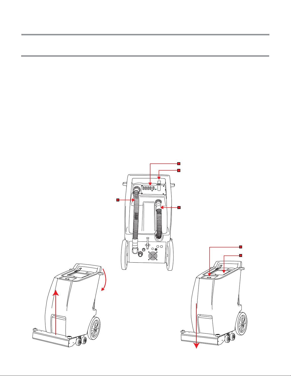
OPERATING THE EXTRACTOR
DURING THE OPERATION: using the power head
10
1. Make sure the recovery hose is connected to the extractor, from the recovery tank connection to the vacuum
connection.
(see below image 10.1)
2. Make sure drain hose is connected (see image 10.1) and recovery tank lid is closed before turning on vacuum
and pump switches. (If left open, there will be no suction)
3. Plug power cord to an electrical outlet.
4. Turn vacuum motor 1 and 2 on.
5. Turn pump on.
6. Turn heaters on. (optional if the unit has heaters otherwise skip to step 6)
7. Turn brush switch on.
8. Activate spray lever as needed.
9. Push the extractor to the desired area without using force.
10. To transport the unit without cleaning (with switches off) to another area, tilt back unit on the rear wheels.
11. Continue using the machine until the water tank is empty and/or the recovery tank is full.
Recovery hose
Drain hose
Spray lever
Power head brush switch
Cleaning Position (power head touching the floor)
Move Around Position (gently tilt back on the rear wheels)
Recovery tank lid
Solution tank lid
Lower extractor
power head
Image 10.1
Image 10.2
Image 10.3
OPERATING THE EXTRACTOR
11
Note: In case that foam is detected in the recovery tank and hose, use defoamer to prevent damage to the vacuum motors.
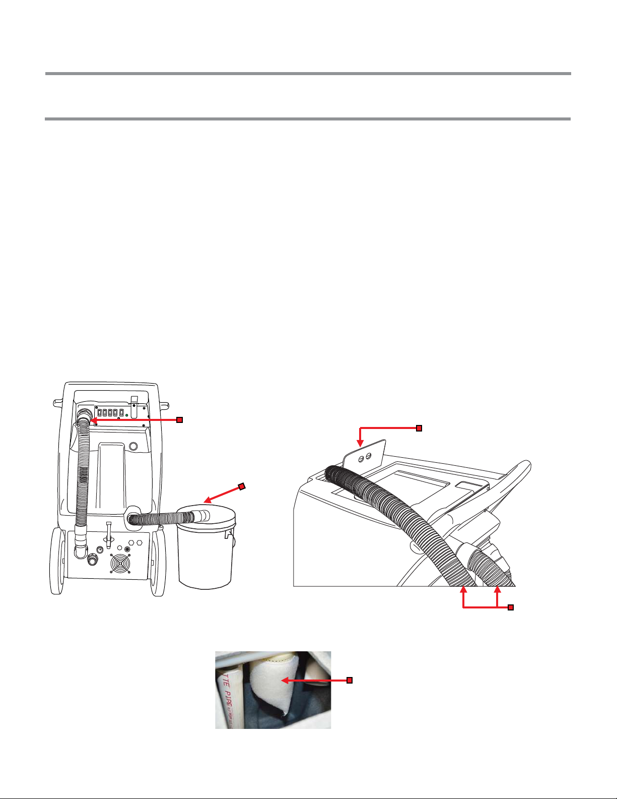
AFTER OPERATING:
Vacuum filter and ball float
cage in the recovery tank
Solution tank
3 ft. to 5 ft. long
vacuum hose
(included)
Drain hose
1. Turn all the switches off and disconnect the electric power cord from the outlet, then empty out
the recovery tank, pour the dirty water into a bucket or in a proper area. (see below image 11.1)
2. To remove the remaining water from the solution tank, you can use the same vacuum hose in the unit
(see image 11.2) and put it into the solution tank to vacuum out the remaining water.
3. Drain and thoroughly clean the recovery tank. At this point the tank can be rinsed while dumping out the water.
4. The vacuum filter (wet filter) and ball float cage have to be rinsed and cleaned thoroughly when it’s still wet. (see
below image 11.3.) See “Preventative Maintenance” page. Wrap power cords around the handle for storage.
Do not use solution or recovery tanks as storage.
Consult your sales representative for more information on cleaning methods.
Image 11.1 Image 11.2
Image 11.3
Vacuum hose
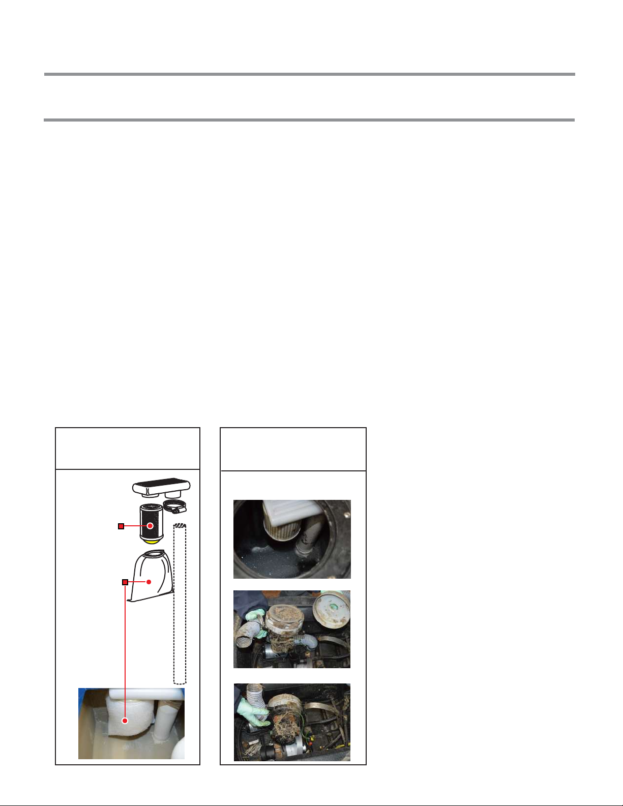
PREVENTATIVE MAINTENANCE
12
Vacuum filter
Ball float cage
NO VACUUM FILTER INSTALLED
Vacuum lter
assembly
Without vacuum
lter
The vacuum lter must be always
clean and in good condition
to protect the vacuum motor.
(See image 12.1)
Serious damage to the vacuum motors
will occur when the vacuum lter is not
installed. (See image 12.2)
Image 12.1 Image 12.2
[Part #: PM10150]
AFTER EACH USE: CLEAN, LUBRICATE, ETC...
1.Thoroughly clean all equipment and accessories after each use.
a. Rinse solution tank, recovery tank, and hoses with clean water.
b. Flush entire solution system with clean water. This includes all solution hoses and attachment tool.
Do not allow liquid with cleaning chemicals to remain in the equipment.
c. Clean all filters (Image 12.1, 12.2)
2. Lubricate all quick connects as needed.
3. Do not use the same container you use to fill the solution tank to empty the waste tank. This would result in
putting dirt and debris into the solution lines that will block filters, orifices, and generally degrade the systems.
4. Keep equipment out of extreme temperatures. (i.e. Freezing temperatures will make water expand, and will
damage pump, fittings, valves, etc.)
5. Turn off the extractor whenever is not in use. Do not walk away from the extractor while is on.
6. Check for loose or frayed wires.
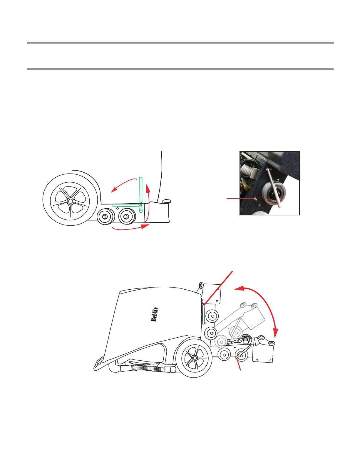
HOW TO OPEN THE UNIT
HOW TO OPEN THE UNIT
13
1. Release handle from the support lock screw. (Image 13.3)
2. (1) Bring the handle towards the front side of the unit about 90°, (2) bring the handle up about 90°, (3) bring it back
to the starting position to unlock the latch that holds the front side of the power head. (Image 13.2, 13.1)
Image 13.2
1
2
3
Image 13.1
Latch handle
locked position
Latch handle open position
Detail view of latch handle
Image 13.3
Support
lock screw

HOW TO ADJUST THE MOTOR DRIVE BELT
14
1. Place the unit on a flat surface with the back side on the floor, you will be able to see the
bottom part of the unit. (Image 14.1, 14.2)
4. Using a 7/16 wrench loosen the four hex bolts that hold the brush motor located in the bottom part of the
unit. (Image 14.2, 14.3)
5. Adjust the position of the motor as needed. (Image 14.1, 14.2)
2. Locate the adjustable bolt, it is located in the brush compartment in the head housing. (Image 14.1, 14.2 )
3. Locate the four bolts that hold the motor in the head housing. (Image 14.3, 14.2)
Image 14.1
Bottom view
Bottom view
Image 14.2
Image 14.3
Bolts holding the brush motor Bolts holding the brush motor
Drive belt
/pulley
Brush motor
Adjustable Bolt
Adjustable Bolt
Belt / pulley compartment
If replacing the motor drive belt open the compartment on the side of the power head housing (Image 14.6) using
a number 2 phillips screw driver and open the unit (page 13), you will be able to see the pulley and belt inside
the housing.
TO ADJUST THE TENSION AND/OR TO REPLACE THE BELT
Pulley and belt
Latch handle
Removable panel
Image 14.6
Image 14.4
Detail side view
with open
compartment
Image 14.5
Open unit

HOW TO USE ATTACHMENT TOOLS
WITH ATTACHMENT TOOL: (effectively)
15
Press the lever to open the valve
Valve lever
Press the lever to open the
valve during pull strokes
A BETTER TECHNIQUE WILL REDUCE FATIGUE AND IMPROVE THE QUALITY OF THE WORK
General Technique for carpet cleaning:
1. Start by pulling the wand back with the valve lever pressed on the surface (it will spray the solution).
(Image 15.2, 15.1)
2. Release the solution control valve lever (Image 15.4) and pass the tool over the dampened area once or
twice by pulling or pushing the tool back and forth. Repeat the same procedure if necessary.
NOTE: The weight of the tool and the vacuum suction are sufficient to obtain an ideal result.
Additional physical pressure is unnecessary.
Continue cleaning until the recovery tank becomes full or the solution tank becomes empty.
Image 15.3
Image 15.4
Image 15.1
Image 15.2

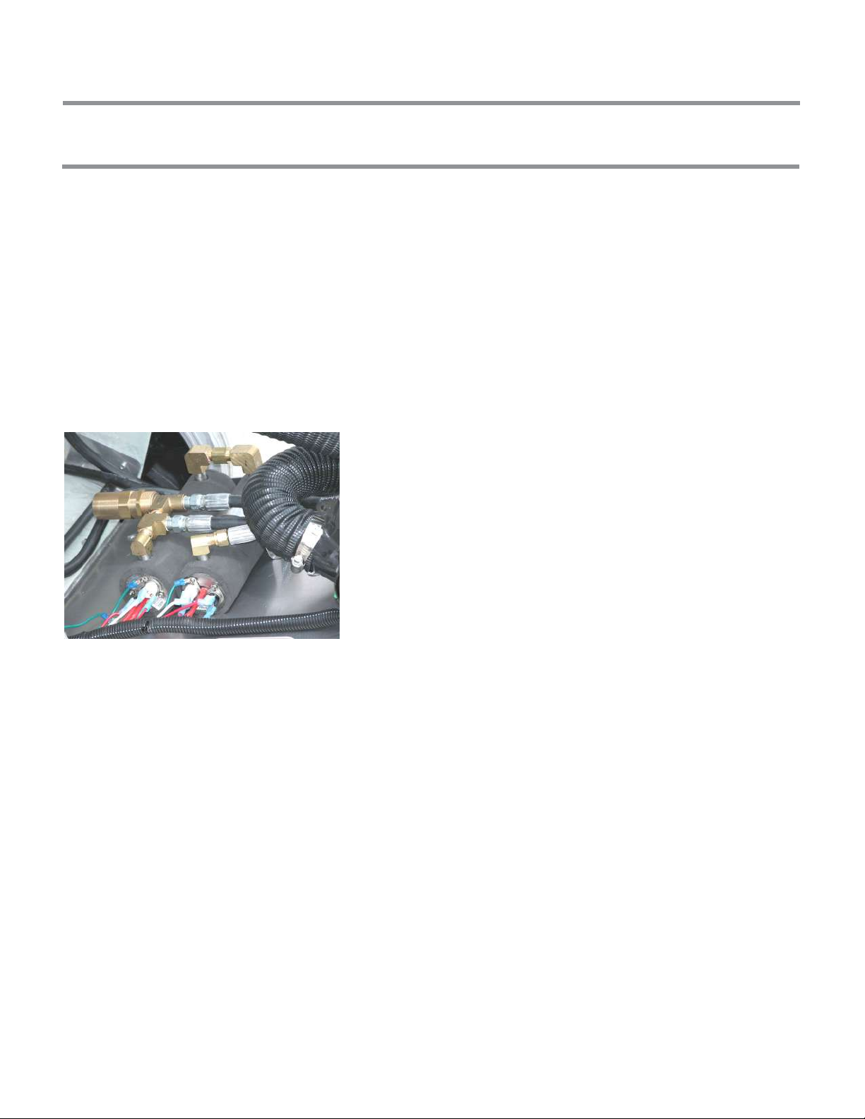
HOW TO BLEED SOLUTION LINES
WITHOUT ELECTRIC INSTANT WATER HEATER:
1. Fill solution tank with clean water.
2. Connect desired tool to the extractor with a vacuum hose and solution hose.
3. Turn pump switch “ON”.
4. Open trigger valve from the attachment tool (see Image 16.1), and spray until all air is out from the solution
system. (see Image 16.2) It might take 2-4 minutes depending on the jet size of the attachment tool.
16
WITH ELECTRIC INSTANT WATER HEATER:
WARNING: DO NOT TURN THE HEATER ON until you have followed these steps.
1. Fill solution tank with clean water.
2. Connect desired tool and extractor with a vacuum hose and solution hose.
3. Turn pump switch “ON”.
4. Open the trigger valve on the attachment tool (see Image 16.1), and spray until all air is out from the solution
system. (see Image 16.2) It might take 2-4 minutes depending on the jet size of the attachment tool.
5. Turn heater switch on and wait approximately 3-4 minutes to heat up. Now the unit is ready to use with the
heater.
Press the lever to open the valve
TMI
MADE IN U.S.A.
Once the line is clear
of air you will start to
see water comming out
Image 16.1
Image 16.2
(extractor with optional attachment tool )
HOW TO BLEED SOLUTION LINES
WITHOUT ELECTRIC INSTANT WATER HEATER:
1. Fill solution tank with clean water.
2. Turn pump switch “ON”.
4. Open the spray trigger valve on the extractor (see Image 17.1), and spray until all air is out from the solution
system. It might take 2-4 minutes depending on the jet size of the extractor power head.
17
WITH ELECTRIC INSTANT WATER HEATER:
WARNING: DO NOT TURN ON THE HEATER until you have followed these steps.
1. Fill solution tank with clean water.
2. Turn pump switch to “ON”.
4. Open the spray trigger valve on the extractor (see Image 17.1), and spray until all air is out from the solution
system. It might take 2-4 minutes depending on the jet size of the extractor power head.
5. Turn heater switch on and wait approximately 3-4 minutes to heat up. Now the unit is ready to use with the
heater.
(extractor without optional ATTACHMENT)
Recovery
hose Drain hose
Spray trigger
Power head switches
Image 17.1
Inline filter
(solution)
Cleaning Position (lower position of power head)
Recovery tank lid
Solution tank lid
Lower extractor
power head
Image 17.2
Spray trigger

HOW TO ADJUST THE WHEELS HEIGHT
ADJUST THE WHEELS FOR DIFFERENT CARPETS
18
FOR DELICATE CARPETS:
FOR COMMERCIAL CARPETS:
USING THE POWER HEAD
Image 18.1
Image 18.2
(Commercial carpets are usually made of thick material
for durability and resistance)
(Delicate carpets are usually made of thin material and
might not be resistant when aplying too much pressure
with the rotary brush or to excessive heat.)
Image 18.3
Image 18.4
Transport wheels
Non-adjustable wheels
Front adjustable wheels
Cleaning power head
Adjust the wheel height with a 7/16 wrench, tightening the
bolt clockwise to lower the wheel or counterclockwise
to raise it.
1. Place middle operation wheel into
lower position
2. Use a 7/16 wrench to tighten the bolt
clockwise (see image 18.2)
3. Do the same procedure to the other side
1. Place middle operation wheel into
higher position
2. Use a 7-16 wrench to tighten the bolt
counterclockwise (see image 18.2)
3. Do the same procedure to the other side
1. HOW TO USE UNIT WITH ELECTRIC INSTANT WATER HEATER (Inline heater)
19
HEATERS (OPTIONAL)
1. Fill solution tank with clean water.
2. Connect desired attachment tool (optional)
3. Turn pump switch ON.
4. Bleed the line. (see “How to Bleed solution lines” page 16, 17.)
5. Turn heater switch “ON” and wait approximately 3-4 minutes to heat up.
♦ The inline heater has a pre-set thermostat for 210° F.
♦ Keep solution tank clean and do not use any flammable products.
♦ Water level should always be over the level switch by a least two inches. (system with level switch)
Image 19.1
Inline heater

TROUBLESHOOTING
20
PROBLEM POSSIBLE CAUSE HOW TO REPAIR
No electrical power 1. No power on outlet 1. Plug in properly
2. Damaged cord 2. Contact TMI
3. Circuit breaker off or fuse blown 3. Flip circuit breaker on or replace
fuse. Unplug orther equipment
using the same circuit. Make sure
cords are plugged into a proper
circuit
Switch is turned on, power
is intermittent to all motors 1.Faulty electrical cable 1. to 3: Contact TMI
2. Defective switch
3. Loose terminal or corroded
connector
Electric shock 1. Equipment not grounded 1. Contact TMI
PROBLEM POSSIBLE CAUSE HOW TO REPAIR
Pump motor stopped 1. Pressure build up caused by 1. Release pressure by opening up
a clogged jet. (press) the lever on the Wand.
2. Thermal overload (over heated) 2. Turn off the pump and heater
switch and wait 20 - 30 minutes
for the pump to cool down. Make
sure vent area is free from any
objects or debris
3. Damaged motor or rectifier 3. to 7: Contact TMI
4. Pump switch defective
5. Loose wire connection
6. Pump pressure switch defective
7. Faulty motor
Loss of pump pressure with wand
valve open and/or uneven or weak
spray from the jet tips 1. Clogged or dirty spray tip 1. Clean jets and screens
2. Accumulated dirt in solution line 2. Clean
3. Dirty or clogged filters 3. Clean
4. Pump check valve worn or dirty 4. to 6: Contact TMI
5. Malfuction in the wand valve
6. Hose quick connect bad or
clogged with lint.
ELECTRICAL SYSTEM
PUMP SYSTEM
Table of contents
Popular Ventilation Hood manuals by other brands

Gorenje
Gorenje S3 IHGC963S4X manual

KOBE
KOBE ISX2136SQB-1 Installation instructions and operation manual

U.S. Products
U.S. Products ADVANTAGE-100H Information & operating instructions

Kuppersberg
Kuppersberg DUDL 4 LX Technical Passport

Framtid
Framtid HW280 manual

Thermador
Thermador HGEW 36 FS installation manual


