TOELLNER TOE 9260 Series User manual

TOELLNER Electronic Instrumente GmbH
09.10.2014
Application Note No. 9260
-
001
Power and Signal Line Interruptions
for Automotive Tests
Electronic Switch TOE 9260
9260E-AN001_Rev00.doc
R
TOELLNER ELECTRONIC INSTRUMENTE GMBH
Gahlenfeldstrasse 31, 58313 Herdecke, Germany
+49 (0) 23 30 - 97 91 91 • Fax +49 (0) 23 30 - 97 91 97
E-Mail: info@toellner.de • Web: www.toellner.de
Subject to technical changes

Contents
Page
TOELLNER Electronic Instrumente GmbH
2
1.
Introduction.............................................................................................................3
1.1
Required test equipment .......................................................................................................3
2.
Tests according to standard LV 124.....................................................................5
2.1
LV 124, E-10, Short interruptions..........................................................................................5
2.2
E-10, Short interruptions ‒reference measurements............................................................6
2.3
LV 124, Test E-13, Pin interruption .......................................................................................6
2.3.1
E-13, interruption of signal pins..........................................................................................6
2.3.2
E-13, interruption of signal pins ‒reference measurements...............................................7
2.3.3
E-13, interruption of ground pins ........................................................................................8
2.3.4
E-13, interruption of ground pins ‒reference measurements.............................................8
3.
Tests according to standard LV 148...................................................................10
3.1
LV 148, E48-09, Short interruptions ....................................................................................10

TOELLNER Electronic Instrumente GmbH
3
1. Introduction
The Electronic Switch TOE 9260 is a device for time-based turning on and off of load and
signal currents. This device provides an electronic, unidirectional power switch as well as
four electronic bidirectional signal line switches. The power switch incorporates a selectable
load-parallel crossover for selective discharging of buffered loads.
A digital input signal can be used to generate on- and off-durations of any time down to the
microsecond range for both the power switch and the signal line switches.
By these features, the TOE 9260 especially is applicable for the following tests according to
the automotive standards LV 124 and LV 148:
•LV 124, E-10: Short interruptions
•LV 124, E-13: Pin interruption
•LV 148, E48-09: Short interruptions
There are many other industry standards based on LV 124 and LV 148 like VW 80000,
GS 95024-2, VW 82148, etc. with power and signal line interruptions, where the Electronic
Switch TOE 9260 can be applied.
Subject of this document is how these tests are carried out by use of the TOE 9260,
especially under consideration of the following points:
•Test assembly and wiring of the components
•Choice of the right switch, i.e. power switch resp. signal line switch of the TOE 9260
•Reference measurements according to the requirements of the LV 124-2013
1.1 Required test equipment
Commonly the following components are needed for the test assemblies:
•DUT (Device under Test)
•Power supply according to the requirements of the Device under Test
•Electronic Switch TOE 9260
•4x high current cable (cross section 16 mm²) with connector KBT6AR-N/16-S
(Manufacturer: Multi-Contact) to connect the power supply and the DUT to the power
switch of the TOE 9260.
Note
Please note, that the connector KBT6AR-N/16-S can only be mounted to a cable by use of
special tooling, soldering is not possible.
The use of the following connection cables of length 1,20 m or 0,50 m
TOE 9260/22 (Red) and TOE 9260/23 (Blue) is recommended:
Item No.
Item name
TOE 9260/22 0.50 m connection cable with 1 safety socket, red
TOE 9260/23 0.50 m connection cable with 1 safety socket, blue
TOE 9260/24 1.20 m connection cable with 1 safety socket, red
TOE 9260/25 1.20 m connection cable with 1 safety socket, blue
•Pulse source, e.g. Arbitrary Function Generator TOE 7761, or a DAQ-card with digital
outputs
•PC as control device for the function generator or DAQ-card to generate the pulse
sequences especially for the tests LV 124 E-10 resp. LV 148 E48-09
•Oscilloscope or fast data logger for evaluation of the measurement results

TOELLNER Electronic Instrumente GmbH
4
When performing tests according to LV 124-2013, additionally:
•Reference resistors 1 Ω, 100 Ω, and 1 kΩof low inductance, ±5% tolerance to perform
reference measurements. The use of the following reference resistor kits is
recommended:
Item No.
Item name
TOE 9260/100 Reference Resistor Kit 1 Ω, 100 Ω, and 1 kΩfor power switch
TOE 9260/104 Reference Resistor 1 Ω/ 1 kΩfor signal line switches

TOELLNER Electronic Instrumente GmbH
5
2. Tests according to standard LV 124
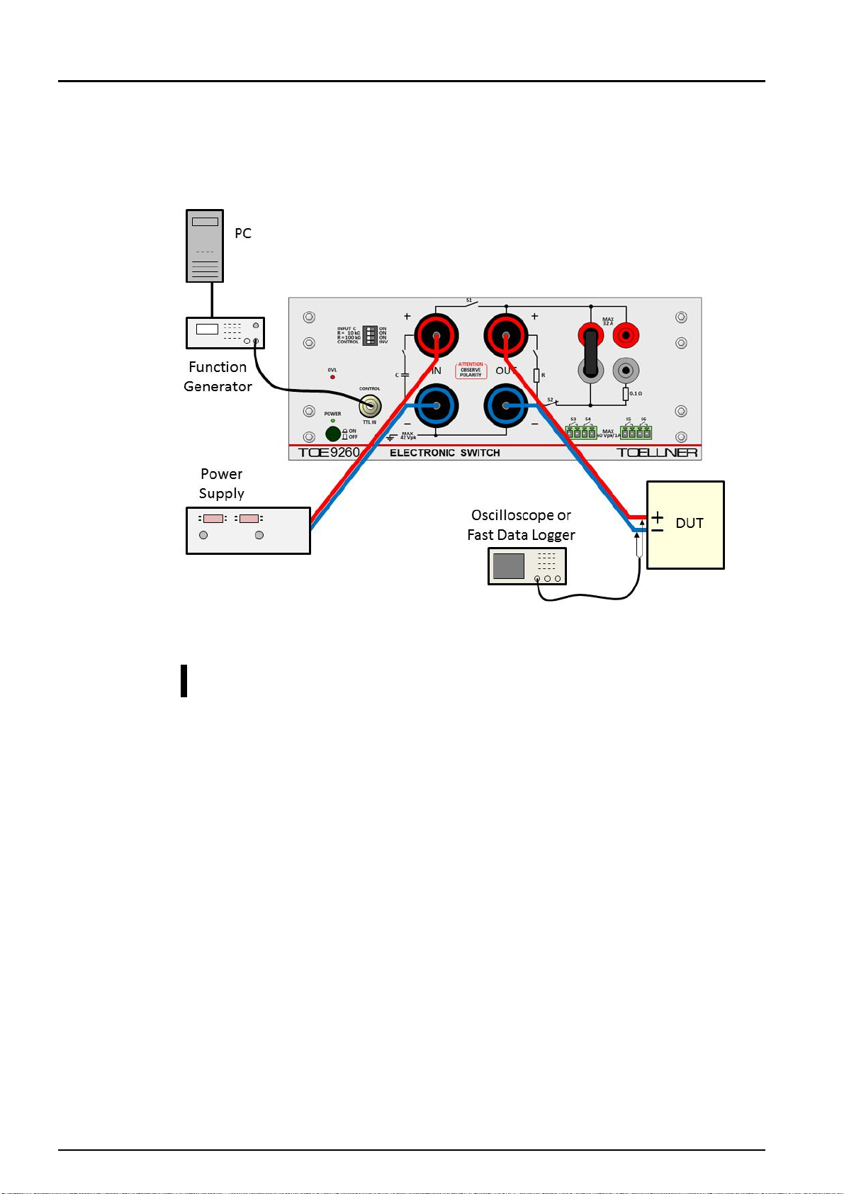
2.1 LV 124, E-10, Short interruptions
Test E-10 shall be applied to power supply lines of the DUT.
The test assembly for the test E-10 is shown in Fig. 1. With the connecting plug placed as
shown, the assembly is configured for test case 2. For test case 1 the connecting plug has to
be removed or placed in a neutral position, i.e. socket pair red – red or gray – gray.
Fig. 1: Test assembly for LV 124, E-10
Note
The important points for test execution in line with the requirements of the standard aim at
the wiring as explained in the following:
•The cross section of the cables must fit to the drawn current. For currents up to 100 A
please use the cables TOE 9260/22 and TOE 9260/23 (length 0.50 m) resp.
TOE 9260/24 and TOE 9260/25 (length 1.20 m).
•The two wires from the power supply to the IN sockets of the TOE 9260 have to be laid
as closely spaced as possible (e.g. twisted) to reach minimum inductance values.
•As long as no artificial network is applied between the power supply and the IN sockets of
the TOE 9260, the internal capacitor at the input of the TOE 9260 should be activated by
setting the DIP switch “INPUT C” to “ON”. So the shortest possible rise and fall times of
the voltage at the DUT are achieved.
•If an artificial network between the power supply and the IN sockets of the TOE 9260 is
necessary, the internal capacitor at the input of the TOE 9260 must be deactivated by
setting the DIP switch “INPUT C” to “OFF”. In that case the two wires from the artificial
network to the IN sockets of the TOE 9260 have to be laid as closely spaced as possible
(e.g. twisted) and also kept as short as possible to get short rise and fall times at the
DUT.
•Also the two wires from the OUT sockets of the TOE 9260 to the DUT have to be laid as
closely spaced as possible (e.g. twisted). Any additional cable inductance will act as an
inductive filter together with the resistance and / or capacitance of the DUT, which results
in increased rise and fall times measured at the DUT.
•If the DUT has to be connected by a wiring harness or if a wiring harness is part of the
DUT, the said remarks are valid for the cables from the OUT sockets of the TOE 9260 to
the start point of the wiring harness.

TOELLNER Electronic Instrumente GmbH
6
2.2 E-10, Short interruptions ‒reference measurements
This section applies to LV 124, version 2013 only. That standard requires reference
measurements before an interruption test is carried out with the DUT. Such a reference
measurement gives proof of the slew rate of the switching operation. For the reference
measurements of the E-10 test the DUT is replaced by a reference resistor of 1 Ω± 5 %
resp. 100 Ω± 5 % of low parasitic inductance (Fig. 1).
To avoid the addition of cable inductivity, the reference resistor shall be connected as close
to the output sockets of the TOE 9260 as possible. The reference resistors of the
TOE 9260/100 kit may be connected directly to the output sockets without use of cables.
Because of the high power loss in case of the 1 Ωresistor operated at 11 V according to the
LV 124, the test setup should be prepared in the powerless state. Test execution should be
kept as short as possible.
2.3 LV 124, Test E-13, Pin interruption
The test E-13 has to be applied to signal pins as well as to ground pins. For both situations,
the test assemblies are explained in the following.
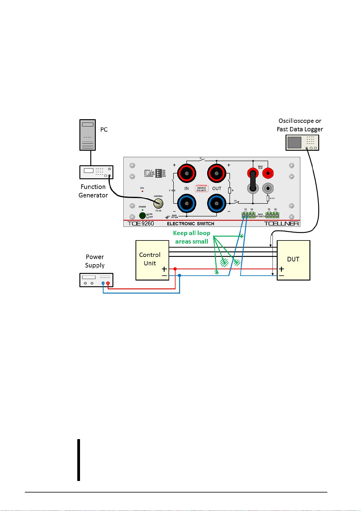
2.3.1 E-13, interruption of signal pins
For the interruption of a signal pin, a signal line switch of the TOE 9260 is used. Such a
signal line switch is applicable for a pin current up to 1 A.
If up to 2 A have to be switched, two signal line switches can be paralleled. It is not
recommended to operate more than two switches in parallel. With three or four switches in
parallel the timing requirements of the LV 124-2013 cannot be fulfilled with a 1 kΩreference
resistor. (For applications different from the LV 124 / LV 148 standards, there are four signal
line switches available in the TOE 9260; if e.g. differential pairs or a 4-pole connection shall
be switched at once.)
Fig. 2 shows the test assembly with use of one of the signal line switches of the TOE 9260.
Only one pin has to be interrupted at one time. The test is then sequentially carried out for
every signal pin of the DUT.
Fig. 2: Test assembly for LV 124, E-13; interruption of a signal pin
TOELLNER Electronic Instrumente GmbH
7
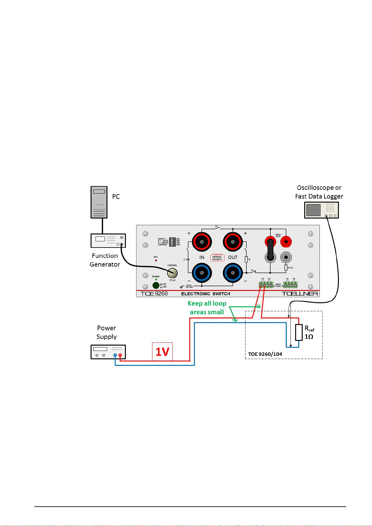
2.3.2 E-13, interruption of signal pins ‒reference measurements
This section applies to LV 124, version 2013 only. That standard requires reference
measurements before an interruption test is carried out with the DUT. Such a reference
measurement gives proof of the slew rate of the switching operation. For the reference
measurements of the E-13 test the DUT is replaced by a reference resistor of 1 Ω± 5 %
resp. 1 kΩ± 5 % of low parasitic inductance.
To avoid the addition of too high cable inductivity, the reference resistor shall be connected
close to the signal line switch by closely spaced wires. The switchable reference resistor
TOE 9260/104 may be connected to power source and signal line switch by provided
suitable cables.
Due to the 1 A current limit of a signal line switch, the measurement with the 1 Ωresistor
shall be carried out at a voltage of 1 V as shown in Fig. 3. Applying such a low voltage level
instead of the actual voltage of the signal pin of the control unit has no significant influence
on the timing of the measured waveform. Reference measurements with the 1 kΩresistor
can be executed with the same voltage as the normal DUT operation voltage.
Fig. 3: Measurement with a 1 Ωreference resistor at a voltage level of 1 V
If the DUT is tested with two paralleled signal line switches (2.3.1), the reference
measurements have to be carried out with the same configuration of paralleled switches.
The test voltage for the 1 Ωreference resistor may be increased up to 2 V.
TOELLNER Electronic Instrumente GmbH
8
2.3.3 E-13, interruption of ground pins
Also for the interruption of a ground pin, a signal line switch of the TOE 9260 is used. Such a
signal line switch is applicable for a ground current up to 1 A.
If up to 2 A have to be switched, two signal line switches can be paralleled. It is not
recommended to operate more than two switches in parallel. With three or four switches in
parallel the timing requirements of the LV 124-2013 cannot be fulfilled with a 1 kΩreference
resistor.
Fig. 4 shows the test assembly with use of one of the signal line switches of the TOE 9260.
Fig. 4: Test assembly for LV 124, E-13; interruption of a ground pin
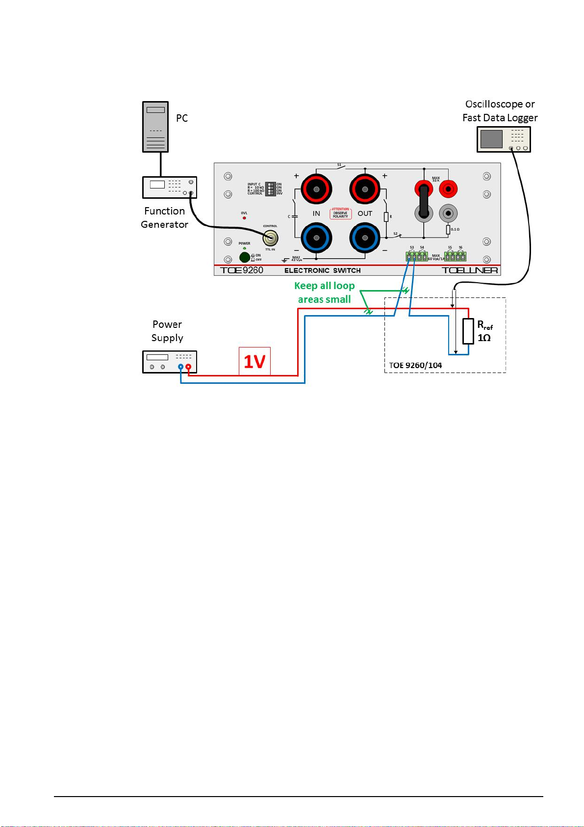
2.3.4 E-13, interruption of ground pins ‒reference measurements
This section applies to LV 124, version 2013 only. That standard requires reference
measurements before an interruption test is carried out with the DUT. Such a reference
measurement gives proof of the slew rate of the switching operation. For the reference
measurements of the E-13 test the DUT is replaced by a reference resistor of 1 Ω± 5 %
resp. 1 kΩ± 5 % of low parasitic inductance.
To avoid the addition of too high cable inductivity, the reference resistor shall be connected
close to the signal line switch by closely spaced wires. The switchable reference resistor
TOE 9260/104 may be connected to power source and signal line switch by provided
suitable cables.
Due to the 1 A current limit of a signal line switch, the measurement with the 1 Ωresistor
shall be carried out at a voltage of 1 V as shown in Fig. 5. Applying such a low voltage level
instead of the actual voltage of the control unit has no significant influence on the timing of
the measured waveform. Reference measurements with the 1 kΩresistor can be executed
with the same voltage as the normal DUT operation voltage.
Note
If the applied power supply has an internal capacity between its minus terminal and earth,
the oscilloscope resp. data logger must not earth the minus terminal of the reference
resistor. A differential probe or an isolating transformer for supplying the oscilloscope resp.
data logger shall be used in this case. Otherwise a capacity appears across the signal line
switch, and the switching timing is slowed down, especially at small load currents as in
case of the 1 kΩreference resistor.
TOELLNER Electronic Instrumente GmbH
9
Fig. 5: Measurement with a 1 Ωreference resistor at a voltage level of 1 V
If the DUT is tested with two paralleled signal line switches (2.3.3), the reference
measurements have to be carried out with the same configuration of paralleled switches.
The test voltage for the 1 Ωreference resistor may be increased up to 2 V.
TOELLNER Electronic Instrumente GmbH
10
3. Tests according to standard LV 148
3.1 LV 148, E48-09, Short interruptions
Fig. 6 shows the test assembly for test E48-09. The 19 mm connecting plug must be placed
as shown.
Fig. 6: Test assembly for LV 148, E48-09
Note
The important points for test execution in line with the requirements of the standard aim at
the wiring as explained in the following:
•The cross section of the cables must fit to the drawn current. For currents up to 100 A
please use the cables TOE 9260/22 and TOE 9260/23 (length 0.50 m) resp.
TOE 9260/24 and TOE 9260/25 (length 1.20 m).
•The two wires from the power supply to the IN sockets of the TOE 9260 have to be laid
as closely spaced as possible (e.g. twisted) to reach minimum inductance values.
•As long as no artificial network is applied between the power supply and the IN sockets of
the TOE 9260, the internal capacitor at the input of the TOE 9260 should be activated by
setting the DIP switch “INPUT C” to “ON”. So the shortest possible rise and fall times of
the voltage at the DUT are achieved.
•If an artificial network between the power supply and the IN sockets of the TOE 9260 is
necessary, the internal capacitor at the input of the TOE 9260 must be deactivated by
setting the DIP switch “INPUT C” to “OFF”. In that case the two wires from the artificial
network to the IN sockets of the TOE 9260 have to be laid as closely spaced as possible
(e.g. twisted) and also kept as short as possible to get short rise and fall times at the
DUT.
•Also the two wires from the OUT sockets of the TOE 9260 to the DUT have to be laid as
closely spaced as possible (e.g. twisted). Any additional cable inductance will act as an
inductive filter together with the resistance and / or capacitance of the DUT, which results
in increased rise and fall times measured at the DUT.
•If the DUT has to be connected by a wiring harness or if a wiring harness is part of the
DUT, the said remarks are valid for the cables from the OUT sockets of the TOE 9260 to
the start point of the wiring harness.
This manual suits for next models
4
Table of contents
Other TOELLNER Switch manuals

Popular Switch manuals by other brands


Lutron Electronics
Lutron Electronics RadioRA 2 Integration guide

CTC Union
CTC Union SB142 product manual

Lightwave Communications
Lightwave Communications USB-Wizard Installation & user guide

LEGRAND
LEGRAND Valena Life manual

Guntermann & Drunck
Guntermann & Drunck DVIMUX4-USB Installation and operations

Tripp Lite
Tripp Lite B004-DPUA2-K owner's manual


