Tohken TFIR-31DM Series User manual

TFIR-31DMSeries
Compact Fixed Mount Image Reader
(Linear / 2D Scanner)
OPERATION MANUAL
TOHKEN CO.,LTD.
2nd Edition
December 8, 2009

[Memorandum]

--
I
Introduction
Thank you for purchasing this product.
This manual explains the features of this product, operation, system configuration,
specifications, etc.
In order to use the product properly, please read this manual carefully.
When there is any problem during normal use, please document it carefully to be
reproduced by our support team.
The contents of this manual may be changed without a notice. Please check our website
for regular updates
Safety Notice
Please do not disassemble this product as this will void the warranty and might
cause an accident.
Please follow the warnings or notices of computers to be used with this
product.
Please stop using the product when there is smoke smell or strange sound to
avoid fire.
DO NOT
DISASSENBLE
Reading
PULL OFF

--
II
CAUTION
Please do not use AC adapters other than the recommend AC power adaptor which is
described in the “unpacking the carton” section. Failure to do so might affect the
performance of the unit.
If the voltage or polarity used is different from the specification, it might cause product
failure and could be the cause of an accident.
Handling with care
CAUTION
About backup data
This product has a memory backup function. This backup can not guaranteed if repair,
reconstruction, and upgrade are performed on this Image Reader.
CAUTION
Please do not use this product at temperature or humidity ranges that are different from
the product specifications or under the direct sunshine.
CAUTION
This unit can be damaged in environment with corrosive gas.
CAUTION
Please do not drip water, moisture, oil, etc. on the unit.

--
III
CAUTION
When stain or dust is stuck on the reading window, please follow the following steps to
clean it:
- Wipe off stain lightly with cloth or swab (wet with alcohol)
- Wipe off again with the dry clothes.
DON NOT Wipe off with any chemicals.
CAUTION
This is a high-precision optical device. Avoid shocking the product such as fall.
Unpacking the product
After you open the shipping package containing the TFIR-31DM, take the following steps:
1- Check for damage that might occur during the shipping process. Report the damage
immediately to the carrier who delivered the shipment.
2- Save the shipping container for later storage or shipping.
3- Make sure everything ordered is present.
Items included with the product
•AC Power Adaptor (Optional)
In case of purchase separately, select an adapter with output DC5V +/- 5% and more than
7W. Please confirm polarity and DC plug type as below.
Polarity:
DC plug type: EIAJ RC5320A Voltage Segment 2
Items included with the product Quantity
TFIR-31DM 1 unit
Operation Manual 1 copy

--
a
TABLE OF CONTENTS
INTRODUCTION.......................................................................................................................... I
SAFETY NOTICE ......................................................................................................................... I
HANDLING WITH CARE ...........................................................................................................II
UNPACKING THE PRODUCT................................................................................................. III
1.GETTING STARTED .................................................................................................................1
1.1 SUPPORTED BARCODES ........................................................................................................2
1.2 PICTURE TAKING ..................................................................................................................2
1.3 ORDERING INFORMATION.....................................................................................................3
1.4 HOW IT WORKS .....................................................................................................................4
2. OPERATION..............................................................................................................................5
2.1 BASIC OPERATION................................................................................................................5
2.2 READING OPERATION...........................................................................................................7
2.3 TRANSMITTING IMAGE DATA ...............................................................................................8
2.4 SWING MODE .......................................................................................................................8
2.5 USB INTERFACE ..................................................................................................................8
3. DESCRIPTION OF READING OPERATION.........................................................................9
3.1 NORMAL MODE ....................................................................................................................9
3.2 READ TIME OUT MODE ......................................................................................................12
3.3 EXTERNAL SYNC MODE.....................................................................................................15
3.4 CONTINUOUS READING MODE ...........................................................................................17
3.5 TEST MODE ........................................................................................................................17
3.6 SWING MODE .....................................................................................................................18
3.7 PRESET MODE....................................................................................................................19
1)Preset Mode 1................................................................................................................19
2)Preset Mode 2................................................................................................................19
3)Output the Preset status..............................................................................................21
3.8 DESCRIPTION OF DIAGNOSIS MODE....................................................................................22
1) Confirmation for Output of Reading statistics and Decoding Time ...........................22
2) Output decode time ........................................................................................................22
3) Output of total decoding time........................................................................................23
4) Symbol Code character System.....................................................................................23
5) Contrast Information .....................................................................................................24
6) Quality Information .......................................................................................................24
7) Output the coordinate of the symbol.............................................................................25
3.9 AUTO DETECTION MODE.....................................................................................................28
3.9.1 Overview ....................................................................................................................28
3.9.2 How to use..................................................................................................................29

--
b
3.9.3 Serial Command ........................................................................................................30
3.9.4 Flow chart ..................................................................................................................32
4. SERIAL COMMAND...............................................................................................................33
4.1 TRANSMISSION SETTINGS ..................................................................................................33
4.2 READING SYMBOLS ............................................................................................................35
4.3 READING OPERATION (NORMAL OPERATION,ADJUSTMENT,DIAGNOSIS) .........................42
4.4 CAMERA CONTROL .............................................................................................................44
4.5 PRESET MODE SETTING .....................................................................................................45
4.6 REFERENCE SETTINGS .......................................................................................................45
4.7 SETTINGS FOR IMAGE OUTPUT ...........................................................................................46
4.8 IMAGE PREPROCESSING .....................................................................................................46
4.9 TABLE OF CHARACTER CODE ..............................................................................................48
5.SPECIFICATIONS...................................................................................................................49
5.1 GENERAL SPECIFICATIONS.................................................................................................49
5.2. FIELD OF VIEW AND HOW TO PLACE THE UNIT ..................................................................51
5.3 DIMENSIONS ......................................................................................................................52
5.3.1 F type (Front View)...............................................................................................52
5.3.2 F type (Front View)...............................................................................................53
5.5 INTERFACE .........................................................................................................................54
6. AUTOMATIC SETUP MODE.................................................................................................58
6.1 OVERVIEW..........................................................................................................................58
6.2 THE PROCEDURE OF AUTOMATIC CONFIGURATION ............................................................59
7.TROUBLESHOOTING ............................................................................................................61
7.1 THE UNIT DOES NOT WORK WHILE PUSHING THE READ TRIGGER SWITCH..........................61
Is power supply voltage within specification? ..................................................................61
Is power supply polarity correct?.......................................................................................61
Is the power rating of the power supply enough?.............................................................61
Is the format of serial command correct?..........................................................................61
Others..................................................................................................................................61
7.2 BARCODE CANNOT BE READ. .............................................................................................61
Is a code setup correct? ......................................................................................................61
Is reading distance suitable? .............................................................................................61
Is the surface of the code glossy?.......................................................................................61
Is the reading window clean? ............................................................................................62
Is the print quality of the code good? ................................................................................62
7.3 THE DATA DOES NOT TRANSMIT OR THE DATA ITSELF IS CORRUPTED. ...............................63
Is the setup with host computer correct?..........................................................................63
Do you set fixed digit for ITF.............................................................................................63

--
1
1.Getting started
The TFIR-31DM is a compact high performance two-dimensional scanner that can read all
traditional 1D and 2D symbologies. Thanks to the special illumination, TFIR-31DM is
suitable for Direct Parts Marking application like laser marking on PCB and metal surface.
Leading the industry in cost-effectiveness, imaging performance and low power consumption,
the TFIR-31DM provides OEMs and Machine building companies with 1D & 2D barcode
scanning capability
The safe, high power LED-based illumination removes the risks involved with lasers without
sacrificing performance. The leading edge field of view provides end-users with freedom from
critical alignment which increases productivity.
. The TFIR-31DM is available in either serial or USB 1.1 interface. The TFIR-31DM has
RS-232C interface to connect to the host computer. The TFIR-31DMU has USB interface to
connect to a host computer that runs Windows2000/XP.

--
2
1.1 Supported barcodes
The unit can read the following symbols:
1D bar codes:
Code39
Code128
Codabar
ITF (interleaved 2 of 5)
JAN/EAN/UPC
RSS
Code93
2D codes:
Data Matrix (ECC200)
QR Code
Micro QR
PDF 417
Micro PDF
Mxi Code
Composite
1.2 Picture taking
The TFIR-31DM can take 24bit color and Grey scale pictures for example signature capture.

--
3
1.3 Ordering information
TFIR-31DM U F - X
1. Model name
2. Interface
If “U” follows “TFIR-31DM” , the scanner has USB interface.
And if there is no “U”, its interface is RS232C.
3. “F” or “S”
These are the position of the reading window. “F” means FRONT and “S” means
SIDE. “F” or “S”
4. Options
Cable modification etc.
According to this rule, there are 4 types of TFIR-31DM family.
・ TFIR-31DM-F
・ TFIR-31DM-S
・ TFIR-31DMU-F
・ TFIR-31DMU-S
1 2 3 4

--
4
1.4 How it works
•Status LED
The status LED lights up either GREEN or RED depending on the operation:
- GREEN light indicates the completion of successful decoding of a symbol.
- Flashing GREEN light indicates the image data transmission in progress.
- RED light indicates the failure of decoding.
•Triggering Switch
This switch is used to initiate the read and decode of a symbol.
•Connecting Cable
- TFIR-31DM: RS-232C
When connecting to a host computer, a cable with D-sub 9Pins connector should be
utilized.
For supplying the power to the unit, the AC power adapter should be plugged into its
mating receptacle on the RS232 connector housing next to the D-sub 9Pins connector.
- TFIR-31DMU: USB
The unit is supplied its power through USB cable via host computer.

--
5
2. Operation
2.1 Basic Operation
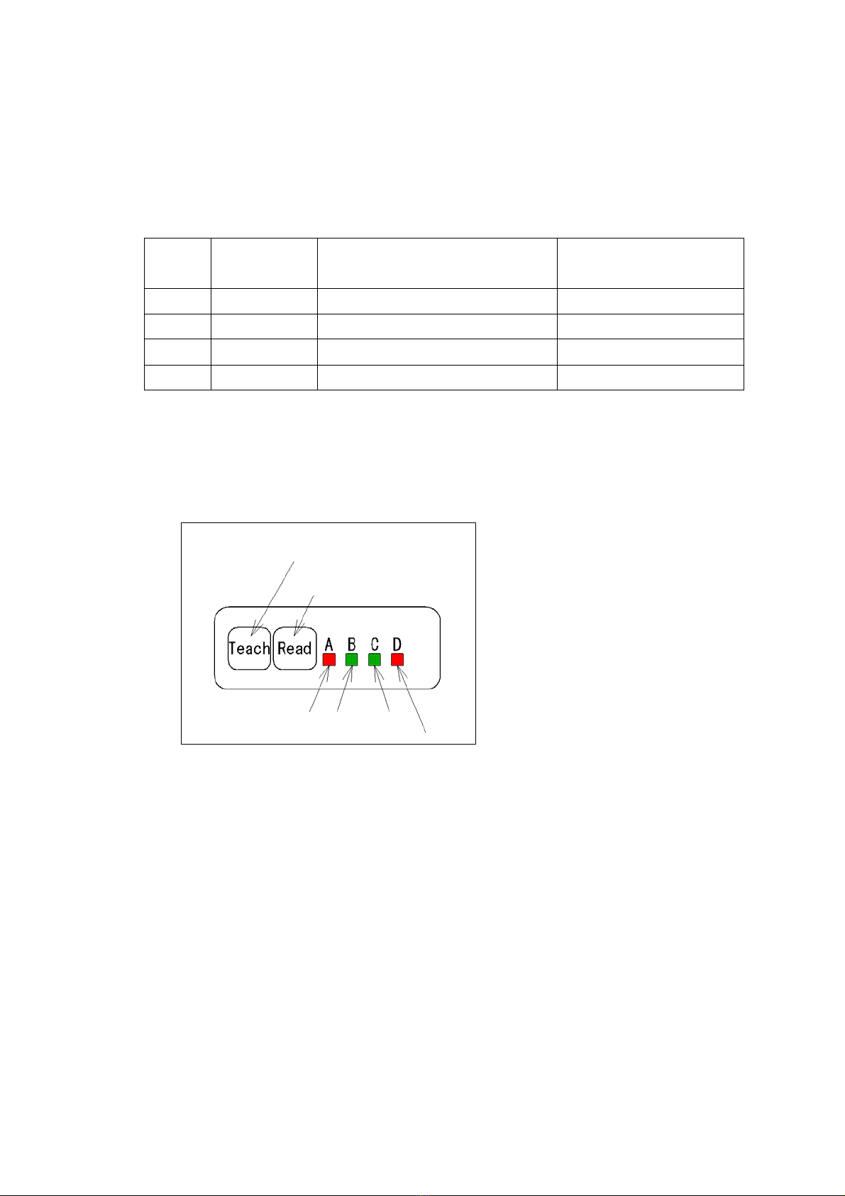
(1) When the power is turned on, LED A, B, C and D turn on simultaneously. After all of them turn
off, only LED B start blinking.
(2) Then two aiming beam indicate where the unit is seeing, where is the center of field of view.
(3) When SYNC is on, the TFIR captures an image and starts decoding the symbol.
The input SYNC can be done through:
- Soft trigger (serial command)
- “Read” button
- SYNC signal input
(4) After successful reading, decoded data is sent by serial interface.
(5) After failing to read:
* The buzzer remains silent.
* Error signal is sent by serial interface.
(6) Back to step (2)
--
6
The following are the functions of four LED indicators
LED
Start up of the
unit Under the normal operation In the setup mode
A (red) ON for 1 second ON with DOUT command Please see section 11
B (green) Always blinking Always blinking (indicating “Ready”) Please see section 11
C (green) ON for 1 second ON while data is sent through RS232 Please see section 11
D (red) ON for 1 second ON while data is received through RS232 Please see section 11
LED indicator C and D are used for monitoring RS232C connection. But these do not indicate RSCS
confirmation signals are being sent.
Appearance of the buttons and LED indicators
Teach button
Read button
RED RED
GREE GREE

--
7
2.2 Reading Operation
The unit has various types of mode operations.
Reading operation means capture image and decode the symbol.
Operation Mode Command Function
Normal Mode SYNCMODE=0 Single SYNC input performs single decode.
Reading Time out Mode SYNCMODE=1 After trigger input, it starts setting interval time
duration setting command TOTALLIM=.
External SYNC Mode SYNCMODE=2 Read operation is continued while SYNC
signal from the input is on.
Continue Reading Mode continue
Sending continuous read command
“continue” to the unit starts read until
termination command received.
Test Mode TEST=1 It measures the read rate.
To stop operation, send command TEST=0.
For more details, please refer at Chapter 3.

--
8
2.3 Transmitting Image Data
Bitmap/image (name*.bmp, 1280 x 1024 pixel)
•Transmitting the data with serial interface takes about 160 seconds with baud rate
15.2Kbps (TFIR-31DM
•In case of USB1.1, (TFIR-31DMU), transmitting the data takes approximately 10
seconds
Notes:
The image size is changeable.
2.4 Swing Mode
Swing mode is used to setup the shutter or gain value.
2.5 USB Interface
•Please confirm that the USB port of the host PC is available.
•Plug into the USB port when the host PC is running.
•Please install the USB driver. This operation is needed only when the device is used
for the first time.
•Please confirm the communication between the TfIR and the host is successful by
using communication software such as hyperterminal or USBTerm (USBTerm can be
downloaded from our secure website).
•After device driver is installed, a computer looks at USB port as virtual com port.
•The unit and computer transceiver data is using same communication protocol. It is
necessary that the following functions are provided in software.
-The function for transmitting a serial command that’s required for setup
-The function for receiving the barcode data from this unit
Note: The driver can be downloaded from our secure web site.
URL: http://www.tohken.co.jp/

--
9
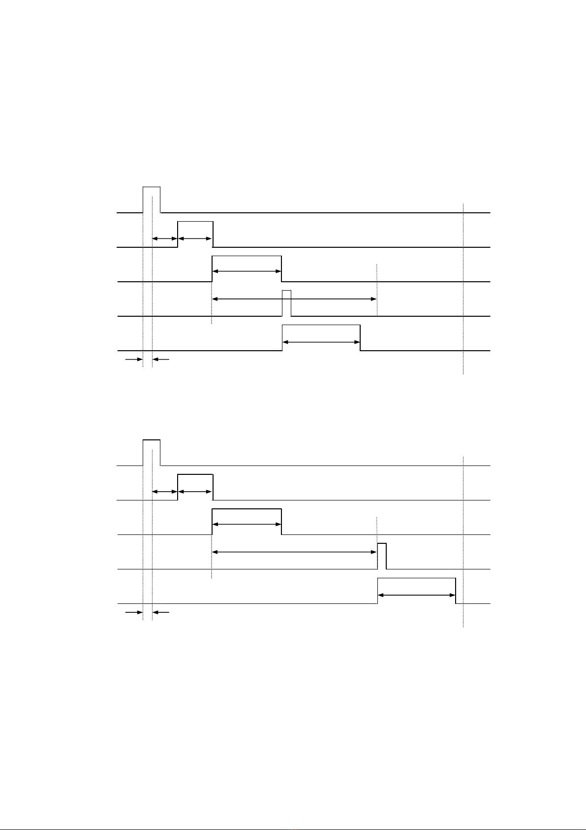
3. Description of reading operation
DELAY::The time from getting SYNC ON to reading
CHATT: The time for eliminating the chattering
IMAGE: The time for capturing an image
DECODE: The decoding time
DECODELIM: The maximum time for decoding
GOOUT: The time for outputting GO signal
NGOUT: The time for outputting NG signal
SERIAL: The time for outputting data through serial interface
3.1 Normal Mode
The SYNC input is turned ON by the single soft trigger (read start signal) then capture single
image and it decodes.
DELA
Y
SYNC
IMAGE
DECODE
SERIAL
GO-OUT
GOOU
T
DECODELIM
decode
1
image1
Fig. 3.1-1 Soft Triggert Trigge, Read OK, Data Transmit; After decoding
--
10
DELA
Y
SYNC
IMAGE
DECODE
SERIAL
NG-OUT
NGOU
T
CHAT
T
DECODELIM
decode
1
image
1
Fig. 3.1-3 Hard Trigger, Read NG, Data Transmit timing ; After decoding
DELA
Y
SYNC
IMAGE
DECODE
SERIAL
GO-OUT
GOOU
T
CHAT
T
DECODELIM
decode
1
image
1
Fig. 3.1-2 Hard Trigger, Read OK, Data Transmit timing; After decoding

--
11
Fig. 3.1-4 Hard Trigger, Read NG, Data Transmit timing; Judged as NG
DELA
Y
SYNC
IMAGE
DECODE
SERIAL
NG-OUT
NGOU
T
CHAT
T
DECODELI
M
decode1
image
1

--
12
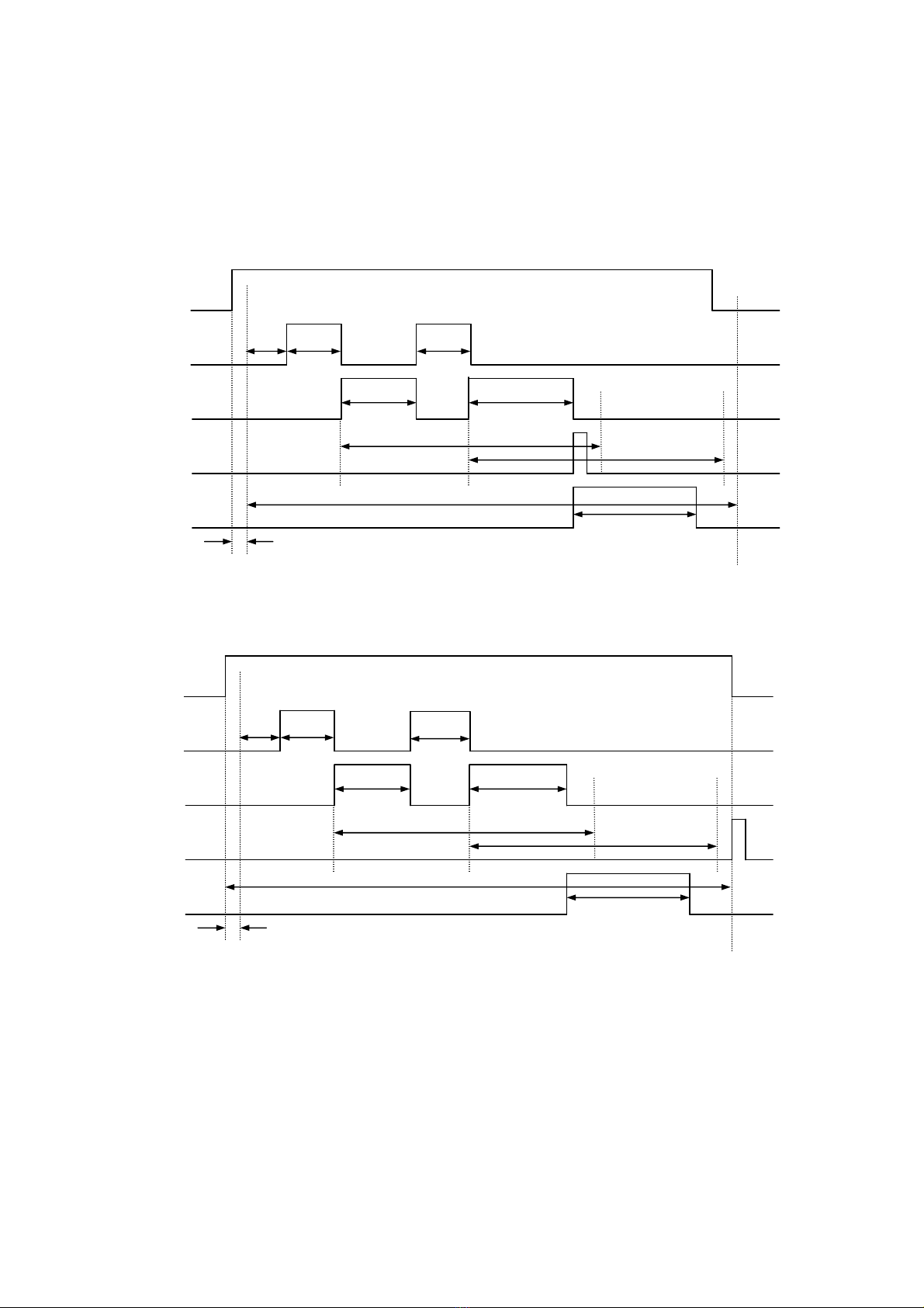
3.2 Read Time Out Mode
After trigger input, the unit starts the timer for setting interval duration (setting command
TOTALLIM=). When the reading operation is failed, an error code transmits after the end of the
reading time set up by TOTALLIM.
SYNC
IMAGE
DECODE
SERIAL
OUT
GOOU
T
DECODELIM
DECODELIM
decode
1
decode2
image
1
TOTALLIM
image2
Fig. 3.2-1 Soft Trigger, Read OK, Data Transmit: After decoding, Judge
Output: with reading result output
DELA
Y
SYNC
IMAGE
DECODE
SERIAL
OUT
GOOUT
DECODELIM
DECODELIM
decode
1
decode
2
image
1
image
2
TOTALLIM
Fig. 3.2-2 Soft Trigger, Read OK, Data Transmit: After Sync OFF, Judge Output: with
r
ead
in
g
r
esu
l
t
output
--
13
Fig. 3.2-3 Hard Trigger, Read OK, Data Transmit: After decoding, Judge Output: right afte
r
decoding
DELA
Y
SYNC
IMAGE
DECODE
SERIAL
OUT
GOOU
T
CHAT
T
DECODELIM
DECODELIM
decode
1
decode
2
image
1
image
2
TOTALLIM
DELA
Y
SYN
C
IMAG
E
DECOD
E
SERIA
L
OUT
GOOU
T
CHAT
T
DECODELIM
DECODELIM
decode
1
decode
2
image
1
TOTALLIM
Fig. 3.2-4 Hard Trigger, Read OK, Data Transmit: After Sync OFF, Judge Output: with reading
result output
image
2
Table of contents
Other Tohken Scanner manuals


