TOIP Pty TBS12 User manual

TBS12 Console
Version 1.05
February 2020
Copyright TOIP Pty Ltd

Table of Contents
1. Introduction................................................................................................4
2. oftware installation...................................................................................5
3. Hardware setup.........................................................................................6
3.1. Connect COM Port............................................................................6
3.1.1. TB 12H (T shaped PCB for Otto MP)....................................6
3.1.2. TB 12 .....................................................................................7
3.1.3. TB 12B.....................................................................................7
3.1.4. TB 12 PC-F ............................................................................8
3.2. Install Batteries..................................................................................8
3.2.1. TB 12B.....................................................................................8
3.2.2. TB 12 .....................................................................................9
3.2.3. TB 12H.....................................................................................9
3.2.4. TB 12 PC-F ............................................................................9
3.3. ensor Connection..........................................................................10
3.3.1. TB 12H...................................................................................10
3.3.2. TB 12B and TB 12 ..............................................................10
3.3.3. TB 12PC-F ...........................................................................10
4. Connecting to the TB 12.........................................................................12
4.1. Operation Mode...............................................................................13
5. TB 12 Configuration equence..............................................................15
5.1. Board Information............................................................................16
5.2. Time ettings...................................................................................17
5.3. chedule ettings............................................................................17
5.4. LoRa Module ettings.....................................................................18
5.4.1. LoRa RF..................................................................................18
5.5. ensor Configuration.......................................................................19
5.5.1. TB 12 - DI Commands.........................................................19
5.5.2. TB 12PC Pulse Inputs............................................................20
5.5.3. TB 12F Float witch Inputs.................................................21
5.6. ave Config for This Device............................................................23
5.7. Writing a Configuration to the TB 12..............................................23
5.8. Using the Direct Command Mode...................................................24
5.8.1. LoRa WAN Commands...........................................................24
5.8.2. DI-12 ensor Testing...........................................................26

5.9. Checking Firmware Revision...........................................................26
1.1. tarting the Unit Logging.................................................................28
6. Other Functions.......................................................................................29
6.1. View Options....................................................................................29
6.1.1. Clearing the Log......................................................................29
6.1.2. Displaying the Time/Date of events.........................................29
6.1.3. Displaying Log Events.............................................................29
6.2. Reading ettings from TB 12.........................................................29
6.2.1. Displaying the Battery Voltage................................................29
6.2.2. Viewing the Device ID.............................................................30
6.2.3. Viewing the Firmware Version.................................................30
6.2.4. Reading the Date-Time...........................................................30
6.2.5. Reading the LoRa ettings.....................................................30
6.2.6. Reading the ensor ettings..................................................30
6.2.7. Reading the chedule ettings...............................................30
7. TB 12 Data format..................................................................................31
7.1. Battery data format..........................................................................31
7.2. ensor data format..........................................................................31
7.2.1. TB 12 , TB 12B, TB 12 M.................................................31
7.2.2. TB 12PC-F Pulse Count Mode............................................32
7.2.3. TB 12PC-F Flow witch Mode............................................33
8. Backend etup........................................................................................34
8.1. Configuration Requirements............................................................36
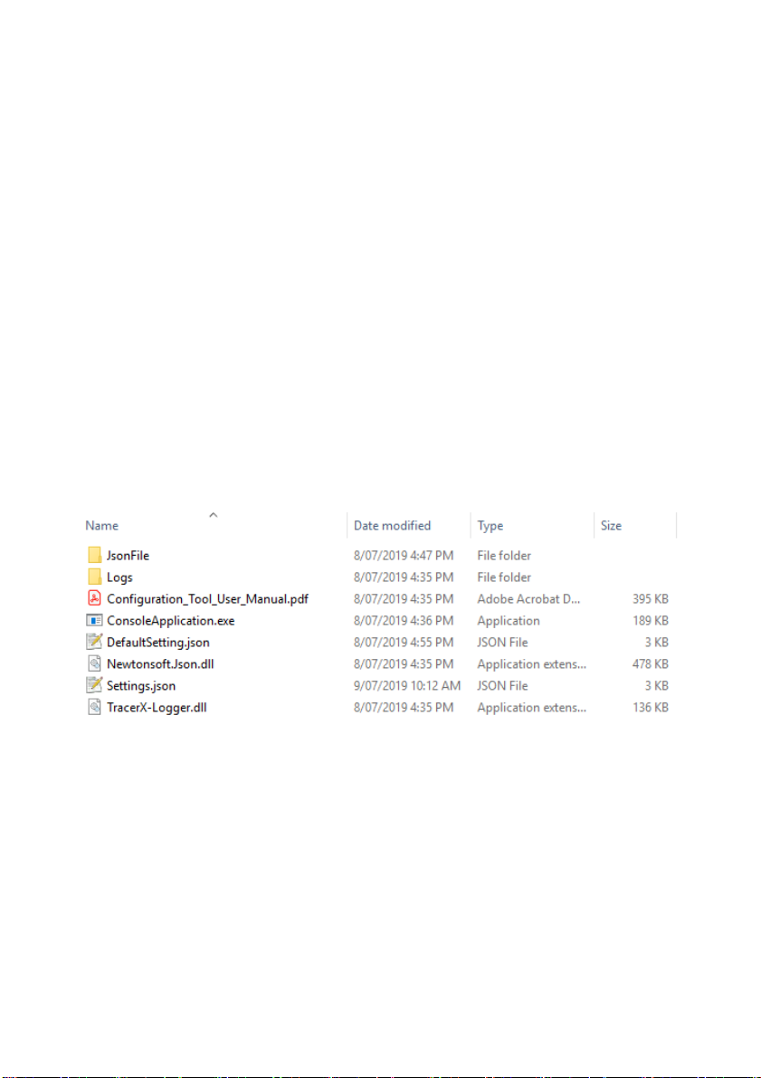
9. TB 12 Console Log Files........................................................................38
10. TB 12 Firmware Upgrade.....................................................................39
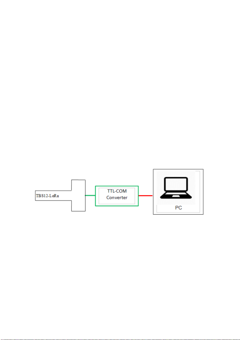
10.1. Equipment Required......................................................................39
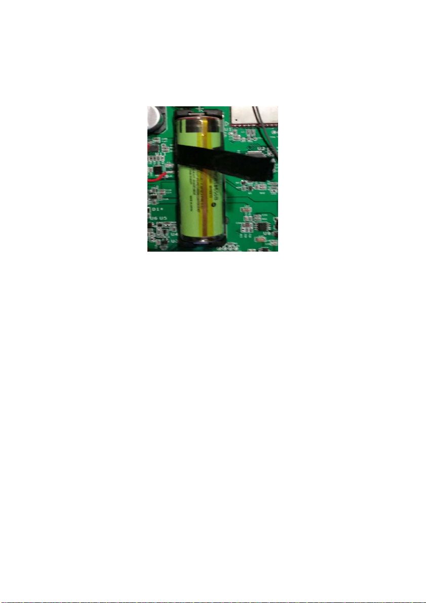
10.2. Preparation....................................................................................40
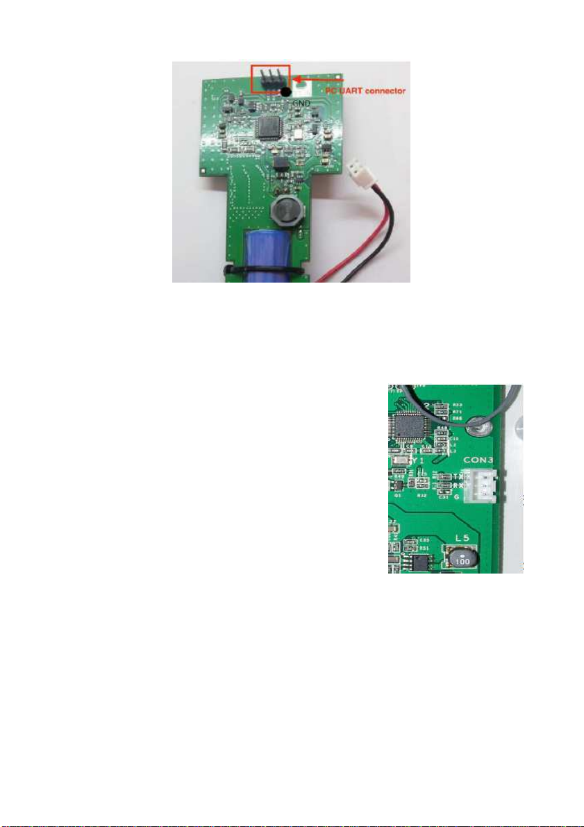
10.2.1. TB 12B, TB 12 , TB 12PC................................................40
10.2.2. TB 12PC/F .........................................................................41
10.3. Firmware Update...........................................................................41
11. Rising HF Modem Firmware Upgrade...................................................43
11.1. Preparation....................................................................................43
11.1.1. TB 12B & TB 12 ................................................................44
11.1.2. TB 12PC/F .........................................................................44
11.2. Upgrade Process...........................................................................45

1. Introduction
The DI12-LoRa Console is used to program the various versions of the
TB 12, DI-12 to LoRaWAN Bridge which are manufactured by Tekbox.
These include:
TB 12H Head for Otto oil Moisture Probe (Otto-LO)
TB 12B Enclosure mounted unit with dry cell batteries
TB 12 Enclosure mounted solar powered unit with
rechargeable battery
TB 12PC dual input pulse counter
TB 12F dual input flow switch (alarm)
TB 12T LoRa WAN Temperature Tracker
The TB 12 must be connected to a computer via a U B to FTDI adaptor.
Once connected the Console can be used to set all the board’s operational
parameters (time settings, DI-12 commands, LoRaWan settings) and
send commands to DI-12 sensors or the LoRaWAN module on the board
and to display the received responses.
This manual is written around version 1.04 of the TB 12 firmware and
Console program.

2. Software installation
To avoid issues with permissions, copy the Console application files to the
“AppData/Local/Programs” directory for the current user:
C:/<user name>/AppData/Local/Programs/TB 12
After creating the folder and copying the files, make a new desktop
shortcut, linked to the file “ConsoleApplication.exe”.
The TB 12 Console is written in the C# (C harp) programming language
and utilises the Microsoft “.NET Framework 4”. This is supplied with the
package (Newtonsoft.json.dll).
The application consists of 4 files plus an optional default file. During
operation, it will automatically create a “Logs” directory to store logging
information and errors.
Configuration files should be stored in the JsonFile directory.

3. Hardware setup
To ensure that the TB 12 connects to the Console without you having to
wait a full log cycle, connect the COM port prior to fitting the battery.
3.1. Connect COM Port
To keep the TB 12 design simple and to minimise power consumption, the
serial interface on the unit utilises “TTL” signal levels. A level conversion
circuit is thus needed to translate these signals to the U B format used on
a PC. These may be called a U B to FTDI converter or U B to TTL
converter.
All TB 12 variants provide a 3 pin J T socket for the communications /
programming port.
Please ensure that your TB 12 unit has been supplied with the correct
adaptor. If you are not sure, contact TOIP or your distributor. Most U B to
FTDI adaptors utilise the FTDI driver which can be downloaded from:
http://www.ftdichip.com/Drivers/VCP.htm
3.1.1. TBS12H (T shaped PCB for tto SMP)
Current TB 12 M boards have a J T socket fitted. If you have an old
board with the 3 pin header, you will need an adaptor cable.
If you hold the PCB so that the pins on the header are facing you, the pin
on the right is the ground pin.
The 3 pin header is not polarised: When you connect the plug from the
U B Adaptor make sure it is lined up so the black mark is on the side with
the dot on the PCB.

3.1.2. TBS12S
To open the TB 12 , turn the unit upside down and remove the 6 screws
holding the cover to the base. lowly turn the unit back over and collect the
screws as they fall out.
Now remove the cover
the cover is connected to the TB 12 PCB
via the solar panel cable
to remove the cover completely, unplug the 2
pin header (CON2)
The TB 12 PCB is fitted with a 3 pin J T header
which is labelled CON3. If the unit is held with the
antenna on top, the connector is 2/3 the way down
the PCB on the right side.
The J T plug is polarised so it will only go in one way. Plug the header from
your adaptor cable in to this socket and open the Console.
3.1.3. TBS12B
To access the programming port, undo the 4 Philips head screws holding
the lid in place, then lift the cover off.
The TB 12 PCB is fitted with a 3 pin J T header which is labelled CON3.
If the unit is held with the antenna on top, the connector is just below the
bottom left corner of the battery holder.

The J T plug is polarised so it will only go in one way. Plug the header from
your adaptor cable in to this socket and open the Console.
3.1.4. TBS12 PC-FS
The TB 12PC/F is fitted with a 3 pin J T header which is labelled CON 4.
This connector is located on the lower left of the PCB.
3.2. Install Batteries
3.2.1. TBS12B
The TB 12B is powered by a set of 2 off 1.5Volt alkaline D cells. Please
ensure you use high quality cells (Energizer, Duracell) in order to obtain
maximum battery life.
When inserting the cells into the holder, take care to align them according
to the polarities shown on the holder.

3.2.2. TBS12S
The TB 12 battery is a type 18650 rechargeable Lithium Ion cell with a
nominal voltage of 3.7V. It sits in a holder in the centre of the PCB.
To make it easier to remove the battery, a Puller can be made up using a
piece of ribbon: cut an 80mm length of 8 to 12mm wide ribbon. Fold in half
and glue the last 20mm of each end together with superglue. Once the glue
is dry, you can sleeve the ribbon over the battery. The end of the ribbon can
then be used to lift the battery out of the holder.
3.2.3. TBS12H
The battery for the TB 12H is fitted in to the slot cut into the PCB and
secured with a zip tie. Plug the battery cable in to the matching socket on
the PCB.
3.2.4. TBS12 PC-FS
The TB 12PC/F may be powered using the on board batteries or an
external supply
if using the on board batteries, load 2 off Alkaline AA cells in to the
holder
if using an external supply (3.6V lithium cell or regulated 3.3V DC
power supply) connect the supply to CON 6 on the top left of the
PCB.
CAUTION: The Battery plug on the TB 12 M head for the Otto soil probe
is wired reverse to that on the TB 12PC-F . Please check the wiring
before using any pre-wired batteries with these devices.

3.3. Sensor Connection
With the exception of the TB 12H, the sensors connect via an M14 socket.
3.3.1. TBS12H
The TB 12H (T-Head) connects to the Otto soil moisture sensors via 5 Pin
J T connectors. For testing you should ensure that at least one sensor (on
address 0) is connected.
3.3.2. TBS12B and TBS12S
The TB 12B and TB 12 connect to the DI-12 sensors via a 7 pin
waterproof M14 connector. The socket, which is on the bottom of the
enclosure, is wired as follows:
This image is taken looking at the socket on the TB 12 body face on. If you
plug the 7 pin plug into the socket and stand the unit on its head so the
connector is on top, the orientation will be the same when you look down
on the back of the plug from above (after taking off the backshell)
You can test connectivity to and functionality of, the sensors using the
Direct Command mode (Refer section 5.8.2 ).
3.3.3. TBS12PC-FS
The TB 12 PC-F is used with switches which provide a closed contact
when they are active. These may be reed switches fitted to a rain gauge or
flow meter, or switches fitted to an alarm contact or float switch. In all
cases, the switch must make two contacts available: a Common (which is
wired to the ground terminal on the inputs) and the witch input. When the

switch operates (i.e. the contacts close, the input line is connected to the
ground terminal.
With the TB 12PC (pulse count) module, the switch
closes for a brief period (typically 20 m ec). Whereas
with the TB 12F , the switch may be closed for
minutes or hours.
The sensors on the module connect via the two pin
headers labelled CON 2 (input 1) and CON 6 (Input
2). These are located on the upper left side of the
PCB.

4. Connecting to the TBS12
To operate the TB 12 and Console together:
first connect the serial to U B adaptor as shown in ection 3
open the Console by clicking on the desktop shortcut you created
in ection 2
menu functions which send commands to the device will be greyed
out at this stage
those functions that read or write to a configuration file will be
active as will those to connect to the device
the buttons to control communications show the current state i.e.
“COM Closed”. Click on the button to Open the communications
port
◦the label will change to COM Open
from the menu select Settings / COM Port
when the Config Com menu displays, click on the drop down list
box labelled Port Name and
choose the port allocated by
Windows to your FTDI to U B
adaptor
◦if you can’t see the port, click
on the Refresh button
◦if you are still having problems,
open Windows Device
Manager, then check to see if
a new COM port appears as
you plug and unplug the
adaptor. If you do not see the
adaptor, check that the driver
is installed and that Windows
is not blocking the Driver

click on the K button
then, at the Main Console screen, click on the button labelled COM
Closed
◦this opens the connection to the U B-TTL adaptor
◦the log screen should display the text Open Com Port :
Passed
◦click on the Disconnected button to Connect to the TB 12
▪the button label will change to “Connecting” while the
Console attempts to communicate with the TB 12
▪the label will change to Connected once successful.
Connection equence:
the two buttons manage the connection firstly to the U B-TTL
adaptor and secondly to the TB 12
during a normal connection sequence, you will move the unit
through the following states:
C M C NNECTI N
once the Port is Open and the TB 12 connected, the Operation
Mode buttons will be activated
4.1. Operation Mode
The TB 12 has two operating modes:

Console mode: this mode is used when you configure and test the
TB 12. Any changes you make to the configuration and send to
the device will not be activated until it is set to logging mode
Logging mode: when in this mode the TB 12 will automatically
read the attached sensors and transmit the values to the LoRa
erver. In between readings the unit goes in to sleep mode.
Once the TB 12 is in logging mode, it will regularly check to see if a U B-
TTL adaptor is plugged in to the COMM port. If so it will activate the port
and check for commands. The unit should thus respond within 20 or 30
seconds to a change back to Console mode.
If the unit does not respond, remove the battery and restart it:
•The TB 12 units have large storage capacitors on the PCB which
will retain power for a while after the battery is removed. To ensure
the unit restarts:
•connect the U B to TTL converter and Open the Console
•remove the battery
•short the terminals on the battery holder on the PCB for 1
second
•replace the battery and wait for a message on the Console.

5. TBS12 Configuration Sequence
When setting up a new TB 12, you need to perform the following steps:
open the TB 12 Console program
connect the erial to U B Converter to your PC and identify which
COM port it is allocated (via Device Manager)
connect the other end of the U B converter to the TB 12
from the TB 12 Menu select Settings / Com Port and then set the
Port Name to match the port you identified for the converter
◦if the converter was recognised before you start the Console,
the port should show in the drop down list
◦leave the other parameters at the default setting then click on
OK
click on the COM Closed button to connect to the U B-TTL
adaptor: the button label will change to COM Open
apply power to the TB 12 (i.e. plug in the battery connector)
then click on the Disconnected button to connect to the TB 12
◦depending on the settings of the board, it may take a while for
the board to wake
◦If you don’t want to wait, select Com Open again to close the
connection, remove the battery and follow the process shown
earlier to restart the unit
check the peration Mode displayed on the upper right of the
screen
◦if it is showing Logging Mode click on the Console Mode
radio button
◦wait while the unit connects and changes modes
◦a message will display on the console to indicate that the
device has connected.
Note:
It is possible for the Console and TBS12 to get out of step if the
Console thinks the board is in one mode when it is really in the other.
This will be evident as an inability to connect to the TBS12. If this
occurs, try the following:
make sure the Console open and connected,
remove the RTU battery
toggle the Mode setting from Console to Logging or Vice
Versa
replace the RTU battery and allow the unit to re-start
you may need to try this a couple of times to get the two back
in step with one another.

Once the connection to the TB 12 is established, you can create a
configuration file for your device
to start with a default configuration, click on File / Load Default
ettings
if you have an existing file you want to open or to use as the
template for the new device, select File / Load and then
choose the desired file
from the TB 12 Menu select Settings / Boards
the Board configuration screen will display
from the elect Boards list box, choose the TB 12 type you are
working with e.g. TB 12H/B/
you can the progress to setting up the various parameters.
5.1. Board Information
The Board Information area shows you the ID number allocated to the unit
and the firmware version
•Device ID: this is a hexadecimal number used to uniquely identify
the device
◦this can be used to track the location and history of a PCB
◦the Device ID should be set when the device is new and then
remain with the device even if it is moved from one location to
another
•FW Version: this shows the version of the firmware loaded in to the
board. You can also fetch this from the menu using View / Get
Firmware Version
◦the TB 12 firmware version must always match the Console
firmware version.

5.2. ime Settings
All of the LoRa WAN nodes should be operated with the time set to UTC
(Universal Coordinated Time, also often called GMT). This matches with
the settings in the ensori platform and avoids issues with having to
change the time when daylight savings starts and ends (which always
causes an hour data gap). When the data is viewed, a time offset will be
applied according to the time zone set for the location in which the unit is
installed.
To set the time:
from the Boards Configuration screen, click on the Time Zone
tab
from the Time Zone election list box, select UTC – Universal
Coordinated Time
to set the time in the board, click on the Set Time for External
RTC button.
5.3. Schedule Settings
These control how often measurements are made and transmitted.
Normally the Measurement Interval and Transmit Interval will be set to the
same value
Transmit Interval: set this to how often you want the values to be
sent. Normally this is the same as the Measurement Interval e.g.
15 min for soil moisture and weather, 8 hours for groundwater
Measurement Interval: set to 15 or 30 minutes for soil moisture
sensors
◦on the TB 12PC-F the measurement interval must equal the
Transmit Interval
Transmission Delay: adds a delay after the read is completed
before the unit sends its data
◦within the LoRaWAN ecospace, it is assumed that nodes will
wake at random and send values. This approach is fine when
nodes only transmit a few packets once a day
◦But in our applications (with lots of data and frequent
transmission) we need to manage transmissions so that they
don’t all occur at once (collisions)
◦First estimate how long it will take for the node to read the
sensors (e.g. 10 seconds), then allow another 10 second buffer
and start to add your Nodes with a 10 or 20 second offset: first

Node Delay = 30, 2
nd
Node Delay = 40, 3
rd
Node Delay = 50
etc. You may need to maintain a separate list of what Delay
you allocate to each node (if you save each configuration file
you can easily recall the settings at a later time)
Battery Transmission Cycles: to save air time, you can reduce the
rate at which the battery information is sent. For example set this to
every 4 cycles (2 hours for 30 min log, 1 hour for 15 min log)
5.4. LoRa Module Settings
You now need to set up the LoRaWAN parameters to match the network
you are connecting to. This process begins at the level of the LoRaWAN
Application erver. Add each node on the server and record all of the
relevant details, then transfer them to the TB 12 Console:
LoRaWAN Mode: In closed (private) networks, you will normally
use ABP but if you are using a public network, the provider may
stipulate the use of OTAA. The Network settings you need to
program will change depending on whether you are using ABP
(Activation by personalisation) or OTAA (Over the air activation)
◦ABP: uses NWK KEY and AP KEY
◦OTAA: uses APPLICATIONEUI and APPLICATIONKEY
Device Address, Device EUI, Nwk Key, App Key, ApplicationKey:
set to value from LoRaApp erver
◦copy and paste these exactly as they appear in the backend
LoRa erver
ACK Options: there are two approaches to making sure
transmissions get through
◦The simple approach is to send them multiple times (No Ack
from erver). This can waste a lot of air time: if the first packet
is received every time, sending it a 2
nd
or 3
rd
time is a waste of
time and power
◦The more complex (and more robust) approach is to wait for
the server to acknowledge or confirm that it has received each
packet. The Node and Gateway then maintain a Packet
Counter which is incremented each time a packet is sent
◦Acknowledged Packets should be used on al soil moisture and
weather monitoring stations i.e. enable the checkbox labelled
“Wait ACK from server”
5.4.1. LoRa RF
In this area you set up all of the radio parameters to match the country in
which you are operating

ADR: the adaptive data rate option allows nodes closer to a
Gateway to transmit at a higher speed than nodes further away.
This helps maximise the time window available for nodes to
transmit. But the feature is is most benefit in large public networks.
The default should be to set ADR OFF
◦the major limitation of ADR is that it reduces the data rate to
low values when signal strength is poor (i.e. a node is a long
way from the Gateway). But under the LoRa Protocol, the low
data rates do not allow long packets, so those from multi-
sensor soil moisture probes will be blocked. o with these
devices you are limited to data rates of 4 and above
◦so if you are planning on using ADR, make sure that you set
the “DR MIN” to a value of 4 and the DR MAX to a value of 5
PORT: this defines the port used by the modem internally for LoRa
◦it must be set to a value of 8
TX POWER: sets the maximum transmitter power: set to 14
DR: this setting controls the default data rate used when sending
the packets
◦lower data rates will provide longer range but tie up the
network for longer. The default should be to use a DR of 5 and
you can the then try 4 and 3 if you want to get more range
FREQ CHEME: click on the drop down list and choose the AU915
entry, which will set the broad channel plan to match the Australian
915 to 928 MHz scheme
ET CH: now click on the ET CH button to view a list of the
current channel settings
◦The default for Australia is sub-band 1, with the channels set
on 0.2MHz increments from 916.8 to 918.2
◦If the network in your area is congested, you may wish to
choose one of the other sub-bands (this will have to be set in
the Gateway and on each node).
5.5. Sensor Configuration
Providing you have selected the correct Board when you began this
process, the ensor tabs will show the options available for your TB 12:
DI on the TB 12 M/B/ , Pulse for the TB 12PC and Float witch for the
TB 12F .
5.5.1. TBS12 - SDI Commands
In the DI Commands area, you add details of the DI-12 commands used
by the various sensors connected to the TB 12. A separate data packet is
transmitted for each Ordinal or line added to the list.

Add a line for each individual measurement command you will be using.
for an EnviroPro or Otto probe you will use 0C! for the soil moisture
and 0C2! for soil temperature. If you are using an EnviroPro EC,
you add 0C! for the EC
for a 3 sensor “Naked” or Otto LO probe, you will need 3 command
entries in the table: 0C1!, 1C1!, 2C1!
When you have finished adding the settings, click on the AVE
button.
Take note of the order in which you add your sensors as this must be
reproduced in the same format when you add the device in the Tekbox IoT
Broker
•the TB 12 firmware reviews the commands which have been
entered and uses the information to assign the ensori ID and ub
ensor ID
•sensors on the first address (e.g. 0) are sent with ensor ID 0
◦the first measurement command (0C) which is shown as
Ordinal 1 in the example above, will be sent as ub ensor ID
0
◦the 2
nd
command (ordinal 1 in the example) as ub ensor ID 1
•the first sensor on the next address (ordinal 3 in the example) will
be sent as ensor ID 1, ub ensor ID 0.
This information will also help you if you are monitoring the Data Packets
as they are received in the Application erver on TTN / Loriot.
Table of contents