AudioArts Engineering AIR 1 User manual
TECHNICAL MANUAL
December 2007
AIR 1
R
ADIO
M
IXING
C
ONSOLE

R-16 / Dec 1997
AIR 1 Radio Mixing Console Technical Manual - 1st EditionAIR 1 Radio Mixing Console Technical Manual - 1st Edition
AIR 1 Radio Mixing Console Technical Manual - 1st EditionAIR 1 Radio Mixing Console Technical Manual - 1st Edition
AIR 1 Radio Mixing Console Technical Manual - 1st Edition
©2007 Audioarts®Engineering*
AUDIOARTS ENGINEERING
600 Industrial Drive
New Bern, North Carolina 28562
252-638-7000
*a division of Wheatstone Corporation
AIR 1/ Dec 2007

page Contents – 1
AIR 1 / Dec 2007
CONTENTS
AIR 1 Technical Manual
Table of Contents
Chapter 1 – Installation and Power
Unpacking and Installing the Console ........................................1-2
Power Supply ................................................................................1-3
Energizing......................................................................................1-3
Audio and Control Wiring.............................................................1-4
Unbalanced Connections (analog audio) ................................................................. 1-5
Hook-Ups .......................................................................................1-5
MIC 1 and MIC 2 Inputs............................................................................................ 1-5
LINE 3 IN through LINE 8 IN .................................................................................... 1-5
EXT IN ...................................................................................................................... 1-6
PGM 1 OUT and PGM 2 OUT .................................................................................. 1-6
MONITOR OUT ........................................................................................................ 1-6
CUE .......................................................................................................................... 1-6
HDPN........................................................................................................................ 1-6
TALLY ....................................................................................................................... 1-7
SPARE...................................................................................................................... 1-7
Chapter 2 - Console Features
Overview ........................................................................................2-2
Inputs .............................................................................................2-4
Analog Mono Mic Level Inputs ................................................................................. 2-4
Analog Stereo Line Level Inputs .............................................................................. 2-4
Outputs ..........................................................................................2-5
Program Outputs ...................................................................................................... 2-5
Monitor Output .......................................................................................................... 2-5
Cue to Monitor ..................................................................................................... 2-5
Split Cue, Monitor ................................................................................................ 2-6
Split Cue, Headphone ......................................................................................... 2-6
Monitor Mute........................................................................................................ 2-6
On Air Tally .......................................................................................................... 2-7

page Contents – 2
AIR 1 / Dec 2007
CONTENTS
Chapter 3 - Controls and Functions
Input Section .............................................................................. 3-2
Source..................................................................................................................... 3-3
Program Assign ...................................................................................................... 3-3
Cue Button .............................................................................................................. 3-3
Fader....................................................................................................................... 3-3
ON Button ............................................................................................................... 3-3
Master Section............................................................................ 3-4
Monitor .................................................................................................................... 3-5
Program Select .................................................................................................. 3-5
EXT Switch ........................................................................................................ 3-5
Monitor Fader .................................................................................................... 3-5
Cue Level Control.............................................................................................. 3-6
Headphone Fader.............................................................................................. 3-6
Meters ..................................................................................................................... 3-6
VU Meter Pair .................................................................................................... 3-6
Meter Select Buttons ......................................................................................... 3-7
On Air LED.............................................................................................................. 3-7
Chapter 4 - Schematic and Load Sheet Drawings
Console Flow Diagram .............................................................. 4-2
MBA1-1 Mother Board
Schematic ............................................................................................................... 4-3
Load Sheet............................................................................................................ 4-11
VUA1-2 Meters PCB
Schematic ............................................................................................................. 4-12
Load Sheet............................................................................................................ 4-13
Appendices
Appendix 1
AIR 1 Console Performance Specifications ............................A-3
Appendix 2
Replacement Parts List .............................................................A-5

INSTALLATION and POWER
page 1 – 1
AIR 1 / Dec 2007
Installation and Power
Chapter Contents
Unpacking and Installing the Console ..................................... 1-2
Power Supply ............................................................................. 1-3
Energizing................................................................................... 1-3
Audio and Control Wiring.......................................................... 1-4
Unbalanced Connections (analog audio) ............................................................... 1-5
Hook-Ups .................................................................................... 1-5
MIC 1 and MIC 2 Inputs.......................................................................................... 1-5
LINE 3 IN through LINE 8 IN .................................................................................. 1-5
EXT IN .................................................................................................................... 1-6
PGM 1 OUT and PGM 2 OUT ................................................................................ 1-6
MONITOR OUT ...................................................................................................... 1-6
CUE ........................................................................................................................ 1-6
HDPN...................................................................................................................... 1-6
TALLY ..................................................................................................................... 1-7
SPARE.................................................................................................................... 1-7

INSTALLATION and POWER
page 1 – 2
AIR 1 / Dec 2007
Installation and Power
Unpacking and Installing the Console
The AIR 1 console with its power supply, connecting cable, and
technical manual is shipped in one packing box. The console can be
unpacked by one person by grasping the console at the both sides, and
liftingitupwardoutofthebox.Removepackingmaterialsandstorethem
in the box for future use. Carefully place the console on your countertop
(the AIR 1 audio console is designed for countertop placement). Avoid
proximity to any electromagnetic fields, such as large power transform-
ers, motors, and fluorescent lighting fixtures.
NOTE: This console
contains static-sensi-
tive devices. Normal
precautions against
staticdischargeshould
be observed.
15.19
11.51
2.44
1.28
11.51

INSTALLATION and POWER
page 1 – 3
AIR 1 / Dec 2007
Power Supply
The AIR 1 console is powered by a factory
suppliedpoweradapter with100-240V/50-60Hzin-
put, 25W maximum output power, and a 4 foot long
output cable.
DC Power Output Pinout
Thepowersupplyadapterissuppliedwitha3-wiregroundedACcord
that should be plugged into a "clean" AC power source, that is, an AC
source that feeds only the control room audio gear. This source should be
a separate feed from those powering lighting, air-conditioning, or any
other non-audio machinery.
Energizing
Assuming the AIR 1 console mainframe is properly placed, and its
power supply correctly connected to the console, you may now energize
the power supply adapter by plugging it into the AC mains. The console's
switches will assume factory default settings.
Note: To de-energize the console, unplug the power supply adapter’s
AC cord from the AC mains. Never de-energize the console by discon-
necting the cable that connects the console and power supply adapter
together.
Once you have verified proper power-up, unplug the power supply adapterOnce you have verified proper power-up, unplug the power supply adapter
Once you have verified proper power-up, unplug the power supply adapterOnce you have verified proper power-up, unplug the power supply adapter
Once you have verified proper power-up, unplug the power supply adapter
to de-energize the console. You may now proceed to wire up audio andto de-energize the console. You may now proceed to wire up audio and
to de-energize the console. You may now proceed to wire up audio andto de-energize the console. You may now proceed to wire up audio and
to de-energize the console. You may now proceed to wire up audio and
control connections.control connections.
control connections.control connections.
control connections.
The power feed recom-
mended in the text is of-
ten installed and referred
to in studios as an “iso-
latedACground”outlet.It
is usually orange in color.
PIN # OUTPUT
1 COM
2 COM
3 +5VDC
4 -15V
5 +15V
35241
AIR 1 / Dec 2007AIR 1 / Mar 2010

INSTALLATION and POWER
page 1 – 4
AIR 1 / Dec 2007
Audio and Control Wiring
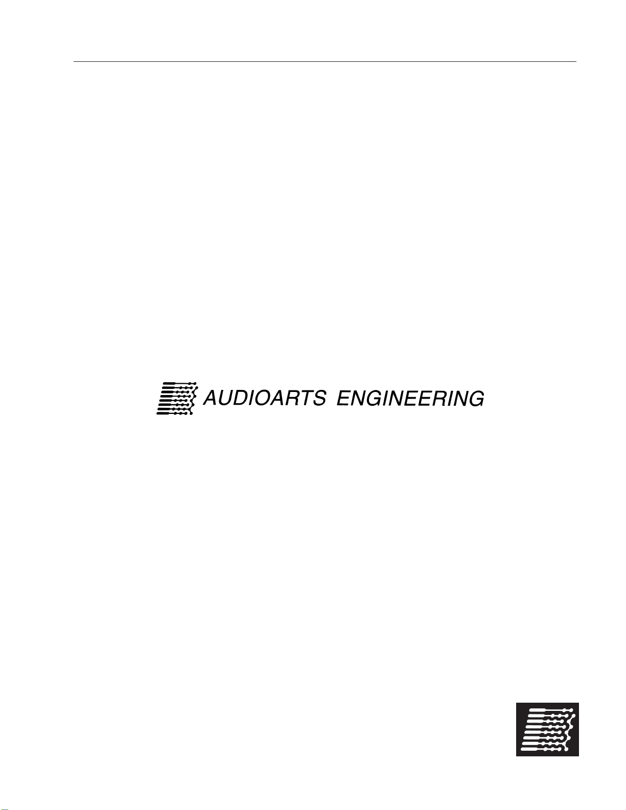
All audio I/O connections to the AIR 1 console are made via TRS and XLR
connectors located on the rear panel of the console.
TwoXLRfemaleconnectorsareprovidedtobringbalancedmonomicrophone
levelsignalsintotheconsoleforcontrolbythefirsttwo(microphone)faders.These
XLR connectors are wired “pin 2 hot.”
SixpairsofTRS(Tip-Ring-Sleeve)jacksareprovidedtobringbalancedstereo
line level signals into the console for control by (line) faders three through eight.
Thehighsideofthebalancedlineiswiredtothetip(T),thelowsideofthebalanced
line is on the ring (R), and the sleeve (S) is connected to the console ground. The
tip and ring are automatically switched to ground when there is no matching plug
inserted in the jack.
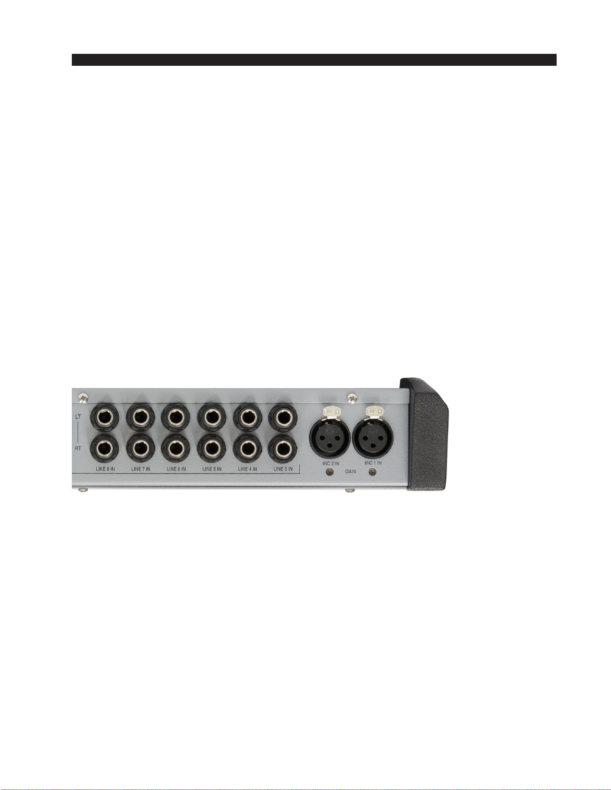
OnepairofTRSjacksisprovided to bring an additionalstereolinelevelsignal
into the console for use by the monitor circuits. These are also wired with the tip
high, the ring low, and the sleeve ground, and with automatic grounding when no
plug is inserted.
Two pairs of TRS jacks are provided to bring the two stereo program outputs
(PGM 1 and PGM 2) out of the console as balanced line level +4dBu signals. The
tip is high, the ring is low, and the sleeve is ground.
One pair of TRS jacks is provided to bring the stereo monitor output out of the
consoleasseparate (left andright)unbalanced line levelsignalsat a nominallevel
of -2dBu (equivalent to one side of a balanced +4dBu output). The tip is high and
both the ring and the sleeve are connected to ground.
One TRS jack is provided to bring the mono cue out of the console as an
unbalancedlinelevelsignal(nominal-2dBu).Thetipishighandboththeringand
the sleeve are connected to ground.
One TRS is provided for the operator to plug in a set of headphones. This is
wired as a standard headphone jack, with the left signal on the tip, the right signal
on the ring, and the sleeve conne cted to ground.
One TRS jack is provided to hook up an interface to an Air Tally light. This
outputcomesfromasetofrelaycontactsandisdesignedtoswitchalowDCvoltage
(30 VDC maximum) at a moderately low current (2 ADC maximum) to activate
a DC light, or to activate an external DC relay which can then be used to activate
anACoperatedlight.NeverbringACpowerintotheconsoleonthisoranyother
connector. The relay normally open (N.O.) contact appears on the tip and the
common contact appears on the ring. The sleeve is connected to ground.
One remaining TRS jack on the rear panel is not used.
A 5-pin DIN connector is provided to accept console power from the external
power supply.
AIR 1 / Jan 2008
INSTALLATION and POWER
page 1 – 5
AIR 1 / Dec 2007
Unbalanced Connections (analog audio)
ANALOGINPUTS— Wiretothe consolewithtypical shieldedtwoconductor
cable (like Belden 9451), just as if you were connecting a balanced source. At the
unbalanced source machine’s output, connect the black wire (LO) to the shield.
ANALOG OUTPUTS — The AIR 1 console’s PGM 1 and PGM 2 line level
analog outputs are electronically balanced, low impedance, outputs, expecting a
minimum load of 600 ohms. The outputs are balanced but are not floating.
Therefore, care must be exercised when connecting them to an unbalanced
system.While temporarily shortingthe low sideof the outputsignal to groundwill
not cause any problems, continued operation under these conditions will result in
increaseddistortion,decreasedreliability,andpossibleoscillationproblems.Ifyou
mustconnectoneoftheseoutputstoanunbalancedsystem,besuretoleavethe
low side unterminated, and connect the unbalanced system to the high side
output and shield connections only.
Hook-Ups
TherearoftheconsolehasmultipleTRSconnectorstoplugin6stereolineinputs
and the external input, as well as providing program 1 and 2, monitor, cue,
headphone,andtallyoutputconnections.TherearealsotwofemaleXLRconnectors
provided for microphone MIC 1 and MIC 2 inputs.
MIC 1 and MIC 2 Inputs
All signals are analog mono. The mic input level is normally -50dBu balanced.
PIN 1 XLR 1 SH – MIC 1 IN SH
PIN 2 XLR 1 HI – MIC 1 IN HI
PIN 3 XLR 1 LO – MIC 1 IN LO
PIN 1 XLR 2 SH – MIC 2 IN SH
PIN 2 XLR 2 HI – MIC 2 IN HI
PIN 3 XLR 2 LO – MIC 2 IN LO
LINE 3 IN through LINE 8 IN
Thetop TRS jack(TRS 1) isLEFT and thebottom TRS jack(TRS 2) isRIGHT
for each channel. All signals are analog stereo, +4dBu balanced.
TRS 1 TIP – LINE X LEFT HI
TRS 1 RING – LINE X LEFT LO
TRS 1 SLEEVE – LINE X LEFT SH
TRS 2 TIP – LINE X RIGHT HI
TRS 2 RING – LINE X RIGHT LO
TRS 2 SLEEVE – LINE X RIGHT SH
INSTALLATION and POWER
page 1 – 6
AIR 1 / Dec 2007
EXT IN
ThetopTRSjack(TRS1)isLEFTandthebottomTRSjack(TRS2)isRIGHT
for each channel. All signals are analog stereo, +4dBu balanced.
TRS 1 TIP – EXT LEFT HI
TRS 1 RING – EXT LEFT LO
TRS 1 SLEEVE – EXT LEFT SH
TRS 2 TIP – EXT RIGHT HI
TRS 2 RING – EXT RIGHT LO
TRS 2 SLEEVE – EXT RIGHT SH
PGM 1 OUT and PGM 2 OUT
ThetopTRSjack(TRS1)isLEFTandthebottomTRSjack(TRS2)isRIGHT
for each channel. All signals are analog stereo, +4dBu balanced.
TRS 1 TIP – PGM X LEFT HI
TRS 1 RING – PGM X LEFT LO
TRS 1 SLEEVE – PGM X LEFT SH
TRS 2 TIP – PGM X RIGHT HI
TRS 2 RING – PGM X RIGHT LO
TRS 2 SLEEVE – PGM X RIGHT SH
MONITOR OUT
ThetopTRSjack(TRS1)isLEFTandthebottomTRSjack(TRS2)isRIGHT
for each channel. All signals are analog stereo, -2dBu nominal, unbalanced.
TRS 1 TIP – MONITOR LEFT HI
TRS 1 RING – GROUND
TRS 1 SLEEVE – MONITOR LEFT SH
TRS 2 TIP – MONITOR RIGHT HI
TRS 2 RING – GROUND
TRS 2 SLEEVE – MONITOR RIGHT SH
CUE
Analog mono, -2dBu nominal, unbalanced.
TRS TIP – CUE HI
TRS RING – GROUND
TRS SLEEVE – CUE SH
HDPN
Analog stereo, headphone level, unbalanced.
TRS TIP – HDPN LEFT
TRS RING – HDPN RIGHT
TRS SLEEVE – HDPN SH

INSTALLATION and POWER
page 1 – 7
AIR 1 / Dec 2007
TALLY
Relay closure, 30VDC, 2A maximum.
TRS TIP – TALLY N.O.
TRS RING – TALLY COM
TRS SLEEVE – GROUND
SPARE
Not used.
TRS TIP – NO CONNECTION
TRS RING – NO CONNECTION
TRS SLEEVE – GROUND

page 2 – 1
AIR 1 / Dec 2007
CONSOLE FEATURES
Console Features
Chapter Contents
Overview ..................................................................................... 2-2
Inputs .......................................................................................... 2-4
Analog Mono Mic Level Inputs ............................................................................... 2-4
Analog Stereo Line Level Inputs ............................................................................ 2-4
Outputs ....................................................................................... 2-5
Program Outputs .................................................................................................... 2-5
Monitor Output ........................................................................................................ 2-5
Cue to Monitor ................................................................................................... 2-5
Split Cue, Monitor .............................................................................................. 2-6
Split Cue, Headphone ....................................................................................... 2-6
Monitor Mute...................................................................................................... 2-6
On Air Tally ........................................................................................................ 2-7

page 2 – 2
AIR 1 / Dec 2007
CONSOLE FEATURES
Console Features
Overview
TheAIR1consoleconsistsofaninputsectionwitheightfadersandassociated
switches,monitorandheadphonesectionwithtwofadersandassociatedswitches.
Thebasicpurposeofthe console istotakesomeof the manyaudiosignalsthat
are wired to the console inputs, and generate several outputs that combine these
inputsinvariousgroupsandatvariousdegreesofloudness,orsignalstrength.The
typicalapplicationisinaradiostationwhereitisdesiredtodevelopthesignalsthat
the station will broadcast (the on air signal), as well as several additional signals
for recording and monitoring.
Allprogramming ismade via PCB mounted slideswitches accessiblethrough
openings in the console’s bottom panel.

page 2 – 3
AIR 1 / Dec 2007
CONSOLE FEATURES
AIR 1 Bottom Panel

page 2 – 4
AIR 1 / Dec 2007
CONSOLE FEATURES
Inputs
The AIR 1 console is designed to handle 6 analog stereo (+4dBu balanced)
inputs, two mono microphone (-50dBu balanced) inputs, and one external stereo
line level (+4dBu balanced) input that goes directly to control room or meter.
Analog Mono Mic Level Inputs
These inputs are used to connect to microphones, which typically put out
signals at relatively low signal strength, and therefore require more amplication
(increase in signal strength) to be properly audible in the output. Mic level sources
are wired to female XLR connectors located on the rear of the console. These mic
inputs feed the console’s rst two faders. The mic preamps are set for a gain of
54dBu, but each mic pre has its own recessed GAIN control, located beneath the
XLR input connector, to allow eld adjustment to compensate for differences in
microphone characteristics.
Example: with a microphone input of –60dBm @150 ohm at the port, gain
trim can set levels from -22dBu to +16dBu (note maximum preamp gain is
+76dB) at the PGM 1 or PGM 2 output.
Analog Stereo Line Level Inputs
These inputs are typically used to connect to machines, such as tape decks, cart
machines, CD players, etc., that provide analog outputs.All six input line level signals
and external signal are switchable between -4dBu and +4dBu via slide switches,
LINE 3 - LINE 8 (SW 8 - SW 3 on MBA1-1 PCB) and EXTERNAL (SW 2 on
MBA1-1 PCB), accessible through openings in the console’s bottom panel.
When UP the input level signal is -4dBu;
When DOWN the input level signal is +4dBu.
AIR 1 / Feb 2014

page 2 – 5
AIR 1 / Dec 2007
CONSOLE FEATURES
Outputs
Theconsoleoutputsincludetwoprogramstereobusses(PGM1andPGM2),
a stereo monitor output, a mono cue output, and a stereo headphone jack.
The console’s mono cue signal is provided to drive an external powered
speaker,or amplifier and speaker combination,and alsoprovides the cue signal
usedto interrupt monitorand headphones, if such interrupthas been enabledby
the installer.
Program Outputs
The console’s main analog outputs are the two Program stereo buses
(PGM 1 and PGM 2). The Program stereo outputs can be programmed to
monooutputsviaslideswitches,PGM1MONOSUMandPGM2MONO
SUM (SW 11 and SW 12 on MBA1-1 PCB).
WhenSW 12is UP the PGM 1 is inmono mode,which sumsthe left
and right PGM 1 channels and sends this mono signal to both left and
right channels of the PGM 1 output.
When SW 12 is DOWN the PGM 1 is in stereo mode.
WhenSW 11is UP the PGM 2 is inmono mode,which sumsthe left
and right PGM 2 channels and sends this mono signal to both left and
right channels of the PGM 2 output.
When SW 11 is DOWN the PGM 2 is in stereo mode.
Monitor Output
TheAIR1hasaMONITORoutputdesignedtodriveastereopairofpowered
speakers,orastereoamplifierdrivingseparatespeakers,toallowtheoperatorto
listen to either PGM 1 or PGM 2, or an external signal. The console
may be programmed to mute the monitor or to provide monitor and
headphone split cue.
Cue to Monitor
TheCUE TOMONITOR (SW1 onMBA1-1 PCB)slide switch,
when activated (UP), sends cue to the monitor.

page 2 – 6
AIR 1 / Dec 2007
CONSOLE FEATURES
Split Cue, Monitor
TheMONITORSPLITCUE(SW3onMBA1-1PCB)slide
switch,whenactivated(UP),allowsasummed(L+R)versionof
the regular program to be sent to the right side of the monitor
stereo output, while CUE is sent to the left side.
Split Cue, Headphone
For headphones, consoles are normally programmed at the
factory for CUE to appear on the left channel, while the L+R
sum of the monitor output appears on the right. This can be
changedwiththeHEADPHONESPLIT CUE (SW4onMBA1-1PCB) slide switch.
Todefeatthissplit cue option,turntheswitchoff(DOWN).Withthissettingcuewill
interrupt both sides of the headphones.
Monitor Mute
The console has the ability to mute the monitor output.
TheconsolealsohasanONAIRtallyoutput that is usedto
drive user-provided external circuitry that will in turn
operate the ON AIR indicator. This tally is automatically
activated whenever the monitor mute is activated.
The two microphone channels can be programmed via
MIC1andMIC2(SW9andSW10onMBA1-1PCB)slide
switchesto mute themonitor speakerswhenthe channelis
ON. When MIC 1, SW 10, is UP the console’s monitor speakers are automatically
muted when the MIC 1 channel is turned ON.
When MIC 2, SW 9, is UP the console’s monitor speakers are automatically
muted when the MIC 2 channel is turned ON.
Thisisdonetopreventfeedbackfromthemonitorspeakertotheannouncer’smic.
At the same time that muting is enabled (by turning on either of the two MIC
channelswhenset toactivatethemonitormute),theONAIRLED inthecenterofthe
meterbridge is also turned on, and a closure is provided at the TALLY output to
activate the external circuitry for the ON AIR indicator.

page 2 – 7
AIR 1 / Dec 2007
CONSOLE FEATURES
On Air Tally
Forcontrollinganexternal“on-air”indicator,arelayisprovided.Thetally
is activated when a mic channel set for monitor mute is turned on.
The relay connections are available at the “TALLY” TRS connector
mountedontherearoftheconsole.Connecttheon-airlighttotheexternaluser-
provided relay. Do not bring on-air light AC connections to any pin of any
connector on the console.
"TALLY" TRS
CONNECTOR PIN YOUR
POWER
SUPPLY
–
TYPICAL MONITOR ON-AIR TALLY CIRCUI
T
USER-SUPPLIED RELAY TRIGGERED BY CONSOLE MONITOR MUTE CIRCUI
T
+
INTERNAL AIR
TALLY RELAY
COM
+
–
1N4002
ECG
B40240
or equiv.
relay
RELAY CIRCUIT POWERED BY USE
R
SUPPLIED EXTERNAL SUPPLY
N.O.
N.C.
2A
max
30VDC PIN
R
PIN
T

page 3 – 1
AIR 1 / Dec 2007
CONTROLS AND FUNCTIONS
Controls and Functions
Chapter Contents
Input Section .............................................................................. 3-2
Source..................................................................................................................... 3-3
Program Assign ...................................................................................................... 3-3
Cue Button .............................................................................................................. 3-3
Fader....................................................................................................................... 3-3
ON Button ............................................................................................................... 3-3
Master Section............................................................................ 3-4
Monitor .................................................................................................................... 3-5
Program Select .................................................................................................. 3-5
EXT Switch ........................................................................................................ 3-5
Monitor Fader .................................................................................................... 3-5
Cue Level Control.............................................................................................. 3-6
Headphone Fader.............................................................................................. 3-6
Meters ..................................................................................................................... 3-6
VU Meter Pair .................................................................................................... 3-6
Meter Select Buttons ......................................................................................... 3-7
On Air LED.............................................................................................................. 3-7
page 3 – 2
AIR 1 / Dec 2007
CONTROLS AND FUNCTIONS
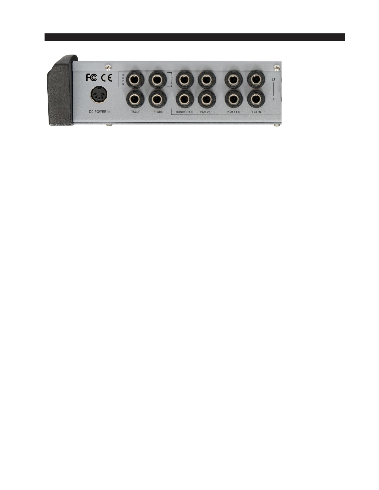
Controls and Functions
Input Section
The AIR 1 Input section consist of two mono microphone input channels and
six stereo analog input channels.
TheMICandLINEinputchannelshavethesamecontrols,exceptthattheMIC
channels don’t have a CUE switch.
Other manuals for AIR 1
2
Table of contents
Other AudioArts Engineering Music Mixer manuals

AudioArts Engineering
AudioArts Engineering AIR 1 Quick start guide

AudioArts Engineering
AudioArts Engineering audio console r-55e User manual

AudioArts Engineering
AudioArts Engineering AIR 1 User manual

AudioArts Engineering
AudioArts Engineering AIR 2+ User manual

AudioArts Engineering
AudioArts Engineering DMX-8 Assembly instructions

AudioArts Engineering
AudioArts Engineering Audioarts 08 User manual

AudioArts Engineering
AudioArts Engineering Lightning User manual


