Tollco WaterFuse - House Specification sheet

1 (20)
WaterFuse®- House
User Manual
&
Installation Instruction

2 (20)
Thank you for choosing the WaterFuse® water switch.
We hope that the WaterFuse® will meet your expectations for a simple
but effective protection against water damage due to damaged pipes or
equipment. This product is developed for detached houses, holiday homes
and terrace houses. The manual is divided into two parts, one for the user and
one for the installer, in order to provide simple and clear instructions for the
user and the necessary information for the installer.
Safety
Read this manual carefully and follow the instructions for placement and
usage.
The product may only be connected by a qualified installer. The warranty does
not cover repairs of faults caused by faulty installation or incorrect use of the
appliance.
Recycling
Used products must be left at a collection point for the recycling of electrical
and electronic components. By ensuring that the product is handled correctly,
you help to prevent any negative environmental and health effects that may
occur if the product is disposed of as normal waste. For further information
on recycling, please contact local authorities, your household waste disposal
service, or the shop where you purchased the item.
Edition 11/02/2020
!

3 (20)
Table of Contents
1. User Manual 4
1.1. General information
about the product 4
1.2. The Different Parts 5
1.3. Daily Operation 6
1.4. Alarm 7
1.5. Faults 8
1.6. Menu system 8
1.7. Settings 9
1.8. Troubleshooting Water Leak 10
1.9. Troubleshooting Radio
Communication 10
2. Installation Instructions 11
2.1. General Information 11
2.2. Installation 12
2.3 Connection to house alarm system
or other remote control 14
2.4. Settings 16
2.4.1. Connected units 16
2.4.2. Search for new device 16
2.4.3. Pressure Drop Measurement 17
2.4.4. Volume Measurement 17
2.4.5. Temperature Limit 17
2.4.6. External Alarm 17
2.5. Troubleshooting Water Leak 18
2.6. Troubleshooting Radio
Communication 18
3. Technical Specification 19
4. Warranty and Limitation
of Liability 19

4 (20)
User Manual
1.1 General information about the product:
WaterFuse® - House reduces the risk of water damage by allowing you to simply turn off the
water, pressure test the PHS system and giving you water detectors that turn off the water
supply when there is a water indication.
A motorised shutoff valve, which electronically turns the water on or off in the entire property
is mounted right after the water meter. The pressure sensor measures the pressure in the water
system to check for a water leak by measuring the pressure drop in the closed water system.
Note! The pressure sensor is not included in House Basic, which is otherwise identical to House.
The motorised valve is controlled by the central unit, which in turn can be controlled by remote
unit(s). The water detectors function similarly to a smoke detector, but for water. If they indicate
water, a signal is sent to the central unit which automatically shuts off the water. There is also a
temperature sensor in the water detectors that can be used to turn the water off if there is a risk of
frost damage.
As the water switch is installed, a washing machine can also be placed in the kitchen without
a floor drain, if there is a waterproof surface and a water sensor is placed so that any water
leaking from the equipment can be detected so that the leak can be automatically stopped. This
of course also applies to other pressurised equipment, such as dishwashers, coffee makers and
refrigerator/freezer with automatic water supply.
Components
– Central unit, art. no. 2220052 – Water unit, art.no 2120012 – DC adapter
– Remote unit, art.no 2220022 (option)
– Water detector with sensors, art.no 2220042 (option)
The product is delivered in different packages; not all of them include the above components.
The products are labelled with the article number and manufacturing date.

5 (20)
1.2 The Different Parts:
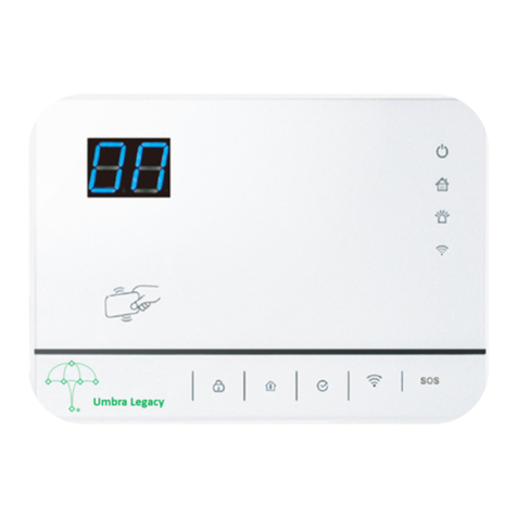
Central unit:
The unit provides all information about the system and you use it for all
settings. The central unit controls the water unit and receives signals from
the wireless units. The arrows and OK button are used to navigate the menu
system. Using the arrows and the OK button, you can also select different
settings and confirm your selections. The display has corresponding arrow
symbols showing you how to navigate. Press OK to confirm or go to the
subsequent level of the menu system.
The menu option Back moves you one level up in the menu system. Returns to the basic menu
after two minutes of no activity.
Installed in a suitable place in the area around the water unit.
Water unit:
Motorised ball valve to turn the water ON and OFF. The unit is intended for
tap water, 0–60°C and 0–10 bar.
The pressure sensor measures current water pressure in the property’s
water system. It can also be manually operated with a mechanical knob on
the unit if the power goes out. Lift the knob 5 mm and turn clockwise to
close the valve. See indicator.
Fitted after the water meter.
Remote Unit:
Controls the central unit. When you press a button, the LED will flash until
it receives a verification from the central unit that the desired measure is
complete. The LED will then stop flashing for a moment before turning off.
Suitable placement by the door.
Water detector:
Each water detector comes with three sensors, which are placed in suitable
locations. The water sensor transmits a radio signal and gives off a
pulsating sound signal if it detects water. When the temperature drops below
5 degrees, it sends the temperature indication to the Central Unit to possibly
turn off the water. The water sensor sends an “I’m alive” signal every 24h to
the central unit with information regarding battery voltage and transmission
quality. The following are different solutions for installation:

6 (20)
Underneath dishwasher and sink unit or kitchen island with a sink:
One sensor on the plastic cover underneath the dishwasher, one sensor on the floor underneath the
sink and the final sensor in the shaft where the pipes emerge from the floor or in the door threshold.
Underneath refrigerator/freezer with water supply:
One sensor underneath the monitored equipment.
In the laundry room or bathroom:
In these areas, there is sometimes water splashing during regular use;
the floor must be waterproofed and there must be a functioning floor
drain. Place the sensor (or sensors) where they will only touch water in
case of a leak resulting in rising water level, such as the threshold.
1.3 Daily Operation:
When you leave home
• Press OFF on the remote unit. This turns off the water in the entire property.
• If you want the water to stay on for a limited period of time, press the button “delayed OFF” .
The water stays on for the period set on the central unit, where you can choose 1–4 hours. The
water is then turned off in the entire house.
When you come home
• Press ON on the remote unit. This turns the water on in the entire property.
• If you have had a leak while you were away, the verification signal will pulsate and the LED “ALARM”
will flash on the remote unit to indicate a drop in pressure. The central unit will also display written
text. Most often, the problem is a leaky faucet or running toilet. But if it happens every time you come
home, and you cannot locate the leak, it is time for a check.
See “Troubleshooting water leak”.
Automatic pressure drop measurement
• Automatic pressure drop measurement is conducted once per day by shutting the valve. The result is
shown on the display and on the remote unit. The test is described in more detail in section 2.1
• If you do not want this measurement to be conducted, it can be deactivated, see section 2.4.

7 (20)
1.4 Alarm:
• The water sensor indicates water
If a water sensor has identified water, the water is automatically turned off in the whole
property. The water sensor gives off a pulsating alarm signal for as long as it can identify water.
The central unit gives a pulsating alarm signal and the display indicates in text which water
sensor has been triggered, until the alarm is “Confirmed” or “Ignored” by you.
You cannot activate the water; if you try to turn on the water, the LEDs for OFF and ALARM will
light up together with a long beeping sound to prevent you from turning on the water without
first fixing the problem.
The central unit will show which unit triggered the alarm and the buzzer will sound. Press OK
once for further information. Then select “Confirm” to turn the alarm off and enable you to
turn the water back on, or “Ignore” to turn the alarm off and start searching for water by the
triggered water sensor. Press “Confirm” when the fault has been rectified and the water can be
turned back on.
• Temperature Alarm
If the temperature around any water sensor drops below the set trigger value, the water will be
automatically turned off. The central unit gives a pulsating alarm signal and the display indicates
in text which water sensor has been triggered, until the alarm is “Confirmed” or “Ignored” by
you.
• A pressure drop has occurred
Indicated by a sound signal and display text as well as the “ALARM” LED flashing on the remote
unit when you press any button. The system has identified a pressure drop due to a leak in the
water system. Usually a faucet or toilet. Under advanced settings, you can decide if the water
should remain off after an identified pressure drop or not. The water can still be turned back on
after verification. The unit will sound the alarm once in a while, but if this happens repeatedly
and you cannot find a running faucet or toilet, there is a leak that needs to be fixed.
See “Troubleshooting water leak”.

8 (20)
1.5 Faults:
• Error codes
If the central unit has detected an error, it is written in text on the display. The “ALARM” LED
will light up on the remote unit and a constant tone will sound for a second.
• Low battery
If the battery voltage is too low in either unit, the LEDs will flash on the remote unit rather
than staying lit when the verification signal is transmitted from the central unit. The sound
signal is different too. The central unit displays in text which unit requires a battery change.
The batteries have an expected life of at least 2 years in normal use. The electronics remain
functional down to a battery level of 2.3v.
• Radio Communication Error
If the radio communication between different units malfunctions, or does not function suf-
ficiently, the LEDs on the remote unit will flash until they go off, without ever being constantly
lit. The central unit shows text on the display indicating which unit is having trouble with
radio communication. This is usually because something has changed in the home since the
last time the radio communication was functioning. It could for example be because there are
too many metal containers underneath the sink blocking the sensor in the cupboard.
See “Troubleshooting radio communication”.
1.6 Menu system:
The menu system is not necessary for the daily use of the product. See “Daily Operation”. For the
user, only six of the menu entries are of interest.
1. Current water level (normal menu, the system automatically returns here after 2 minutes of no
activity)
2. Water Pressure (Indicates current water pressure in the property, regardless of whether the
water is on or off. Note! Only if a pressure sensor has been installed.)
3. Water Volume (Shows the most recent water volume and the maximum water volume.
Note! Only if a water meter has been installed.)
4. Alarm (Shows if any alarm is active)
5. Error (Shows a pressure drop or if some unit is not working properly)
6. Settings (This option opens the setting menus). The first menus are for user
information purposes only.
The “Settings” menu allows you to make changes to the system settings, read more under “Settings”.

9 (20)
1.7 Settings:
Before you make any changes to the settings, you should be aware of what you are actually
changing. You should therefore read through this section before you begin. Upon installation, the
settings have been tuned to fit your property.
Go down through the menu until to come to “Settings”, press OK.
Settings
1. Delayed OFF
2. Start, Water OFF or RESET
3. In case of a pressure drop, water ON or OFF (Only displayed if pressure sensor has been installed)
4. Water volume limit (Only displayed if a water meter has been installed)
5. Language
6. Advanced settings
7. Back
The following is a description of the different settings
1. Delayed OFF
Used to determine how long the water will remain on before being turned OFF if you press “Delayed
OFF” when you exit the property. This allows your dishwasher or washing machine programme to
finish even if you leave.
Can be set to 1–4 hours, with 2 hours as the standard.
2. Start, Water OFF or RESET
When the unit is started, for example after a power outage, should the water be turned OFF or
remain in the same position as before the outage? The risk of water damage (frost damage) in
conjunction with a power outage is high. Water damage can be avoided by turning off the valve
after a power outage. Can be set to OFF or RESET to latest position. The standard setting is OFF.
3. In case of pressure drop, water ON or OFF
If a pressure drop measurement conducted automatically, or because you have turned on the water,
warns of a leak. Should the water be ON (for automatic test), be possible to turn ON (if you have
turned the water off) or OFF (you must then confirm in the central unit before you can turn the
water back on. The standard setting is ON.
4. Water volume limit
Set using the arrows and saved with OK.

10 (20)
5. Language
Choose the language that suits you.
6. Advanced settings
Should not be used by the regular user.
See Installation Instructions for more information.
1.8 Troubleshooting Water Leak:
During the installation of WaterFuse® a check is done to verify that there are no leakages in the
water system. If there is a pressure drop indication, carry out the followign simple checks to
identify the leak:
Press OFF on the central unit. Go one step down in teh menu and check the current water
pressure. Is it dropping rapidly or slowly? This will give you an indication of the size of the leak.
If a faucet drips once every second, the pressure disappears almost immediately. WaterFuse®
will warn you already around one drop per minute.
Once the leak has been identified, it must be remedied, by the user or by a plumber. If you are
unable to locate the lead, contact your plumber for troubleshooting.
Tips for troubleshooting
Water faucets:
The check is most easily conducted by placing a piece of paper underneath the faucet for a
few minutes to see if any drops fall on the paper. It is easy to forget the faucets of the shower,
bathtub, garden or garage.
Toilets:
Toilets are checked by turning them off using the shut-off valve.
Other equipment:
Check connections to washing machine, dishwasher, etc. for leaks.
1.9 Troubleshooting Radio Communication:
If the central unit has lost the radio communication with the external units, it could be due to
changed conditions. Some new object has been added that interrupts the radio signal; tin cans under
the sink that block the signal is the most common problem, but new wires or electric equipment
within 50 cm from one of the radio units could also be the cause.
See section 2.6 for more information.

11 (20)
2 Installaon Instrucon
2.1 General Information:
The product must be installed by a person who has the professional knowledge required to perform
the installation correctly. Unless the installation is performed by a professional, the insurance
companies may claim that the insurance does not cover any damage that has occurred and that the
offers made by the insurance companies to the property owner are invalid.
The radio communication goes two ways between the wireless units and the central unit to secure
the quality of transmission.
The wireless units transmit a signal every 24 hours that is registered by the central unit. If no signal
is received by the central unit in 72 hours, it will warn that communication is down. A total of 16
external units can be installed, freely mixed between remote units and water sensors.
The ball valve is exercised on a daily basis through the closing/opening carried out as the water is
turned off or on. If the ball valve is open for more than three days, it will be automatically exercised,
but the water will not be completely turned off.
There are two pressure drop tests that can be conducted.
1. The pressure drop test is conducted by taking a reference measure when the ball valve has closed
after the user has turned the water off using the OFF, delayed OFF or alarm. The system then waits
15 minutes before taking the next and final measurement. If the difference in pressure is more than
1 bar, the system considers a leak to exist and informs the user via display or LED on the remote unit.
You can choose whether to allow the water to be turned on or if the fault must first be confirmed.
2. Automatic pressure drop test. An automatic pressure drop test is conducted once every 24 hours.
It is carried out by shutting off the water and any pressure drop in the water pipe is measured
three times with 15-minute intervals. If there is no pressure drop exceeding 1 bar in any of these
three measurements, the system will wait 24h and then do the test again. The system thus accepts
consumption on two out of three measuring occasions.
The measurement is done in the following way:
Measurement 1. The water is automatically turned off and the measurement begins. If there is a
pressure drop, the water will immediately open again and a new measurement is done 1h later.
Otherwise OK and wait 24h until next measurement.
Measurement 2. The water is automatically turned off and the measurement begins. If there is a
pressure drop, the water will immediately open again and a new measurement is done 1h later.
Otherwise OK and wait 24h until next measurement.

12 (20)
Measurement 3. The water is turned off automatically. If it again identifies a pressure drop, the system
triggers the alarm. The water remains turned off or can still be turned on depending on the software
setting.
If the system finds that the normal consumption during measurement 1 or 2 is high, and the final
measurement shows a closed system, the time is shifted forward by 4h until the subsequent 24 hours.
The system thereby automatically adjusts to the time when it is most likely that there is no water
consumption.
A washing machine can also be placed in the kitchen without a floor drain, if there is a waterproof
surface and a water sensor is placed so that any water leaking from the equipment can be detected so
that the leak can be automatically stopped. (In accordance with Safe Water Installation 2016:1 Chapter
3.6. 3) This of course also applies to other pressurised equipment, such as dishwashers, coffee makers
and refrigerator/freezer with automatic water supply.
The products are labelled with the article number and manufacturing date.
2.2 Installation:
Water unit:
The unit is intended for tap water, 0–60°C and 0–10 bar. Fitted after the water meter and the main
water line with the motorised ball valve against the water meter.
The valve can be mounted in any position: horizontally, vertically, or upside down. The unit has an
internal R-thread. Connect to pipe, for example with compression fittings according to the installation
instructions from the pipe and fitting manufacturer. Use the necessary sealing compound.
The unit must not be fitted in a concealed location, and must be placed so that it can be changed and so
that any water leaks can be detected. The unit must be installed in a room with waterproof flooring, in
a distribution cabinet, or in a custom space. If a distribution cabinet is used, the installation instructions
for this must be followed. After mounting, the installation must be checked for leaks with the tap water
installation’s existing water pressure according to the instructions at www.säkervatten.se
Note! If there is emergency cooling of heating equipment, sprinkler system or similar in the
property, the installation must allow such equipment to maintain their function.
Flow direction
!

13 (20)
Central Unit: (art. no. 2220052)
Installed in a suitable place in the area around the water unit. Check so that no
electrical cables or installations are found within 50 cm of the equipment, as this
disturbs the radio transmission. The box on the bottom has two “buttons” used to
open it. The back piece is attached to the wall with screws. Cable to the water unit
and the DC adapter is connected and the electronic unit is put back in place.
The DC adapter that comes with the product must be used for power supply.
First start-up
Connect the DC adapter of the central unit to a 230vac socket. Press ON to turn on the water, check
that normal water flow is possible. Inspect all new joints for minor leaks. In the menu system, press
the downwards arrow once to show the current water pressure. Then turn off the water main, the
pressure senso should now show the water pressure in the whole closed tap water system. Any
pressure drop that occurs at this point is due to a leak in the property’s water system. If the pressure
drops by more than 0.1 bar (measurement inaccuracy) in 15 minutes, troubleshoot the water system
to identify the leak and fix it. The open the water main for normal operation.
Remote Unit: (art. no. 2220022)
Place in an easily accessible place near an outer door. Check so that no electrical cables
or installations are found within 50 cm of the equipment, as this disturbs the radio
transmission. The box on the bottom has two “buttons” used to open it. Install two new
AA batteries in the battery compartment according to instruction. The back piece is
attached to the wall with screws and the electronic unit is put back in place.
Water sensor: (art. no. 2220042)
The sensors that come with the product are placed in the location
intended to be protected. For example by the dishwasher and sink: One
sensor underneath the dishwasher, one sensor on the floor underneath
the sink and the final sensor in the shaft where the pipes emerge from
the floor or in the door threshold.
For additional placement suggestions, see section 1.2.
Check so that no electrical cables or installations are found within 50 cm
of the equipment, as this disturbs the radio transmission. The box on the
bottom has two “buttons” used to open it. Install two new AA batteries
in the battery compartment according to instruction. The back piece is attached to the wall with
screws and the electronic unit installed in a suitable location.
(The wireless units packaged with the central unit are pre-programmed to communicate together
and do not need to be installed according to the instructions below.)
“Buttons”
“Button”

14 (20)
Then put the batteries in the remote unit(s) and place in the intended location. When the battery is
placed in the unit, it will start up in installation mode. This means that in the first five minutes, it will
transmit an installation signal every 15 seconds. Go into the menu on the central unit, select “Settings”
and then “Advanced Settings”, then “Search for new unit”, then press OK. The new unit is displayed,
“Connect?”, press OK. Now you can select a suitable name for the unit from a list, “Select name”, press
OK The unit is now connected and will remain connected also during a battery change.
Then put the batteries in the water sensor(s) and place in the intended location. When the battery
is placed in the unit, it starts up in installation mode. This means that in the first five minutes, it will
transmit an installation signal every 15 seconds. Go into the menu on the central unit, select “Settings”
and then “Advanced Settings”, then “Search for new unit”, then press OK. The new unit should now be
displayed, “Connect?”, press OK. Now you can select a suitable name for the unit from a list, “Select
name”, press OK The unit is now connected and will remain connected also during a battery change.
Check radio transmission:
When the wireless unit has been installed in its place and the unit is in installation mode, the signal
strength of the transmission can easily be checked. Go into menu “Advanced settings” and then
“Connected units”, “Select unit” and move down to “RSSI”. A value lower than -60DBM is excellent
and between -60DBM and -85DBM is ok. Above -85DBM the units need to be repositioned to improve
radio communications. But a relatively stable transmission is possible up to -95DBM The level
indicated in RSSI is always the most recently measured signal strength of the radio transmission.
2.3 Connection to house alarm or other remote control
WaterFuse® can be connected to a master alarm or remote control system and thus become part of
the alarm system. This makes it possible to turn the water off or on via remote control, for example to
your holiday home or receive an alarm from a water sensor to your phone.
WaterFuse® has two output ports and one input port on the central unit for connection to a master
system. One of the output ports triggers the alarm in the event of urgent leaks detected by a water
sensor, the other in case a pressure drop has occurred. This means that when there is an alarm signal
from WaterFuse®, it is possible to have information sent to the same telephone number as for other
alarm signals. The ingoing port can be controlled in a number of different ways to turn the water on
or off as needed.
Connection
There is an 8-pole terminal block for connection to the alarm systems. The input and output ports use opto
connectors to protect the electronics.

15 (20)
The PINs are counted from left to right when connecting the cable.
Pin 1 Digital IN –
Pin 2 Digital IN +
Pin 3 Digital OUT1 –
Pin 4 Digital OUT1 +
Pin 5 Digital OUT2 –
Pin 6 Digital OUT2 +
Pin 7 Gnd
Pin 8 +12v
Digital OUT1
Used to send an alarm signal from the water
sensor to a master alarm system. Connected
in the same way as a door switch or similar.
No software installation is necessary.
Digital OUT2
Used to send an alarm signal from pressure drop
indication to a master alarm system. Connected
in the same way as a door switch or similar.
No software installation is necessary.
Digital IN
Used to control the water being turned on or off.
Static levels or Pulse can be used. In the case of
Pulse, you can only control either the ON or OFF
function however.
The following software settings can be made
Preferably connected as follows:
Jumper between Pin 8 and Pin 4.
Connect + of the alarm to Pin 3 and - of the alarm to Pin
7. In case of alarm indication Pin 3 will be 12v (Digital 1)
Preferably connected as follows:
GND One side on the breaking/closing pole Pin 1
(In-) Other side on breaking/closing pole Pin 2
(In+) Jumper to Pin 8 (+12v) alternatively
Pin 1 (In-) 0v (or GND) on alarm output Pin 2 (
In+) 12v on one alarm output
Such as property control or DC adapter
ON/OFF High level water On/Low level water Off
OFF/ON High level water Off/Low level water On
ON/F-OFF High level water On/Low level water Off delayed
F-OFF/ON High level water Off delayed/Low level water On
ON FOR PULSE Water on in case of pulse. The user shuts manually.
OFF WITH PULSE Water Off with pulse. The user opens manually.
F-OFF WITH PULSE Water Off delayed with pulse. The user opens manually.
Preferably connected as follows:
Jumper between Pin 8 and Pin 6.
Connect + of the alarm to Pin 5 and - of the alarm to Pin
7. In case of alarm indication Pin 5 will be 12v (Digital 1)

16 (20)
2.4 Settings:
There are a number of settings that can be changed for the product.
Setting Values Standard
Delayed OFF 1–4 hours 2 hours
Water OFF after a power outage OFF, Reset as before power outage OFF
At pressure drop Water ON or OFF Water ON
Volume limit 1L–100,000L 500L
Language Swedish, Norwegian, Danish, Finnish, English Swedish
Advanced setting
Connected units Handle wireless units
- RSSI Indicates the signal strength of the most recent radio communication.
- Temperature Shows current temperature (Only applies to water sensors)
- Battery level Shows current battery voltage and whether this is OK.
- Change unit name Change the name of an already installed unit -
- Remove unit Removes an installed unit -
Search for new unit Install wireless units -
Pressure drop measurement Automatic pressure drop measurement ON
Volume measurement Requires a water meter with digi. output port OFF
- Volume per pulse Set depending on water meter 1L/PULSE
- Volume limit At which water volume should turn OFF 500L
Temperature limit At which temperature should the water be turned off.
OFF, 1, 2, 3, 4, 5 degrees 3 degrees
External alarm Settings for external control ON/OFF
2.4.1. Connected units
In order to handle the function of already connected units, you can use the following menu selection.
First select which unit you wish to manage “Select unit” and press OK, then move down to the
desired function.
“RSSI”, Indicates the signal strength of the most recent radio communication.
“TEMPERATURE”, Shows current temperature, Only applies to water sensors.
“BATTERY LEVEL”, Shows current battery voltage and whether this is OK.
“Change name?”, easily change the name of a unit by moving down using the right/left arrows and
confirm by pressing OK.
“Remove?”, used to remove connected units.
Note! If a unit is no longer in use, it needs to be permanently removed from the system, if not, the
system will automatically expect the “I’m alive” signal from the unit every 24 hours and the central
unit will trigger the alarm with a “beep” signal every three minutes after three days, “LOST CONTACT”,
“DISHWASHER”.
2.4.2. Search for new device
Upon installation of an additional remote unit or water sensor to expand the system, you can use

17 (20)
this menu selection to easily add it to your system. The units transmit an installation signal every 15
seconds in the first 5 minutes after the batteries have been fitted. Press OK to search for a new unit,
when the system finds the new unit, it will ask you whether to “Connect?”, confirm by pressing OK.
You are then given the option to change the name of the unit from a list of predefined names by
using the right/left arrows, confirm by pressing OK.
2.4.3. Pressure Drop Measurement
If you want the automatic pressure drop measurement to be carried out every 24 hours, select ON. If
you only want the pressure test to be conducted when the user has turned off the water, select OFF.
2.4.4. Volume Measurement
If a water meter with a digital output port is connected to the system, select ON. A couple of new
menus will appear. “Volume per pulse” determines cl of water per pulse from the water meter.
1–10,000 cl (0.01L–10L) “Volume limit” determines how many litres of water flow are allowed before
the water is turned off. 1L–100,000L
2.4.5. Temperature Limit
If the temperature falls below the set value at any water sensor, the water will immediately be turned
off. Can be set to Off, 1, 2, 3, 4, 5 degrees. Standard 3 degrees.
2.4.6. External Alarm
Select a suitable setting according to section 2.4 for the communication with alarm or other control
system.

18 (20)
2.5 Troubleshooting Water Leak:
When the water is turned off, WaterFuse® automatically detects leaks from 5ml per hour, which
corresponds to around 1 drop per minute from a faucet. The product can measure and identify
even smaller leaks in manual mode, but then does not automatically inform the property owner. By
monitoring pressure in real time inside the property, you will gain an idea of the leak. The benefit of
WaterFuse® compared to the pressure drop test conducted in new properties or major installations is
that the measurement is conducted at normal pressure and thereby does not subject the water system
to overpressure. It can also be easily carried out and checked. (For full leak testing, see AMA YTC.15 or
Safe water installation 2007:1 section F1.)
In case of a pressure drop, check if there are any running faucets or toilets in the property. Unless the
pressure drop is detected there, continue to all connected devices, dishwashers, washing machines,
water heaters, etc. to check for leaks.
If the pressure drop still has not been found, there is a risk of a concealed leak. Narrow down
where in the system the leak is located and contact your insurance company if necessary for a joint
investigation.
2.6 Troubleshooting Radio Communication:
See section 1.9 if the radio communication was previously functioning.
If it is instead a troubleshooting for a new installation, try the following: Take the batteries out,
wait for 1 minute before putting them back into place. The units will then start with a “beep” in the
installation mode and transmit every 15 seconds for five minutes. This makes it easier to see if the
transmission effect is sufficient.
Go into menu “Advanced settings” and then “Connected units”, “Select unit” and move down to
“RSSI”. You will now see the signal strength for the latest transmission from the unit. The signal
strength should be over -85DBM, preferably under -60DBM. Remember that the units are intended to
be fitted on the wall and all antennas are therefore adapted to this purpose. During troubleshooting,
therefore hold the remote unit or water sensor vertically.
Detach the unit and bring it to the central unit to verify that the transmission works at a distance of
two–three metres. If not, the unit is not functioning and must be sent for repair/warranty. Note! It is
difficult for the unit to communicate at a distance of less than one meter due to its construction.
Now move the unit, on the same floor as the central unit, as close to the intended location as you
can and verify the signal strength. If it is still ok, (<-85DBM), change floors and move as close to the
central unit as possible. If it is still ok, (<-85DBM), move away towards the location where you want to
install it.
Try to gauge where it stops functioning and consider what could be blocking the signal. Equipment
containing a lot of metal, such as refrigerator, freezer, dishwashers and sinks are naturally difficult for
the radio signal to penetrate. If the property is made out of concrete, it is more difficult for the radio
transmission to penetrate than wood. If you have a radio signal near the location where you want to

19 (20)
install it, but not exactly where it will be placed, see if you can move it a little bit or if you can
move the central unit.
3 Technical Specicaons
ELECTRICITY PHS
230 vac for 12 vdc adapter G20 (DN20)
2 × AA 1.5 v batteries for the remote unit Pressure sensor 0-10
bar 2 × AA 1.5 v batteries for water sensor Motorised Ball Valve
with manual override.
The operational life of the batteries is expected to exceed 2 years.
Radio signal up to 40 metres indoors, depending on construction materials in the property.
4 Warranty and Limitaon of Liability
In addition to the terms of the Consumer Sales Act, a 1-year functional warranty is provided for the product.
The warranty stipulates that during normal use and maintenance, the product must be free from defects
in design and function. The warranty period is calculated from the date of purchase, which must be proven
by a receipt from the place of purchase. The warranty presupposes that the product has been installed
appropriately and in accordance with the written instructions. The plumbing installation must be completed by
a professional plumber.
If you have questions or problems with your product, you should first contact the dealer who sold or installed
your equipment. Before you report a fault /complaint about your broken product, please read the operating
instructions and, if possible, check that all settings are correct. The warranty stipulates that defective parts
or components will be replaced with defect-free ditto. The customer is responsible for all overhead, unless
the Consumer Sales Act is applicable. This means that shipping costs, inspection, and assembly costs are not
included in the warranty.
If possible, use the original packaging if the product needs to be transported. The transport companies do not
compensate for damage if the product has been poorly packaged
The warranty does not apply to defects that occur during or after making your own changes to the product’s
function or appearance, such as rebuilding, upgrading, or other configurations of the product made without
written approval.
The warranty does not cover faults that have arisen through an accident or malicious damage.
The warranty does not cover deterioration that has occurred after the purchase, if the seller can prove it
probable that the deterioration is due to neglected or incorrect maintenance or that the appliance has been
used something other than its intended purpose, that inappropriate measures, unauthorised or incorrect
interventions have been made or that installation instructions were not followed.
Batteries are considered consumables and are not covered by the warranty.
The reseller is not responsible for loss or damage of any kind caused by this product. The liability is, in any
case, strictly limited to the replacement of the product.

20 (20)
Tel: 018-34 90 10
info@tollco.se
www.tollco.se
Tollco AB
Rubanksgatan 4
741 71 KNIVSTA
Table of contents
