Tomco BTM00250 ALPHA-S Use and care manual

250W RF AMPLIFIER MODULE
MODEL BTM00250 ALPHA-S
OPERATION AND SAFETY MANUAL

TOMCO 250W RF AMPLIFIER MODULE
MODEL BTM00250 ALPHA-S
OPERATION AND SAFETY MANUAL
This handbook is provided in confidence, as a technical reference for use solely by the purchaser of the
equipment. The handbook or its contents may not be reproduced or distributed without written consent from
Tomco Technologies.
Tomco Technologies
17 Clarke St
Norwood SA 5067
AUSTRALIA
Ph +61 8 83642203
Fax +61 8 83642202
©Tomco Electronics Pty Ltd
July 2008
Document No. T003375 Issue A

CONTENTS
OPERATION AND SAFETY MANUAL .......................................................................................................1
AMPLIFIER SAFETY PRECAUTIONS ...................................................................................................1
HAZARDOUS MATERIALS WARNING:................................................................................................2
SAFETY SYMBOLS USED IN THIS MANUAL AND ON THE EQUIPMENT......................................3
TECHNICAL DESCRIPTION, OPERATING NOTES AND INSTALLATION NOTES....................4
INPUTS AND OUTPUTS...................................................................................................................................4
RF DRIVE input:.....................................................................................................................................4
GATE input: ............................................................................................................................................5
RF OUT connection.................................................................................................................................5
SIGNAL TIMING DIAGRAMS FOR PULSED OPERATION.....................................................................................6
STATUS INDICATORS.....................................................................................................................................7
DC power:...............................................................................................................................................7
RF power:................................................................................................................................................7
Overtemp:................................................................................................................................................7
COOLING AND THERMAL PROTECTION:.........................................................................................................7
STATUS/CONTROL INTERFACE .....................................................................................................................8
SPECIFICATIONS.......................................................................................................................................9

TOMCO TECHNOLOGIES, SOUTH AUSTRALIA
Amplifier Safety Precautions
EXTREMELY IMPORTANT
The amplifier is designed to generate large amounts of RF power, and can generate high
RF voltages. It is therefore capable of causing very serious injury unless the proper
safety precautions are carefully observed. To minimise the risk, all personnel involved
with operating or maintaining the amplifier must be thoroughly familiar with the following
safety precautions:
•Tomco linear amplifiers are capable of producing much more than their rated output
power. The amplifiers are designed such that an RF drive level of not more than
0dBm is required for full output power at any frequency. Applying more than 0dBm of
RF drive can result in more RF output power, as the amplifier enters compression. It
is safe to operate the amplifier in compression, provided that the RF drive level does
not exceed +10dBm.
•
The manufacturer has taken extensive precautions to ensure that unintentional
contact with hazardous voltages within the radar equipment is minimised. However,
all personnel involved in the operation of the amplifier must be aware that dangerous
voltages are present within the equipment, and on any load, probe or antenna
connected to its outputs.
•When the amplifier is operating, the RF field strength at various points in the near
field of the RF load, probe or antenna may exceed the safe continuous exposure
level specified in international standards. Personnel engaged in the operation or
maintenance of this equipment should be aware of, and avoid, extended exposure to
RF radiation.
•This is a high gain high power amplifier. As such, small amounts of unintentional
feedback or small unintentional inputs can result in large RF output levels. These
transient RF outputs are not only extremely dangerous, but may also cause
extensive damage to any load, probe or antenna connected to the amplifier’s output.
Also, take care to use only high quality well shielded 50 ohm coaxial cable for the RF
Drive and RF output connections.
•Do not permit unauthorised or untrained personnel to adjust, modify or tamper with
any of the amplifier controls and connections.
•The amplifier produces high RF power levels at its outputs: contact with these points
can cause, in the least case, penetrating RF burns to the skin. While the design of
the equipment is such that unintentional contact is highly unlikely, all personnel
T003375 Issue A
Page 1
TOMCO TECHNOLOGIES, SOUTH AUSTRALIA
should be aware of the hazard and exercise extreme caution when working on or
near the amplifier or its load.
•If repairs or maintenance are to be performed to the amplifier’s load, RF probe or
antenna, the amplifier should be switched off at the prime power supply, and clearly
labeled “Equipment Under Service - Do Not Switch On”, before proceeding.
•Do not operate the equipment in any manner that is not described in this manual.
HAZARDOUS MATERIALS WARNING:
•The RF power transistors used throughout the amplifier contain a Beryllium Oxide
substrate. This substance is known to be highly toxic. Personnel involved in
maintenance or disposal of the equipment should be made aware of the hazard
and follow local authority regulations regarding handling and disposal.
•Teflon (PTFE) insulated coaxial cables have been used within the amplifier unit.
In a fire situation where this material may be exposed to extremely high
temperatures, it may give off toxic fumes. Appropriate measures, including the
provision of nearby carbon-dioxide based fire extinguishers should be taken to
prevent the amplifier from being exposed to fire.
T003375 Issue A
Page 2

TOMCO TECHNOLOGIES, SOUTH AUSTRALIA
SAFETY SYMBOLS USED IN THIS MANUAL AND ON THE EQUIPMENT
This symbol is used throughout the manual when important safety
information is included.
Dangerous voltages are present. Use extreme care.
CAUTION The caution symbol indicates a potential hazard. Attention must be
given to the statement to prevent damage, destruction or harm.
Indicates protective earth terminal.
T003375 Issue A
Page 3

TOMCO TECHNOLOGIES, SOUTH AUSTRALIA
T003375 Issue A
Page 4
250W RF Amplifier Modules BTM00250 ALPHA-S
Technical Description, Operating Notes and Installation Notes.
The Tomco BTM00250 Alpha-S is an RF linear amplifier module covering the 100kHz to
30MHz frequency range.
Each is capable of producing 250W output in pulsed mode and 50W output in CW mode.
The required DC supply is 48V for pulsed mode and 28V for CW mode. Switching
between the two modes is automatic, based on the applied supply voltage.
The unit uses MOSFET devices throughout, operating in class A. The bias and noise
gating systems are controlled by the GATE input signal.
The gain of the amplifier is such that an RF drive level of 0dBm will produce a 250W
minimum output level.
Inputs and outputs
RF DRIVE input:
The amplifier is designed such that an RF drive level of approximately
0dBm is required to produce full output power at any frequency within its
specified range. The gain varies slightly with the operating frequency.
Applying more than approximately 0dBm of RF drive may result in more
than the rated output power, as the amplifier enters compression. It is
safe to operate the amplifier in compression if desired, for short periods of
time, but do not exceed an RF drive level of +5dBm.
Refer to the GATE section below for further recommendations about the
RF drive signal.
The input impedance of the RF DRIVE input is 50 ohms resistive. To
ensure the best possible performance, take the following precautions:
•Use only high quality well shielded 50 ohm coaxial cable to connect to
the RF drive input.
•Keep the RF drive cable as short as practically possible.
•Route the RF drive cable carefully and keep it well away from the RF
output cable, the RF load, and any other possible sources of noise or
pickup.

TOMCO TECHNOLOGIES, SOUTH AUSTRALIA
GATE input:
The GATE input activates both amplifier's RF input gate, bias circuitry and
output noise gate.
If the GATE input is low (0 volts) then the amplifier is disabled even if RF
drive is applied, so that inadvertent transmission cannot occur. If the
GATE input is taken high (+5 volts), the amplifier will respond to applied
RF drive.
The GATE input is compatible with both CMOS and TTL logic families.
The amplifier's internal RF input gate is intended as a noise inhibitor and
as a safety mechanism. It provides about 80-90dB isolation between the
applied RF drive and the output, but in order to fully eliminate RF
feedthrough in-between pulses it is recommended that the RF drive signal
be externally gated before being applied to the amplifier.
In situations in which feedthrough is not critical, it is perfectly safe to apply
CW RF drive directly to the amplifier. A GATE signal must still be applied,
and the maximum duty-cycle and pulse width limitations must still be
observed.
The impedance of the GATE input is 1000 ohms.
The amplifier in pulsed mode is specified for a maximum GATE duty-cycle
of 20% and a maximum GATE pulse width of 100 milliseconds.
RF OUT connection
The RF OUT connector should be connected to a suitably rated RF load
at all times when the amplifier is switched on.
Dangerous voltages are present on this connector when the
amplifier is operating, and it should be considered a hazardous point
whenever the amplifier is switched on.
+VDC and GND connections
The module requires only a single DC power supply input, applied via
soldered connections to the +VDC feedthrough capacitor and the GND
earth lug.
For 250W pulsed operation, the required supply voltage is +48V DC. For
CW operation, the required supply voltage is +28V DC maximum. The
T003375 Issue A
Page 5

TOMCO TECHNOLOGIES, SOUTH AUSTRALIA
required current can be estimated by following the procedure in the
application note in the rear of this manual.
Signal timing diagrams for pulsed operation
The RF drive signal applied to the amplifier can be either CW or pre-gated. Pre-gated
RF drive is recommended as it ensures that RF feedthrough or pickup between pulses is
kept to an absolute minimum.
When using pre-gated RF drive, the amplifier still requires a GATE signal to operate.
The GATE signal applied to the amplifier can be the same signal that is used by the pre-
gating system. However, greater flexibility and in some cases, better results, will be
obtained if the timing of the amplifier's GATE is independently adjustable. In particular, if
the amplifier is gated on slightly in advance of the RF drive being applied, the bias and
noise blanking circuits will have time to settle before the pulse commences. Depending
on the characteristics of the amplifier's RF load, this timing adjustment can result in an
improvement in the risetime of the pulse.
Likewise, timing adjustments at the end of the pulse may provide similar improvements in
the pulse fall time.
The following timing diagrams illustrate these scenarios.
CW RF DRIVE
0 - 1mW
GATE
RF OUTPUT 0 – 250W
+5v
0v
(1) CW RF drive applied to amplifier
T003375 Issue A
Page 6

TOMCO TECHNOLOGIES, SOUTH AUSTRALIA
PRE-GATED RF
DRIVE 0 - 1mW
GATE
RF OUTPUT 0 – 250W
+5v
0v
(2) Pre-gated RF drive and independent GATE applied to amplifier
A
djust timing for best performance
Status indicators
DC power:
The DC power status indicator monitors the amplifier's main internal DC
supply rail. If the LED is lit, then DC voltage is present on the VDC input.
RF power:
The RF power status indicator monitors the RF voltage at the output of the
amplifier. If the LED is lit, then significant RF voltage is present at the RF
output of the amplifier. Note that at very low output levels, or at very low
duty-cycles, the LED will light very dimly.
Overtemp:
The Overtemp status indicator monitors the temperature of the amplifier
module heatsink. If the LED is lit, then the heatsink temperature is above
its allowable limit. In this case GATE input is disabled off until the
heatsink temperature drops to acceptable levels. If the Overtemp LED
lights, check the amplifier duty-cycle and the quality of the RF output load.
Also check that the air flow into and out of the amplifier chassis is not
obstructed in any way (see below).
Cooling and thermal protection:
The amplifier requires fan cooling to ensure that the heatsink efficiently
dissipates heat into the surrounding air. Details of the requirements are
given in the application note at the end of this manual.
T003375 Issue A
Page 7

TOMCO TECHNOLOGIES, SOUTH AUSTRALIA
T003375 Issue A
Page 8
The amplifier module has self-resetting thermal protection which shuts the
amplifier down if internal temperatures exceed allowable limits. Therefore,
if the overtemp LED illuminates the cause should be carefully
investigated. Over-driving the amplifier for extended periods or insufficient
thermal management are likely causes.
Status/Control Interface
A 9-way D-type connector is provided to allow remote monitoring and control over
the module. The pins are as follows:
1. DC Power OK (>~15V)
2. RF Power Out Detected
3. Over Temperature
4. Duty Limit
5. Gate In
6-9: Ground
Each of these signals is logic level (0-5V). A high indicates the condition is
asserted. The output impedance of pins 1 to 4 is 470 ohms. The Gate In input is
wired in parallel with the SMA Gate input. Only one of these inputs should be
used at any one time.
TOMCO TECHNOLOGIES, SOUTH AUSTRALIA
T003375 Issue A
Page 9
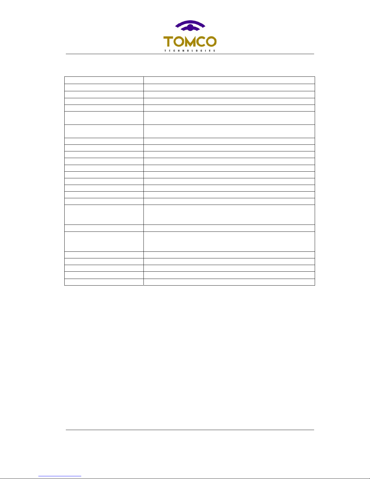
SPECIFICATIONS
Rated Output Power 250W (50Ωload) minimum for 0dBm drive
CW Mode Output Power 50W CW (50Ωload) maximum continous power
Power@1dB compression 200W (50Ωload) minimum
Frequency 0.1-30MHz (Alpha-S)
Gain Flatness +/- 2.0dB max.
Maximum duty cycle (pulsed
mode) 20% continuous
Max.pulse width (pulsed
mode) 100ms
Pulse droop <0.5dB @ max.pulse width (requires external storage capacitor)
Harmonics <-20dBc even, -12dBc odd at 1dB compression power
Spurious <-70dBC
Rise/fall times <100ns typical (pre-gated)
Output noise (blanked) <10dB above thermal (1MHz bandwidth)
Noise figure Approx.10dB
Phase stability 5° max change over a 1ms pulse
Phase change/power 5° max.change from -30dB to full power
Phase stability/time <1° max.change in 24hrs
Input VSWR 2:1 max.
Load VSWR Approx 2.5:1 max. without external protection.
The module does not incorporate protection against poor load
VSWR.
Gate input 0-5V, 1.0kΩ
Connectors RF output: 50 ohm SMA
RF drive: SMA
Gate: SMA
Dimensions 200x120x65mm
Mass 2kg
Cooling Forced air required
Operating Temperature 0°C - 40°C (maximum allowable case temperature 80°C)
Humidity 95% non-condensing
Table of contents
Popular Amplifier manuals by other brands


Mesa/Boogie
Mesa/Boogie Heartbreaker owner's manual

NuWaves
NuWaves NUPOWER 12B01A-02 user manual

Kramer
Kramer TOOLS VP-210XL user manual

Factor Electronics
Factor Electronics AM-160 quick start guide

Key Digital
Key Digital Phantom KD-HD1x4ProK operating instructions

Carson
Carson SA-441-17 Installation & operating instructions


