Tone T-3 User manual

T-3 Build Guide
*All product names, trademarks and registered trademarks are property of their respective owners.

Page 2
While many of these procedures are applicable to the T-1
and T-1 Mini jets as well, this guide is specific to the T-3 With Electric Gear Set.
This guide does not cover radio setup, programming or turbine operation. You will
need to refer to the documentation provided with those systems for information on
proper setup and operation.
T-3 ARF Kit:
•Fuselage; Forward, Center, AFT
•Rudder and Stab (Factory Hinged)
•Wings, Factory Hinged Ailerons with Flaps
•Landing Gear with struts and brakes (Electric Comes with Gear and Brake Controller)
•Complete Hardware Package
•Linkage and ball links
•Dual Walled Pipe
•Kevlar Fuel Tank/Smoke Tank Combo with Hysol in fittings
Tips for Success:
•Don’t rush! Allow plenty of time for your build. Take your time, enjoy it, and do it right.
•Don’t be afraid to ask questions! In addition to this document there are several build threads on RC Universe
where you can get input and assistance with your build:
•Complete the latter part of your build on a CG stand…when you’re down to the components that can relocate in
order to adjust CG.
•After your build is complete, have another turbine operator/pilot review your build. A fresh set of THIS s is a
good sanity check.
Specifications:
•Length: 118”
•Wing Span: 103”
•Fuel Tank 256oz
•Smoke Tank 60ozDry Weight 45-48Lbs
•Recommended Engine 180-260
•Center of Gravity: 335mm - 345mm from leading edge of wing root.
•Recommended Aileron Throw: 18-20mm
•Recommended Elevator Throw: 20-25mm
•Recommended Rudder Throw: 25mm
•Recommended Flap Throw: Half flaps = 35mm, Full flaps = 65mm
•Recommended Flap Throw: Half flaps = 45mm, Full flaps = 70mm

Page 3
The kit will come very well packed.
Carefully remove all the parts from the
bubble wrap that they are encased in. Do
not use a knife or razor as you can
inadvertently cut through the packaging
and damage the finish of the parts. Peel or
use scissors to carefully cut and remove
the tape.
Inspect all parts for any shipping damage
and test fit. Check all packaging, parts and
components. It’s good to organize and
identify hardware and components before
you start the build.
You can use some of the packaging
material to place your air-frame parts on to
keep from damaging or scratching during
your build.
Sometimes the painting process results in a
rough edge that might cause binding. This
is easily resolved by using a common emery
board to gently smooth the
underside/inside the flight surface and the
top/outside on the control surface. Use
tape to protect the painted areas on
control surfaces. Go slow and don’t be too
aggressive with the file to avoid removing
too much material.
Equipment Used (Sold Separately)
•Spektrum radio System
•Demon Cortex Gyro
•KingTech K210G2
•KingTech 2X 6.6 3800 Life Packs
•KingTech 9.9 3800 Life Pack
•KingTech 150cc UAT with Holder
•KingTech Smoke Pump
•PRCJ 6mm Poly Fuel Tubing (6 Feet)
•PRCJ XXL 36” Smoke Tube
•PRCJ Large Vents with caps
•PRCJ T-3 E-Gear Wire Harness (PJ-
T3WHRB)
•PRCJ T-3 (8) Pack Savox SA1230SG
•PRCJ Advanced CG Stand

Page 4
AFT Fuselage Zip Tie Mounts & Harness
Installation.
For this process we use self-adhesive Zip
Tie mounts and small Zip Ties to secure the
wire harness in place. Use the photos for
reference on where to install the Zip Tie
mounts and harness. Note: Start wire
harness installation from the AFT forward
leaving at least 2” of wire out of the
fuselage at the connection points for the
stab and rudder.
Once wires are secure use CA or Hysol on
edges of Zip Tie mounts for permanent
adhesion.
Make sure to have no sagging wires. You
can use aluminum tape around
Midbody Fuselage Zip Tie Mount
Installation.
For this process we used the self-adhesive
Zip Tie mounts. Use photos for reference
on where to install the Zip Tie mounts. Use
CA or Hysol on edges of Zip Tie mounts for
permanent adhesion.

Page 5
Midbody & AFT Fuselage Assembly.
Make sure the bell mouth is secure and
tight to the pipe. If you plan to use the
PRCJ 36” Smoke Stick, pre-install now at
the top center of the pipe and slide pipe
into AFT Fuselage. Pull your wires through
at the top access area, line up the
AFT/Midbody sections, apply Blue Medium
Thread Locker and install top bolt with the
provided wrench, (Lightly Tighten Bolt)
then loose install the remaining 5 bolts
with Medium Thread Locker. During
tightening, ensure proper alignment of the
AFT and Midbody sections before fully
tightening down the bolts
Securing Pipe and Smoke Tube.
Install the pipe mounting “L” tabs at the
center line of the pipe and secure with
provided hardware, see Photo for
reference. Using your turbine for mock-up,
set the distance and pipe alignment. The
end of the pipe should be flush with the
rear section of the jet as shown in photo.
Once alignment is achieved secure pipe
with provided screws as shown in photo.
Bring smoke tube end out of the rear of the
pipe about 1.5 inches and bend down to
get into the hot exhaust stream. Adjust
rotation of smoke tube and then bend at
the bellmouth area as needed. We used Zip
Ties and mounts to secure smoke tubing.
Wire tie and run smoke tubing forward to
tray.

Page 6
Engine to Pipe Spacing and Installation.
This is a crucial part of any engine
installation. Please refer to your engine
documentation for proper installation and
engine to pipe spacing practices. The
photos show a proper reference for engine
spacing and alignment.
You should have 1” spacing between the
end of the engine tailcone and the
beginning of the pipe inlet
(NOT THE BELL MOUTH)
The tailcone of the engine should be tucked
inside the bellmouth. Once center
alignment and distance is achieved, you
can drill/mount your engine using wood
style screws or bolts with blind/lock nuts.
Fuel Tank Assembly and Installation.
Pre-fit and dry install your fuel tank fittings,
you will drill can vent holes where needed.
NOTE: when locating the vent hole for the
fuel tank, be sure to pay attention to where
the split line is. You must be under the
tank/smoke tank separation line; you can
see inside the main tank for reference.
Carefully clean and Hysol in fittings. Note
fitting directions. Build tank clunk pick-up’s
as seen in photos. Be sure to solder collets
to both ends of the brass tubing. Measure
lengths of tubing as needed and pre-fit
after curing of fittings. Use wire tie to
secure fuel tubing. Pre-drill aluminum
mounting tabs before installing into
Midbody. Use provided wood screws to
install tank. We recommend a bead of
silicone around the front edge of the tank
to the fuel tray for added security.
Tank must be installed in Midbody
before nose section installation!

Page 7
Midbody & Nose Section Assembly.
After the nose gear installation is
completed, line up the Nose/Midbody
sections, apply Medium Thread Locker and
install top 2 bolts with the provided
wrench. (Lightly Tighten Bolts) then loose
install the remaining 5 bolts using Medium
Thread Locker and provided wrench.
Ensure proper alignment of the Nose and
Midbody sections and test canopy fitment
before fully tightening down the bolts. You
can use a straight edge across the fuselage
canopy edge surface to help with
alignment as well. You can use the Zip Tie
mounts to rout gear, steering and door
servo wires to the main tray area on the
right or left side of the nose gear
depending on your install.
TANK MUST BE IN MIDBODY BEFORE PROCEEDING!
Electric Nose Gear Installation.
Locate the nose gear steering horn and
install into strut using Medium Thread
Locker.
Install the steering servo using the
hardware that came with your servo to
mount onto the steering servo plate. Use
Medium Thread Locker
Center up your servo using a servo
centering device, adjust and install the
linkage as shown in photo.
Test fit the nose gear in the nose gear bay.
Verify that there is clearance between all
moving parts in the area such as the gear
door servo, arm, pushrod, and gear door
hinges. Mark hole locations and us a small
pilot drill for the holes then bolt gear into
place.

Page 8
Electric Main Gear Installation.
Feed the main gear and brake wires to the
access area and plug into the wing wire
harness. (Always secure wire connections)
Slide the retract into place and locate the
strut, wheel and brake in the wheel well
making sure that you have equal distances
all the way around the tire and strut as
seen in photo.
When proper location is achieved, mark
holes and drill pilot holes, NOTE: Use a drill
stop to set drill depths as to not accidently
drill through wing. Use the (4) provided
screws to mount gear in place. Install gear
cover using provided hardware, slight
trimming may be required for fitment. Use
Aluminum tape to secure brake wires.
Electric Gear Controller Setup.
Each of the three gear units is
independently programmable.
• Long press the mode button to enter
programming mode.
• Short press the mode button to cycle
through the programming options below.
• When the A or B light is blinking, you can
press the + or –button to change the servo
direction. This setting is used if the door is
open when it should be closed or vice
versa.
• When the A and B lights are alternating,
pressing the + or –will increase or
decrease the servo throw on one end of its
movement. This setting is so that you can
adjust the door to open or close all of the
way without excessive binding at the
extents of motion.

Page 9
Electric Gear Controller Setup Continued.
• When the C and D lights are alternating,
pressing the + or –will increase or
decrease the servo throw on one end of its
movement. This setting is so that you can
adjust the door to open or close all of the
way without excessive binding at the
extents of motion.
• The C light blinking alone indicates Mode
1 operation for that gear unit.
• The D light blinking alone indicates Mode
2 operation for that gear unit.
• When you have completed making your
programming adjustments, long press the
mode button to save your changes and exit
programming mode.
Electric Brake Controller Setup.
Connect the two-wire break leads from the
main gear to the “Brake output” port on
the side of the brake controller. Connect
the radio lead from the brake controller to
the appropriate channel that you have
configured for brake operation. Lastly,
connect the power lead to your power
source (7.4V-25.2V). Turn the strength
screw adjustments to their weakest setting
(completely clockwise). You will need to
execute some taxi and brake tests at your
flying location to tune the brake strength
and radio settings that will work best for
you. Ensure that you have your brakes and
landing gear tuned and working prior to
any flight operations.

Page 10
Air Gear Installation.
This is a basic air system setup with a gear
fail safe, dual air valves for gear and door
operations. Brakes system is also a basic
brake control setup. All components
available at www.pacificrcjets.com
Air Gear Installation Photos.
Adhere the two air tanks under the main
board in front of the bulkhead. Use the Zip
Tie mounts to secure your air lines in place.
T off at the center of the fuselage where
the airline to wing area is, use the provided
air line connections and be sure to
bring air lines out minimum 2”
Fuel System Installation
There are different ways to rout your fuel
lines and other location to mount your
UAT, refer to the drawings on the right for
fuel system plumbing along with your
turbine manual. We recommend the PRCJ
Polyurethane tubing and always wire tie
for safety. We also recommend the
Kingtech UAT with PRCJ UAT mount and
ball valve mount.

Page 11
Stab servos Installation
Locate the hardware and servo L brackets.
Mock-up and install the L brackets on the
servo as needed to archive proper
direction and (Best Center) position in the
servo pocket. Use medium Thread locker to
secure.
Plug in your servo extension and use heat
shrink or other methods to secure
connection
Build your servo linkage using 1.0” servo
horns. Use provided ball links and
hardware with threaded control rod. Use
the 35mm threaded rods for Elevators
Center up your servo using a servo
centering device and install servo horn
Locate and install servos using the provided
(SHORT WOOD SCREWS)
Adjust and attach to elevator control horn
and adjust radio as needed to achieve
control throws.
After control setup is complete, remove
ball link from servo horn and install servo
cover using the provided wood screw
Re-attach ball link to control horn and re-
test control throws
Page 12
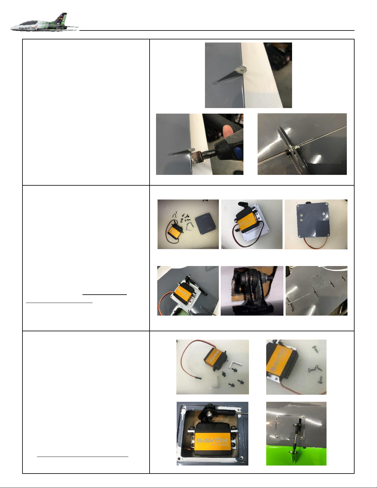
Flaps and Flap servos Installation
Carefully remove the paint from the hinge
on the wing side. This will allow free
smooth movement of the flaps and
eliminate any binding and or sticking.
Use the supplied lock nuts, bolts and
washers to install flaps.
Check for smooth movement after
installation of flaps.
Flaps and Flap servos Installation
Locate the hardware and servo L brackets.
Mock-up and install the L brackets on the
servo as needed to archive proper
direction and use medium Thread locker.
Use the provided counter sunk machine
screws to attach the servo to the flap servo
cover and use medium Thread locker.
Center up your servo using a servo
centering device. Build linkage using a
shorter ½ servo arm with the provided ball
ends, hardware and 35mm threaded
control rod for the Flaps Adjust and attach
to flap control horn and adjust radio as
needed to achieve max travel.
Repeat process For Other Side
Aileron servos Installation
Locate the hardware and servo L brackets.
Mock-up and install the L brackets on the
servo as needed to archive proper
direction and (Best Center) position in the
servo pocket. Use medium Thread locker to
secure.
Center up your servo using a servo
centering device. Build your servo linkage
using a 1.0” servo arm. Locate and install
servo using the provided (SHORT WOOD
SCREWS) Use provided ball links and
hardware with threaded control rod. Use
the 45mm threaded rods for Ailerons
Repeat process For Other Side

Page 13
Rudder servo Installation
Locate the hardware and servo L brackets.
Mock-up and install the L brackets on the
servo as needed to archive proper
direction and (Best Center) position in the
servo pocket. Use medium Thread locker to
secure.
Center up your servo using a servo
centering device. Build your servo linkage
using 1.0” servo horns. Locate and install
servo using the provided (SHORT WOOD
SCREWS) Use provided ball links and
hardware with threaded control rod. Use
the 85mm threaded rods for Rudder
Adjust and attach to Rudder control horn
and adjust radio as needed to achieve
control throws.
After control setup is complete, remove
ball link from servo horn and install servo
cover using the provided wood screw.
Re-attach ball link to control horn and re-
test control throws.
Final Component installation Photos
These photos show our basic installation of
components. There are many ways to lay
out and setup your T-3 electronics.
Pacific RC Jets offer many great solutions
for RX, Gear/Brake controllers, Smoke
pumps, Gyros, batteries, wing bags and
other products.
We appreciate your business.
www.pacificrcjets.com
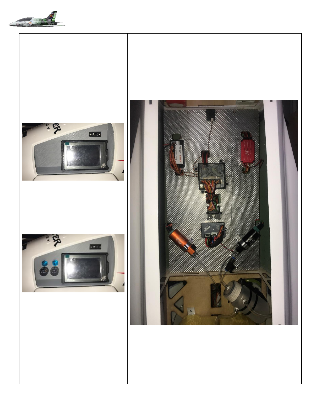
Page 14
Final Component installation Photos
With Electric Retracts
With Air Retracts

Page 15
Congratulations! You have completed the
assembly and configuration of your T-3
turbine sport jet!
Make sure you have another set of eyes give
your aircraft a good looking-over. Quite
often, a problem can be spotted by a fresh,
experienced pair of eyes. It’s better to find
and fix rather than fly and fail.
FLY SAFE AND HAVE FUN!!!
Document:
Version 1.0 –Jan 2019 –Initial composition and release.
Table of contents
Other Tone Toy manuals

Popular Toy manuals by other brands


Tamiya
Tamiya M4 Sherman manual

Faller
Faller 120482 instructions

Black Horse Model
Black Horse Model MIDGET MUSTANG-EP Instruction manual book

Sutcliffe Play
Sutcliffe Play Ladybird Springie SSB160 installation instructions

Mattel
Mattel Hot Wheels Slot Car Racing G4186 quick start guide

Hasbro
Hasbro Transformers Universe Autobot Roadbuster 83794... installation guide