Tonghui Electronics TH7105 User manual


TH7100 Operation Manual
Contents
Contents
Chapter 1 Introduction.............................................................................................................. 1
1.1 Introduction of the Instrument .......................................................................... 1
1.2 Working Condition.............................................................................................. 2
1.2.1 Power Connection.......................................................................................... 2
1.2.2 Environment Temperature and humidity........................................................... 2
1.2.3 Precautions for usage ......................................................................................... 2
1.2.4 Warm-up............................................................................................................. 3
1.3 Safety and Symbols............................................................................................. 3
1.3.1 Signs and Symbols .............................................................................................. 3
1.3.2 Laws and regulations .......................................................................................... 4
Chapter 2 Introduction.............................................................................................................. 5
2.1 Introduction to Front Panel ................................................................................ 5
2.2 Introduction to Rear Panel ................................................................................. 5
2.3 Display Zoon ....................................................................................................... 6
2.4 Basic Operation .................................................................................................. 7
2.4.1 Manual mode ..................................................................................................... 7
2.4.1 Programmable Mode.......................................................................................... 8
2.5 Boot Instructions ................................................................................................ 8
Chapter 3 Basic Operations and Description........................................................................... 10
3.1 <Measurement Display>................................................................................... 10
3.1.1 Pending measurement status........................................................................... 10
3.1.2 Test Status Instruction...................................................................................... 15
3.2 <MANU SETUP> ................................................................................................ 17
3.2.1 Memory Setting................................................................................................ 17
3.2.2 Common Setting ............................................................................................... 20
3.3 <Programmable Mode>.................................................................................... 24
3.3.1 Sequence Setting .............................................................................................. 24
3.3.2 Common Setting ............................................................................................... 33
3.4 <System Setting> .............................................................................................. 37

TH7100 Operation Manual
Contents
3.4.1 System Environment......................................................................................... 37
3.4.2 System Communication.................................................................................... 39
3.4.3 System Tool ...................................................................................................... 41
Chapter 4 File Management.................................................................................................... 43
4.1 Internal File....................................................................................................... 43
4.1.1 Description........................................................................................................ 43
4.1.2 Operation.......................................................................................................... 43
4.2 External File ...................................................................................................... 44
4.2.1 Description........................................................................................................ 44
4.2.2 Operation.......................................................................................................... 45
Chapter 5 Function Introduction............................................................................................. 47
5.1 Function Structure Introduction....................................................................... 47
5.2 Programmable Mode Output Function ............................................................ 48
5.3 Surge Drop Function......................................................................................... 50
5.4 Dimmer Mode Function ................................................................................... 52
5.5 Result Display Function .................................................................................... 53
5.6 Protection Function .......................................................................................... 55
5.7 Remote Signal Output Function ....................................................................... 56
5.8 Remote Control Function ................................................................................. 57
Chapter 6 Communication Interface....................................................................................... 59
6.1 RS232 Interface................................................................................................. 59
6.1.1 Description........................................................................................................ 59
6.1.2 Operation.......................................................................................................... 60
6.2 USB Virtual Serial Port ...................................................................................... 61
6.2.1 Description........................................................................................................ 61
6.2.2 Driver Installation ............................................................................................. 61
6.3 SCPI Communication Commands ..................................................................... 62
6.3.1 Command Types ............................................................................................... 62
6.3.2 Command Syntax.............................................................................................. 63
6.3.3 Common Commands ........................................................................................ 65

TH7100 Operation Manual
Contents
6.3.4 DISPlay Subsystem Commands......................................................................... 66
6.3.5 :FUNCtion Subsystem Commands .................................................................... 67
6.3.6 FETCH Subsystem Commands .......................................................................... 89
6.3.7 SYStem Subsystem Commands ........................................................................ 91
6.4 MODBUS Communication Commands ............................................................. 97
6.4.1 MODBUS Protocol ............................................................................................ 97
6.4.2 MODBUS Write Commands.............................................................................. 99
6.4.3 MODBUS Read Commands............................................................................. 131
Chapter 7 Technical Specifications........................................................................................ 166
7.1 Product Specifications .................................................................................... 166
7.1.1 AC Input .......................................................................................................... 166
7.1.2 AC Output ....................................................................................................... 166
7.1.3 Setup............................................................................................................... 166
7.1.4 Measurement ................................................................................................. 167
7.1.5 Convention ..................................................................................................... 167
7.1.6 Dimension....................................................................................................... 168
7.2 Supplementary features................................................................................. 168
Chapter 8 Warranty............................................................................................................... 169
Chapter 9 Appendix............................................................................................................... 170
9.1 Error Message................................................................................................. 170
9.2 SCPI Commands.............................................................................................. 170
9.2.1 DISP Commands.............................................................................................. 170
9.2.2 FUNC Commands............................................................................................ 171
9.2.3 SYST Commands ............................................................................................. 177
9.2.4 FETCH Commands........................................................................................... 178
9.3 MODBUS Commands...................................................................................... 178
9.4 Manual Amendment Description ................................................................... 182

TH7100 Operation Manual
Contents
Declaration
The descriptions contained in this manual may not cover all information about this instrument.
Introductions to the improvements of the instrument in performance, function, internal structure,
outer appearance, accessories, packing material, etc. are subject to change without notice. If you
find any inconformity of this manual with our instruments, please contact us for further
consultation by the address listed on the cover.

1
Chapter 1 Introduction
Thank you for purchasing and using of our products. If you have questions after reading this manual, please
contact your local distributor or call our company's engineers directly for further consultation.
1.1 Introduction of the Instrument
TH7100 series is a family of single-phased programmable AC power supply which is able to simulate a variety
of normal and abnormal AC input conditions, and do the measurement of some important parameters. The main
features and benefits of the instrument are listed below:
24-bit color, 4.3-inch LCD display
Chinese and English operating interface
Support output switch control
Voltage (V), Current (I), Power (P), Peak Current (Ap), Crest Factor (CF), and Power Factor (PF) can be
displayed simultaneously
Starting phase angle (0~359°), ending phase angle (0~359°)
Support surge/drop, and dimming mode function
Support front and rear panel output
Memory capacity
Manual mode: 50 sets
Programmable mode: 50 sets, 9 steps/set
Intelligent temperature-controlled fan, two stages fan speed
Start up with user’s setting
Support timing function
Support RS232 (SCPI and MODBUS protocol), and USB COM.
Support remote signal output function (PASS、FAIL、PROCESSING)
Support remote control input function (includes output switch and input control of 7 memory groups)
Support over setting current protection (HI-A), over voltage protection (OVP), low-voltage protection
(LVP), over current protection (OCP), over power protection (OPP), over temperature protection (OTP)
Th7100 series single-phase programmable AC power supply includes the following models:
Model
Voltage
Current
Power
TH7105
300V
4.2A
500W
TH7110
300V
8.4A
1000W
TH7120
300V
16.8A
2000W
Table 1-1 Main Parameters of Various Models
2
1.2 Working Condition
1.2.1 Power Connection
1) Power supply: 100~120Vac or 198~242Vac
2) Power supply frequencies: 47~63Hz
3) Power range: ≥80VA
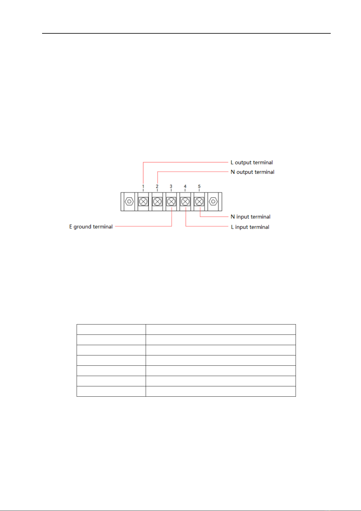
4) The power input line L, zero-line N and ground-line E should be the same as the power plug of this
instrument. Remove the protection cover on the rear panel before use of the instrument, the detailed
wire connection diagram is shown in figure 1-1:
Figure 1-1
1.2.2 Environment Temperature and humidity
TH7100 series programmable AC power supply is only allowed to be used indoors and in low-condensation
areas. The general environmental requirements of this instrument are shown in table 1-2. The fan speed changes
intelligently with the radiator temperature. When the radiator temperature reaches 60°C, the fan accelerates.
When the radiator temperature reaches 130°C, the instrument shuts off the output.
Environment Condition
Requirements
Operating Temperature
0℃~40℃
Operating Humidity
20%~80%(non-condensation)
Storage Temperature
-20°C~70°C
Operating Altitude
≤2000m
Pollution
Pollution level2
Safety
Safety class II
Figure 1-2
1.2.3 Precautions for usage
1) Please do not use the tester in dusty, vibrative, direct sunlight and corrosive gases and other adverse
environments.

3
2) Please do not use damaged equipment. Before use of the instrument, please check if there are any
cracks on the shell.
3) Please connect the device with the provided cable. Before operating the instrument, make sure theAC
power supply is well grounded.
4) Before connecting to the device, check all the security labels on the device.
5) Please use wire with rated load. The capacity of all load wires must be able to withstand the maximum
short-circuit output current of the power supply without overheating. If there are multiple loads, each
pair of load wires must be able to safely carry the full load rated short-circuit output current of the
power supply.
6) Please do not install replacement parts or make any unauthorized modification of the instrument.
7) Please do not use the device when the cover is removed or loose.
8) It is strictly prohibited to use this instrument on life support system or any other equipment with safety
requirements.
9) Keep the instrument well ventilated to avoid overheating. Do not block the ventilation hole of the
equipment to avoid internal temperature rising affecting the accuracy.
10) Please use dry cloth to clean the shell of the equipment. Do not clean the inside of the instrument.
11) Please do not switch the instrument frequently to avoid loss of stored data.
12) The instrument has been carefully designed to reduce clutter due to AC power input. However, it
should still be used under low noise conditions. If that is inevitable, please install the power filter.
13) When the instrument is not used for a long time, please put it in the original box or similar box and
stored in a ventilated room with temperature of 5℃~40℃and relative humidity less than 85% RH.
Do not store the instrument in a corrosive atmosphere containing harmful impurities and should avoid
direct sunlight.
1.2.4 Warm-up
For accurate measurement, the warm-up time should not be less than 30 minutes.
1.3 Safety and Symbols
1.3.1 Signs and Symbols
ON ( power switch closed)
Protective grounding terminal
OFF (power switch open)
Ground terminal
Warning sign
Power line ground
4
Shock hazard sign
Table 1-3
1.3.2 Laws and regulations
CE label indicates that the instrument complies with all relevant European laws (a year indicates the
year in which the design was approved).
This device complies with the marking requirements of WEEE directive (2002/96/EC), and this
additional product label states that this appliance/electronic product should not be discarded in household waste.
According to the WEEE directive annex I classification of the equipment, the instrument belongs to “monitor”
products.
5
Chapter 2 Introduction
The content of this chapter is just a general description. It mainly introduces the front and rear panel, display
area, boot interface and basic operation. Please refer to chapter 3 for detailed introduction.
2.1 Introduction to Front Panel
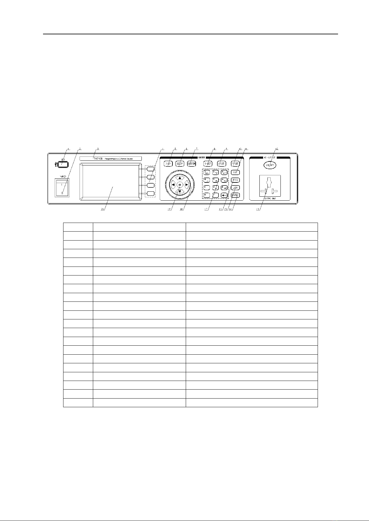
TH7100 series programmable AC power supply front panel is shown in figure 2-1.
Figure 2-1 Front panel
Index
Name
Function
1
U disc interface
Read or store data
2
Power switch
Power switch
3
Trademark and models
Instrument trademark and models
4
Function buttons
Screen-labeled function keys
5
DISP
Quickly switch to measurement display page
6
SETUP
Quickly switch to measurement setting page
7
SYSTEM
Quickly switch to system setting page
8
V-SET
Voltage setting
9
I-SET
Current setting
10
F-SET
Frequency setting
11
ESC
Exit or cancel
12
ON/OFF
Output switch
13
Power Output Socket
Power output Socket
14
ENTER
Enter button
15
LOCK
Keyboard lock button
16
TRIG
Surge/drop manual trigger button
17
Number pad and delete button
Number input and delete
18
knob
Adjust the setting value or move the cursor
19
Arrow key and OK button
Move the cursor and enter
20
LCD display
Screen display
2.2 Introduction to Rear Panel
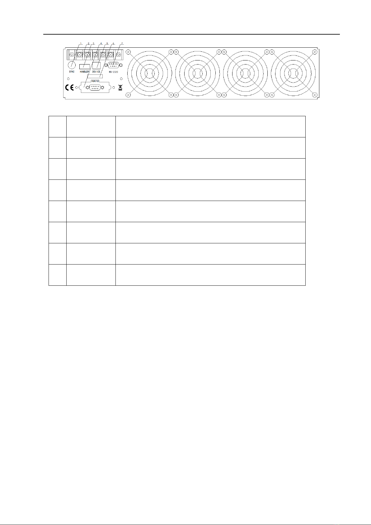
TH7100 series programmable AC power supply rear panel is shown in figure 2-2.
6
Figure 2-2
Index
Name
Function
1
Synchronism
Signal Socket
When output is enabled, it will output a 10V voltage signal from the
socket at the same time.
2
Power Input
Output
Terminal
Power terminal and power output terminal
3
Signal Output
Terminal
Output signals of PASS, FAIL, and PROCESSING for automation
devices.
4
Remote Control
interface
Control output switches, and choose to execute memory groups M1,
M2 to M7.
5
USB COM
Interface
Through this port, TH7100 series instrument can be controlled by
external controller, and realize online communication with computer
6
Nameplate
Production date, instrument number, manufacturer.
7
RS232 Serial
Interface
RS232 serial communication interface, used for online
communication with computer.
2.3 Display Zoon
The TH7100 series programmable ac power supply has a 24-bit color 4.3-inch color LCD screen with a
resolution of 480×272. The content displayed on the screen is shown in figure 2-3.
7
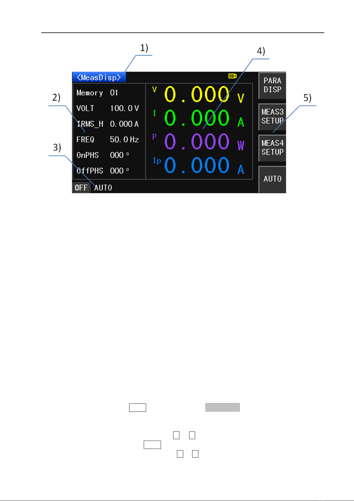
Figure 2-3 display description
1) Main menu zone
This area indicates the name of the current page
2) Parameters setup zone
This area is used to modify the test parameters
3) Status zone
This area is used to display various prompt information and various status information during system testing.
4) Measurement result display zone
This area shows the parameter results of the test. The parameter display 1 indicates the output voltage value,
the parameter display 2 indicates the output current value, the parameter display 3 indicates the output power
value, and the parameter display 4 indicates the peak current value.
5) Soft key zone
This area is used to display the function menu corresponding to the cursor area.
2.4 Basic Operation
2.4.1 Manual mode
1) Set the output mode: Press the SETUP button, then press the MANU SETUP function button.
2) Set the voltage output mode: Make use of the direction key to move the cursor to the V mode, and then use
the soft key to select AUTO or HIGH voltage.
3) Set the output voltage: Press the direction key or to move the cursor to VOLT setting, and set the
output voltage by the numeric keys and ENTER key.
4) Set the output frequency: Press the direction key or to move the cursor to FREQ setting, and set the

8
output frequency by the numeric keys and ENTER key.
5) Test output: Press the DISP button, then press the ON/OFF button to output.
2.4.1 Programmable Mode
1) Set the output mode: press the SETUP key, then press the PROG SETUP function key
2) Set the sequence setting parameters: Press the direction keyor to move the cursor to set the
parameters such as set voltage, voltage mode, frequency, step connection, delay time, dwell time and so on.
3) Setting steps: Press the arrow keysor to move the cursor to the parameter step. Use the numeric keys
and the ENTER key to set the step number, then follow step 2) to set the parameters under the step number.
4) Repeat steps 2) and 3) to set the required steps.
5) Test output: Press the DISP button, then press the ON/OFF button to output.
2.5 Boot Instructions
Press the power switch in the lower left corner of the front panel of the instrument to turn the instrument on
and display the boot screen. Figure 2-4 shows the boot screen of the TH7100 series programmable AC power
supply. The boot screen includes some product information such as the trademark, instrument model and
software version number of Tonghui Company.
Figure 2-4 Start Up Screen
If the user has turned on the password protection function, then the instrument will request to enter the
power-on password. Enter the power-on password according to the screen display. This series of products is
not set with the power-on password when leaving the factory, users can reset the power-on password
according to their needs during use. For details, see Password on the <System Settings> page.

9

10
Chapter 3 Basic Operations and Description
This chapter mainly introduces the description and operation of the setting parameters under the
<Measurement Display> page, the description and operation of the soft key area buttons, and the description
of the status area; Description and operation of setting parameters under <Manual mode> page; Description
and operation of setting parameters under <Programmable mode> page; Description and operation of
parameters under <System setting> page; Description and operation under <Internal file>, <External file> page.
3.1 <Measurement Display>
3.1.1 Pending measurement status
Press the DISP menu button, when the test mode is manual mode, the <Measurement Display> page is shown
in Figure 3-1:
Figure 3-1 Manual mode <measurement display> page
When the test mode is programmable, the <Measurement Display> page is shown in Figure 3-2:
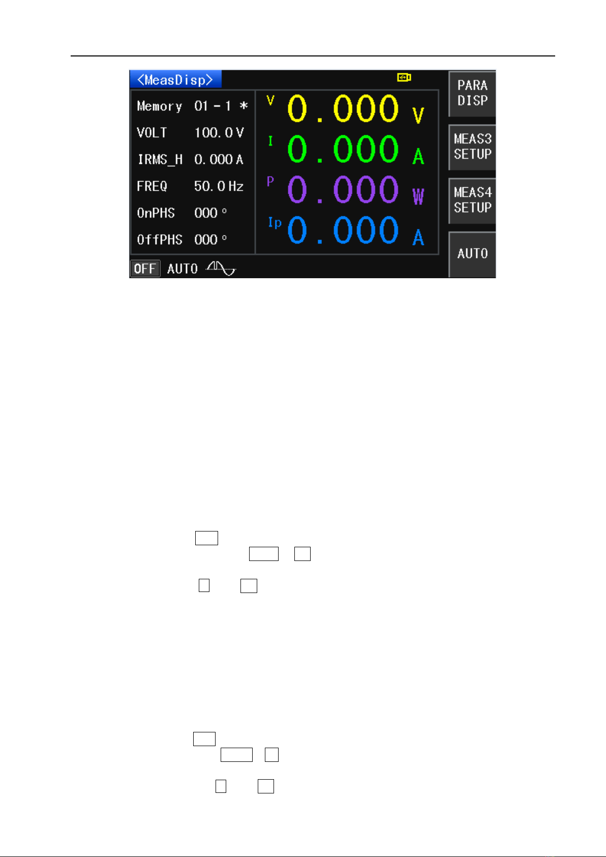
11
Figure 3-2 Programmable Mode <Measurement Display> page
3.1.1.1 Parameter setting description and operation
Memory
1) Description
In manual mode, this parameter value indicates memory group number, and there are 1~50 memory
groups in total. In the programmable mode, the first number indicates the memory group number,
and there are 1~50 memory groups in total; The second value indicates the step number, a total of 1
to 9 steps. The * after the value indicates that the step connection is turned on. If there is no * after
this value, the step connection is turned off.
2) Operation
Press the key or knob to move the cursor to this parameter option, change the value via the front
panel numeric keys, then press ENTER or OK to confirm. When changing the value with the numeric
keys, if you do not want to change the parameter value or press the wrong numeric key, you can
cancel it by pressing key or ESC key.
Voltage (VOLT)
1)Description
This parameter represents the output voltage setting, and the voltage setting range is 0.0~300.0V. In
manual mode, this parameter can be quickly changed by V-SET button. In programmable mode
measurement display page, this parameter cannot be changed.
2)Operation
Press the key or knob to move the cursor to this parameter option, change the value by front panel
numeric keys, then press ENTER or OK button to confirm. When changing the value with the numeric
keys, if you do not want to change the parameter value or press the wrong numeric key, you can
cancel it by pressing the key or ESC key.

12
Current (IRMS_H)
1)Description
This parameter represents the current upper limit setting. When the setting voltage is not greater than
150V, the range is 0.000~8.400A; When the setting voltage is greater than 150V, the setting range is
0.000~4.200A. When set to 0.000, the current upper limit function is turned off. In manual mode, this
parameter can be changed quickly by I-SET button. This parameter cannot be changed under the
programmable mode measurement display page.
2)Operation
Press thekey or knob to move the cursor to this parameter option, change the value via the front
panel numeric keys, then press ENTER or OK to confirm. When changing the value with the numeric
keys, if you do not want to change the parameter value or press the wrong numeric key, you can
cancel it by pressing the key or ESC key.
Frequency (FREQ)
1)Description
This parameter represents the output frequency setting, and its setting range is 45.0~500Hz. In
manual mode, this parameter can be changed quickly by F-SET button. This parameter cannot be
changed under the programmable mode measurement display page.
2)Operation
Press thekey or knob to move the cursor to this parameter option, change the value via the front
panel numeric keys, then press ENTER or OK to confirm. When changing the value with the numeric
keys, if you do not want to change the parameter value or press the wrong number key, you can cancel
it by pressing the key or ESC key.
Initial Phase Angle (ONPHS)
1)Description
This parameter represents the initial phase angle of the output waveform and ranges from 0 to 359°.
This parameter cannot be changed under the programmable mode measurement display page.
2)Operation
Press the key or knob to move the cursor to this parameter option, change the value via the front
panel numeric keys, then press ENTER or OK to confirm. When changing the value with the numeric
keys, if you do not want to change the parameter value or press the wrong numeric key, you can
cancel it by pressing the key or ESC key.
Ending Phase Angle(OFFPHS)
1)Description
This parameter represents the ending phase angle of the output waveform, which ranges from 0 to
359°. This parameter cannot be changed under the programmable mode measurement display page.
13
2)Operation
Press the key or knob to move the cursor to this parameter option, change the value via the front
panel numeric keys, then press ENTER or OK to confirm. When changing the value with the numeric
keys, if you do not want to change the parameter value or press the wrong numeric key, you can
cancel it by pressing the key or ESC key.
3.1.1.2 Soft keypad description and operation
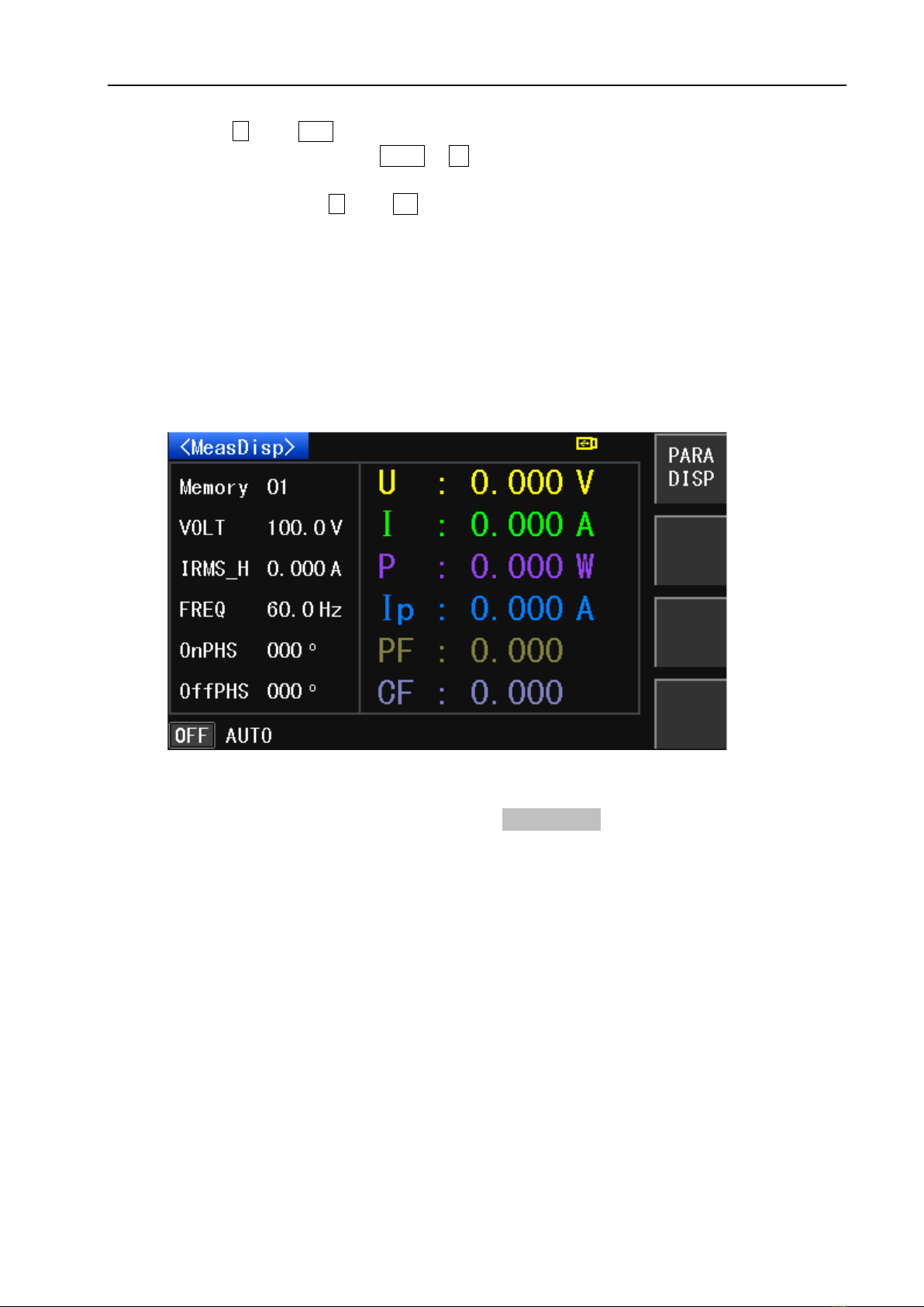
Parameter Display (PARA DISP)
1)Description
This softkey is used to switch the output parameter display. As shown in Figure 3-3:
Figure 3-3
2)Operation
Under the <Measurement Display> page, press the Display Switch button of the soft key area to switch
the output parameter display.
MESA3 SETUP
1)Description
This soft-key is used to configure the parameters required for MESA3, press this soft-key to select the
power (PWR)、peak current (APK)、power factor (PF)、crest factor (CF). Please refer to figure
3-4

14
Figure 3-4 MESA3 Key
2)Operation
Under the <Measurement Display> page, press the MESA3 key of the soft key area, then press the
PWR or APK or PF or CF as needed to switch output parameters of MESA 3.
MESA4 SETUP
1)Description
This soft-key is used to configure the parameters required for MESA4, press this soft-key to select the
power (PWR)、peak current (APK)、power factor (PF)、crest factor (CF). Please refer to figure
3-5.
Figure 3-5 MESA4 Key
2)Operation
Press the key or knob to move the cursor to this parameter option, the soft-key zone displays the
function menu for this parameter, which can be changed by turning the soft-key ON or OFF.
AUTO

15
1)Description
This key is the voltage mode setting key, which can be set to “AUTO” or “HIGH”. When the voltage
mode is set to “AUTO”, it will automatically judge whether the voltage is high or low based on the
setting voltage. When the voltage mode is set to “HIGH”, the voltage will be set to HIGH (i.e. the range
of 0~300V).
2)Operation
In <Measurement Display> page, press AUTO soft key to switch between “AUTO” and “HIGH”.
3.1.1.3 State Zoon Description
OFF: Output is not enabled
AUTO: Voltage mode is in “AUTO”
: Surge/drop function is enabled
3.1.2 Test Status Instruction
In <MeasDisp> page, press ON/OFF button to enable output. When the test mode is in MANU SETUP mode,
the <MeasDisp> page is shown in figure 3-6:
Figure 3-6 MANU SETUP Mode <MeasDisp> Page
When the test mode is in PROG SETUP, the <MeasDisp> page is shown in figure 3-7:
This manual suits for next models
2
Table of contents


