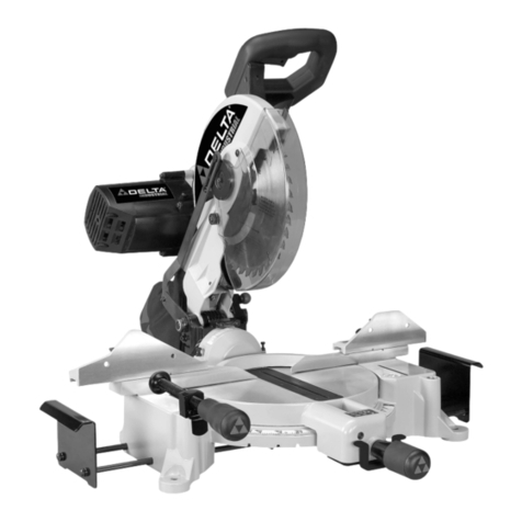
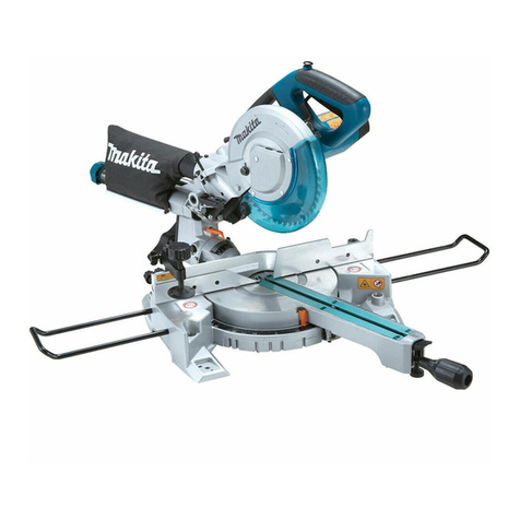
TONI TMS210F Setup guide

1

Product specifications
….……………………………………………………………...
3
Know your machine ……………………………………………………………..………....
4
Symbols ………………………………………………………………….... …………………
5
General safety warnings………………………………………………………….……….....
6
Safety safety information for mitre saw ………………..………....………………..…
8
Assembly and installation …………………………………….………....
10
Operation ………………………………………………….……….....
14
Maintenance …………………………………..………....………………………..………...
16
Exploded view……………………………………………………………….....
17
Parts list ………………………………………………………………………….……….....
18
Warranty …………………………………………………………………….……………...….
19
TABLE OF CONTENTS
2

PRODUCT SPECIFICATIONS
PRODUCT SPECIFICATIONS
Voltage / Frequency:
230V AC, 50Hz
Rated power:
1200W
Speed:
5,000 RPM (no load)
Blade:
255mm 24 tooth general purpose
carbide-tipped
Spindle size:
30mm
Laser:
Class IIl
Laser wavelength:
650nm
Laser output power:
<2.5mW
Mitre range:
0–45° left or right
Bevel range:
0–45° left
Cutting capacity:
90° cross cut 60 x 120 mm
45° mitre cut 60 x 80 mm
45° bevel cut 35 x 120 mm
45° mitre/bevel cut 35 x 80 mm
Weight:
8kgs
3

1
2
3
5
4
1
8
2
5
3
12
10
9
11
6
7
17
16
13
14
15
4
No.
Parts name
No.
Parts name
1
Switch trigger
11
Fence
2
Lock-off switch
12
Movable guard (Lower guard)
3
Laser
13
Lift handle
4
LED light
14
Laser switch
5
Dust bag
15
LED light switch
6
Workpiece clamp
16
Bevel lock knob
7
Extension bar
17
Rear support bar
8
Mitre scale
9
Base
10
Rotation work table
Accessories
1. Rear support bar
2. Extension bar
3. Workpiece clamp
4. Hexagon key
5. Dust bag
KNOW YOUR MACHINE
4

Read all safety warnings and instructions
Protective grounding at grounding terminal, Class I tools
Warning symbol
Wear your safety glasses
Wear breathing protection;
Wear hearing protection
Keep hands away from blade
WARNING: To avoid electrical hazards, fire hazards or
damage to the tool, use proper circuit protection.
Laser light.
Do not look directly into the laser beam
Wear hand protection.
Always disconnect from the power supply when
adjusting, changing accessories, cleaning, carrying out
maintenance and when not in use!
Warning: Sharp blades or teeth!
DO NOT use in rain or damp environments!
Environmental Protection
Waste electrical products should not be disposed of with
household waste.
Please recycle where facilities exist. Check with your
local authority or retailer for recycling advice.
Conforms to relevant legislation and safety standards.
WARNING:
Some of the following symbols may appear on the Machine. Study
these symbols and learn their meaning. Proper interpretation of these symbols will
allow for more efficient and safer operation of this tool.
!
SYMBOLS
5

!
WARNING: Read all safety warnings and all instructions. Failure to follow the
warnings and instructions may result in electric shock, fire and/or serious injury.
!
WARNING: This appliance is not intended for use by persons (including children) with
reduced, physical or mental capabilities or lack of experience or knowledge unless they
have been given supervision or instruction concerning use of the machine by a person
responsible for their safety. Children must be supervised to ensure that they do not play
with the machine.
Save all warnings and instructions for future reference.
Work area safety
Keep work area clean and well lit. Cluttered or dark areas invite accidents.
Do not operate power tools in explosive atmospheres, such as in the presence of
flammable liquids, gases or dust. Power tools create sparks which may ignite the dust or
fumes.
Keep children and bystanders away while operating a power tool. Distractions can cause
you to lose control.
Make the workshop childproof. Use padlocks, master switches. Always remove starter keys.
Never leave a power tool running while it is unattended. Turn the power switch OFF and do
not leave the area until the tool has come to a complete stop.
Electrical safety
Power tool plugs must match the outlet. Never modify the plug in any way. Do not use
any adapter plugs with earthed (grounded) power tools. Unmodified plugs and matching
outlets will reduce risk of electric shock.
Avoid body contact with earthed or grounded surfaces such as pipes, radiators, ranges
and refrigerators. There is an increased risk of electric shock if your body is earthed or
grounded.
Do not expose power tools to rain or wet conditions. Water entering a power tool will
increase the risk of electric shock.
Do not abuse the cord. Never use the cord for pulling or unplugging the power tool. Keep
cord away from heat, oil, sharp edges or moving parts. Damaged or entangled cords
increase the risk of electric shock.
When operating a power tool outdoors, use an extension cord suitable for outdoor use.
Use of a cord suitable for outdoor use reduces the risk of electric shock.
If operating a power tool in a damp location is unavoidable, use a residual current device
(RCD) protected supply. Use of a ground fault circuit interrupter (GFCI) reduces the risk
of electric shock.
Personal safety
Stay alert, watch what you are doing and use common sense when operating a power
tool. Do not use a power tool while you are tired or under the influence of drugs, alcohol
or medication. A moment of inattention while operating power tools may result in serious
personal injury.
Use personal protective equipment. Always wear eye protection. Protective equipment
such as dust mask, non-skid safety shoes, hard hat, or hearing protection used for
appropriate conditions will reduce personal injuries.
Prevent unintentional starting. Ensure the switch is in the off-position before connecting
to power source, picking up or carrying the tool. Carrying power tools with your finger on
the switch or energizing power tools that have the switch ON invites accidents.
GENERAL SAFETY WARNINGS
6

Remove any adjusting key or wrench before turning the power tool on. A wrench or a key
left attached to a rotating part of the power tool may result in personal injury.
Do not overreach. Keep proper footing and balance at all times. This enables better control
of the power tool in unexpected situations.
Dress properly. Do not wear loose clothing or jewelry. Keep your hair, clothing and
gloves away from moving parts. Loose clothes, jewelry or long hair can be caught in moving
parts.
If devices are provided for the connection of dust extraction and collection facilities,
ensure these are connected and properly used. Use of dust collection can reduce dust-
related hazards.
Bench-top power tool use and care
Do not force the power tool. Use the correct power tool for your application. The correct
power tool will do the job better and safer at the rate for which it was designed.
Do not use the power tool if the switch does not turn it on and off. Any power tool that
cannot be controlled with the switch is dangerous and must be repaired.
Disconnect the plug from the power source before making any adjustments, changing
accessories, cleaning, or storing power tools. Such preventive safety measures reduce the
risk of starting the power tool accidentally.
Store idle power tools out of the reach of children and do not allow persons unfamiliar
with the power tool or these instructions to operate the power tool. Power tools are
dangerous in the hands of untrained users.
Maintain power tools. Check for misalignment or binding of moving parts, breakage of
parts and any other condition that may affect the power tool’s operation. If damaged,
have the power tool repaired before use. Many accidents are caused by poorly maintained
power tools.
Each time the tool is used, make sure the guards are in place and working properly.
Keep cutting tools sharp and clean. Properly maintained cutting tools with sharp cutting
edges are less likely to bind and are easier to control.
Use only accessories that are recommended for the tool. Consult your Owner’s Manual for
recommended accessories. The use of improper accessories may cause risk of injury.
Use the power tool, accessories and tool bits etc. in accordance with these instructions,
taking into account the working conditions and the work to be performed. Use of the
power tool for operations different from those intended could result in a hazardous situation.
Use clamps or another practical way to secure and support the workpiece. Holding the
workpiece by hand or against your body leaves it unstable and may lead to loss of control.
Never stand on a power tool. Serious injury could result if the tool tips or is accidentally hit. Do
NOT store anything above or near a power tool.
Service
Have your power tool serviced by a qualified repair person using only identical
replacement parts. This will ensure that the safety of the power tool is maintained.
Sound and vibration Sound and vibration values were measured in accordance with EN 61029.
LpA sound pressure level .....................93,5 dB(A)
KpA uncertainty .............................................3 dB
LWA sound power level .....................106,5 dB(A)
KWA uncertainty .............................................3 dB
GENERAL SAFETY WARNINGS
7

!
WARNING: Know your MITRE saw. Do not plug in the mitre saw until you have read and
understand this Owner’s Manual. Learn the tool’s applications and limitations, as well as the
potential hazards related to this tool. Following this rule will reduce the risk of electric shock, fire, or
serious injury.
!
Always wear eye protection. Any power tool can throw foreign objects into your eyes
and cause permanent eye damage. ALWAYS wear safety goggles (not glasses) that
comply with safety standard.
!
WARNING: In addition to wearing eye protection, always wear hearing protection and a
dust mask. Use only in well-ventilated areas. Using personal safety devices and working in a safe
environment reduces the risk of injury.
This tool is equipped with an electrical cord that has an equipment-grounding conductor
and a grounding plug. The plug must be plugged into a matching receptacle that is properly
installed and grounded in accordance with all local codes and ordinances.
FIRMLY CLAMP OR BOLT your tool to a workbench or table at approximately hip height.
KEEP HANDS AWAY FROM CUTTING AREA. Do not reach underneath work or in blade
cutting path with your hands and fingers for any reason. Always turn the power off.
ALWAYS SUPPORT LONG WORKPIECES while cutting to minimize risk of blade pinching and
kickback. Saw may slip, walk or slide while cutting long or heavy boards.
ALWAYS USE A CLAMP to secure the workpiece when possible.
BE SURE THE BLADE CLEARS THE WORKPIECE. Never start the saw with the blade
touching the workpiece. Allow motor to come up to full speed before starting cut.
MAKE SURE THE MITER TABLE AND SAW ARM (BEVEL FUNCTION) ARE LOCKED IN
POSITION BEFORE OPERATING YOUR SAW. Lock the miter table by securely tightening the
miter lock levers. Lock the saw arm (bevel function) by securely tightening the bevel lock knob.
NEVER USE A LENGTH STOP ON THE FREE SCRAP END OF A CLAMPED WORKPIECE.
NEVER hold onto or bind the free scrap end of the workpiece in any opera-tion. If a work clamp
and length stop are used together, they must both be installed on the same side of the saw table
to prevent the saw from catching the loose end and kicking up.
NEVER cut more than one piece at a time. DO NOT STACK more than one workpiece on the
saw table at a time.
NEVER PERFORM ANY OPERATION FREEHAND. Always place the workpiece to be cut on
the miter table and position it firmly against the fence as a backstop. Always use the fence.
NEVER hand hold a workpiece that is too small to be clamped. Keep hands clear of the cutting
area.
NEVER reach behind, under, or within three inches of the blade and its cutting path with your
hands and fingers for any reason
NEVER reach to pick up a workpiece, a piece of scrap, or anything else that is in or near the
cutting path of the blade.
AVOID AWKWARD OPERATIONS AND HAND POSITIONS where a sudden slip could cause
your hand to move into the blade.
ALWAYS make sure you have good balance.
NEVER operate your miter saw on the floor or in a crouched position.
SAFETY INFORMATION FOR MITRE SAW
8

!
NEVER stand or have any part of your body in line with the path of the saw blade.ALWAYS
release the power switch and allow the saw blade to stop rotating before raising it out of the
workpiece.
DO NOT TURN THE MOTOR SWITCH ON AND OFF RAPIDLY. This could cause the saw
blade to loosen and could create a hazard. Should this ever occur, stand clear and allow the
saw blade to come to a complete stop. Disconnect your saw from the power supply and securely
retighten the blade bolt.
IF ANY PART OF THIS MITER SAW IS MISSING or should break, bend, or fail in any way, or
should any electrical component fail to perform properly, shut off the power switch, remove the
miter saw plug from the power source and have damaged, missing, or failed parts replaced
before resuming operation.
IF THE POWER SUPPLY CORD IS DAMAGED, it must be replaced only by the manufacturer
or by an authorized service center to avoid risk.
ALWAYS STAY ALERT! Do not allow familiarity (gained from frequent use of your saw) to
cause a careless mis-take. ALWAYS REMEMBER that a careless fraction of a second is
sufficient to inflict severe injury.
MAKE SURE THE WORK AREA HAS AMPLE LIGHTING to see the work and that no
obstructions will interfere with safe operation BEFORE performing any work using your saw.
ALWAYS TURN OFF THE SAW before disconnecting it to avoid accidental starting when
reconnecting to power supply. NEVER leave the saw unattended while connected to a power
source.
THIS TOOL should have the following markings:
WARNING: Use caution when handling blades. They are very sharp.
WARNING: Never touch the blade immediately after turning the scroll saw OFF. The blade will
be extremely hot.
a) Wear eye protection.
b) Keep hands out of path of saw blade.
c) Do not operate saw without guards in place.
d) Do not perform any operation freehand.
e) Never reach around saw blade.
f) Turn off tool and wait for saw blade to stop before moving work piece or changing settings.
g) Disconnect power (or unplug tool as applicable) before changing blade or servicing.
h) No load speed.
ALWAYS carry the tool only by the carrying handle.
AVOID direct eye exposure when using the laser guide.
SAVE THESE INSTRUCTIONS. Refer to them frequently and use to instruct other users. If
you loan someone this tool, loan them these instructions also.
WARNING: Some dust created by power sanding, sawing, grinding, drilling, and other
construction activities contains chemicals known to cause cancer, birth defects or other reproductive
harm. Some examples of these chemicals are: • lead from lead-based paints, • crystalline silica from
bricks and cement and other masonry products, and • arsenic and chromium from chemically-treated
lumber. Your risk from these exposures varies, depending on how often you do this type of work. To
reduce your exposure to these chemicals: work in a well ventilated area, and work with approved
!
!
SAFETY INFORMATION FOR MITRE SAW
9

!
Fi 2
safety equipment, such as those dust masks that are specially designed to filter out microscopic
particles.
WARNING: Never look directly into the laser beam. Direct exposure to your eyes could
cause blindness.
CUTTING HEAD LOCK-DOWN (See Figure 1)
This mitre saw is shipped with the cutting head locked in the DOWN position. The lock-down system
must be used when moving, transporting or lifting the mitre saw to prevent the cutting head from
shifting. It also makes lifting the mitre saw easier and safer.
WARNING: Never turn the mitre saw ON when the cutting head is locked in the DOWN position.
Always unlock the lock-down pin and allow the cutting head to rise to its maximum height before
turning the mitre saw ON.
To unlock the lock-down pin:
1. Use your left hand to slightly push downward on the main handle.
2. While holding the main handle down, use your right hand to pull the lock-down knob (1) outward.
3. Lift your left hand and allow the cutting head to rise to its maximum height.
To lock the cutting head in the DOWN position, push the lock-down knob(1) inward until the knob is
insert the hole (2).
DUST BAG (See Figure 2.)
A dust bag is provided for use on this miter saw. It fits over the dust guide on the upper blade guard.
To install it, squeeze the two metal clips to open the mouth of the bag and slide it on the dust guide.
Release the clips. The metal ring in the bag should lock in between the grooves on the dust guide.
To remove the dust bag for emptying, simply reverse the above procedure.
ASSEMBLY AND INSTALLATION
!
Fig. 1
1
2
2
1
10

TABLE EXTENSION See Figure 3.
The base extension supports are designed to provide a wider surface upon which the workpiece will
rest. There are two base extension supports. Using the base extension supports will help in producing
more accurate cuts.
- Loosing the lock screw with a screwdriver (1).
- Insert the two base extension support rods (2) into the matching holes in the base casting.
- Tighten the lock screw (1).
INSTALLING THE REAR BALANCE SUPPORT
1. Lock the cutting head in the down position and carefully roll the mitre saw approx. 150° counter
clockwise on a clean sheet of corrugated to expose the under side of the base (Fig. 5).
2. Use a #2 screwdriver and turn the balance support locking screw (1) counter clockwise until the
leg of the balance support (2) can be inserted into the hole in the base casting (3).
3. Insert both legs (2 & 4) of the balance support into the matching holes (3 & 5) in the base casting.
NOTE: Make sure the turned-down portion of the balance support (6) is facing the bottom of the
base casting.
4. Slide the balance support rods into the mounting holes until they protrude at least 12mm past the
casting.
5. Tighten the balance support locking screw to lock the balance support into the base casting.
6. Carefully turn the mitre saw upright.
ASSEMBLY AND INSTALLATION
Fig. 3
Fig. 5
11

1
2
3
4
Fig. 5
Fig.6
1
5
3
4
2
WORK CLAMP(Fig. 5).
WARNING: In some operations, the work clamp assembly may interfere with the operation of
the blade guard assembly.
Always make sure there is no interference with the blade guard prior to beginning any cutting
operation to reduce the risk of serious personal injury.
The work clamp is used to hold the long section of the workpiece firmly in place while making a cut.
NOTES:
There is a clamp rod hole in the left rear corner of the base that
may be more convenient for holding some workpieces that are
odd shapes.
1. Insert the work clamp rod (1) into the clamp rod hole (2)
located in the left rear corner of the base
2. Loosen the cross bar adjusting knob (4) and slide the
cross bar up or down until it is approximately 60 mm
above the base.
3. Tighten the clamp rod lock knob(3).
INSTALLING A NEW BLADE
A blade should be replaced if it is dull, bent or broken.
1. Turn the mitre saw switch OFF and remove the plug from the power source.
NOTE: Do NOT touch the blade immediately after use. It will be extremely hot. Wait at least five
minutes for the blade to cool.
2. Raise saw arm.
3. Rotate lower blade guard(1) up as far as it will go.
4. Depress the spindle lock button(2) and rotate the hex bolt(3) until the spindle locks.
5. Using the hexagon key(4) provided, loosen and remove the hex bolt(3).
NOTE: The hex bolt has left hand threads. Turn hex bolt clockwise to loosen.
6. Remove the outer blade flange(5). Do not remove the inner blade flange.
7. Fit saw blade inside lower blade guard and onto spindle. The blade teeth point downward at the
front of saw as shown in figure 6.
!
ASSEMBLY AND INSTALLATION
12

Fig.7
2
1
Fig.8
Work table
Mitre indicator
Mitre scale
WARNING: If inner blade flange has been removed, replace it before placing blade on spindle.
Failure to do so could cause an accident since blade will not tighten properly.
WARNING: Always install the blade with the blade teeth and the arrow printed on the side of the
blade pointing down at the front of the saw. The direction of blade rotation is also stamped with an
arrow on the upper blade guard.
8. Replace outer blade flange. The double "D" flats on the blade flanges align with the flats on the
spindle.
9. Depress spindle lock button and replace hex bolt. NOTE: The hex bolt has left hand threads.
Turn blade bolt counterclockwise to tighten.
10. Tighten hex bolt securely.
WARNING: Make sure the spindle lock button is not engaged before reconnecting saw into
power source. Never engage spindle lock button when blade is rotating.
ADJUSTING THE BEVEL ANGLE
1. Loose the bevel angle locking knob (1) by turning it counter clockwise to allow the cutting head (2)
to rotate (Fig. 7). When rotate to intended angle, tighten the locking knob(1).
ADJUSTING THE MITRE ANGLE (see figure 8)
The mitre saw can be cutting as mitre angle -45°to 0°to +45°, and the mitre angle have not a locking
device, you can move the cutting head left or right to rotate the work table to set the cutting mitre
angle.
ASSEMBLY AND INSTALLATION
!
!
!
13

!
Fig.9
2
CAUTION:
Make sure the blade is not contacting the workpiece, etc, before the switch is turned on .
LASER & WORKLIGHT ON/OFF SWITCH (Fig.9)
The laser and worklight are turned ON and OFF with two switches. Left side is laser switch (1), right
side is worklight switch(2).
To turn the switch ON, press the front edge of the switch.
To turn the switch OFF, press the rear edge of the switch.
WARNING: Never stare directly at the laser beam. It
can severely damage your eyes.
LOCK-OFF SWITCHES (Fig.9)
This tool is equipped with two lock-off switches (3) to
prevent unintentional starting. Two lock-off switches are
supplied to accommodate both right and left hand operation
of the tool. ONE of these lock-off switches must be pressed
and held before the tool will start.
TRIGGER SWITCH (Fig.9)
To turn the tool ON, press and hold one of the lock-off
switches, then squeeze the trigger switch (4). Once the tool
starts, you can release the lock-off switch while continuing to
squeeze the trigger switch. To turn the tool OFF, release the
trigger switch.
NOTE: Once the trigger switch has been released, the tool
cannot be restarted without pressing and holding a lock-off switch before squeezing the trigger switch.
BEVEL CUTTING
1. Loose the bevel angle locking knob (1) by turning it counter clockwise to allow the cutting head (2)
to rotate (Fig. 7). When rotate to intended angle, tighten the locking knob(1).
WARNING: Make sure that the lower blade guard C is installed before using.
CAUTION:
1. Do not apply excessive pressure on the handle when cutting. Too much force may result in
overload of the motor and/of decreased cutting efficiency. Push down handle with only as much
force as is necessary for smooth cutting and without significant decrease in blade speed.
2. Always be sure that the blade will move down to bevel direction during a bevel cut. Keep hands
out of path of saw blade.
3. During a bevel cut, it may create a condition whereby the piece cut off will come to rest against
the side of the blade. If the blade is raised while the blade is still rotating, this piece may be
caught by the blade, causing fragments to be scattered which is dangerous. The blade should be
raised ONLY after the blade has come to a complete stop.When pressing the handle down, apply
pressure parallel to the blade. If the pressure is not parallel to the blade during a cut, the angle of
the blade might be shifted and the precision of the cut will be impaired.
OPERATION
!
14

Press cutting
Secure the workpiece against guide fence and turn table. Switch on the tool without the blade making
any contact and wait until the blade attains full speed before lowering. Then gently lower the handle to
the fully lowered position to cut the workpiece. When the cut is completed. Switch off the tool and wait
until the blade has come to a complete stop before returning the blade to its fully elevated position.
Mitre cutting
Refer to the previously covered “Adjusting the Mitre angle”.
CUTTING BASE MOLDING
Base moldings and trims can be cut on a compound mitre saw. The method depends upon the type of
molding, its characteristics and its applications (Fig. 10).
1. Use the wokpiece clamp whenever possible. Place tape on the area being clamped to avoid
marking the finish surface of the molding.
2. Tape the area being cut to avoid splintering, and mark the cut line on the tape.
3. Perform practice cuts on scrap pieces before cutting the final molding.
NOTE: Splintering may be caused due to the thinness of the molding or use of the wrong type of
saw blade.
OPERATION
Fig. 10
15

MAINTENANCE
WARNING:
Ensure that the tool is switched off and the plug is removed from the
power point before making any adjustments or carrying out maintenance procedures.
WARNING
:
ALWAYS wear protective equipment including eye protection and gloves
when cleaning this tool.
Cleaning
• Keep all safety devices, air vents and the motor housing free of dirt and dust as far as possible.
Wipe the equipment with a clean cloth or blow it with compressed air at low pressure.
• We recommend that you clean the device immediately each time you have finished using it.
• Clean the equipment regularly with a moist cloth and some soft soap. Do not use cleaning agents or
solvents; these could attack the plastic parts of the equipment.
- Ensure that no water can seep into the device.
Danger! Always pull out the mains power plug before starting any cleaning work.
- Bearings
Lubricate the bearings of the guide rollers periodically with high-grade machine grease, but at least
after every 25-30 hours in operation.
- Carbon brushes In case of excessive sparking have the carbon brushes checked only by a qualified
electrician.
Important! The carbon brushes should not be replaced by anyone but a qualified electrician.
- Maintenance
There are no parts inside the equipment which require additional maintenance.
- Ordering replacement parts:
Please quote the following data when ordering replacement parts:
• Type of machine
• Article number of the machine
• Identification number of the machine
• Replacement part number of the part required.
DISPOSAL AND RECYCLING
The unit is supplied in packaging to prevent its being damaged in transit. This packaging is raw
material and can therefore be reused or can be returned to the raw material system.
The unit and its accessories are made of various types of material, such as metal and plastic.
Defective components must be disposed of as special waste. Ask your dealer or your local council.
STORAGESTORE
The equipment and accessories out of children’s reach in a dark and dry place at above freezing
temperature. The ideal storage temperature is between 5 and 30 °C. Store the electric tool in its
original packaging.
MAINTENANCE
16

EXPLODED VIEW
17

NO DESCRIPTION NO DESCRIPTION NO DESCRIPTION
1 extension bar 54 lock switch button (left) 106608 bearing
2 M6×14 screw 55 coonnection sheet107 ST4.8×60 tapping screw
3base 56 lock switch button (right) 108 stator
4base pad 57 pin 109housing
5
M4×12 tapping screw
58 transformer 110 brush holder cap
6 scaler 59 M5×20 bolt 111 carbon brush
7φ8×φ24×2 flat washer 60 handle 112 brush holder
8 M8 lock nut 61 cord pressure plate 113 label
9 M8×8 bolt 62 cord guard 114 M5×40 screw
10 spring 63 plug 115φ5×φ10×0.5 flat washer
11 φ8 steelball 64 Switch 1166200 bearing
12 hexagon key 65 switch trigger 117 spring
13 M6 screw 66 capacitor 118φ8 circlip
14 movable fence 67 inductor 119 spring seat
15 M5×10 screw 68 Switch 120 M3×8 screw
16 anti-drop support 69 lift handle 121hexagon key
17 M4×8 screw 70 ST6×18 tapping screw 122 torque shaft
18 down guard 71 handle cover 123deflector rod
19 Fix plate for angle adjustment 72 ST3.9×12 tapping screw 124 M4×12 pan head screw
20 M6 nut 73 M5×25 screw 125 small torque spring
21 rotation work table 74 M8×18 bolt 126 M4×6 bolt
22 Friction sheet(big) 75 outer flange 127 M4×14 screw
23 M6×35 knob 76 blade128 laser guard cover
25 M6×25 screw 77 inner flange 129M4 nut
26 φ6 spring washer 78 M5×16 tapping screw 130 laser
27 M6×12 knob 79 φ5 spring washer131φ3 flat washer
28 fence 80 bearing fix plate 132 laser base
29 M8×30 center shaft 81 spindle 133φ4 wave washer
30 the slot guard in the table 82 woodruff key 134dust defender
31 M8×50 bolt 83 6002 bearing 135 label
32 bracket base 84 Bearing house 136φ6×φ16×1.2 flat washer
33 M6×20 bolt 85 φ15 circlip for shaft 137 connection rod
34 M6×18 bolt 86 big gear138 HK0709 needle bearing
35 M6×16 bolt 87 φ12 circlip for shaft 139 M6 bolt
36 short shaft 88 Needle bearing HK0910140 screw
37 M5×6 bolt 89 rubberpad141φ8×φ16×1.2 flat washer
38 M5×22 bolt 90 defender of blade guard 142φ6×φ12×0.5 flat washer
39 M5 nut 91 upper blade guard 143 M6×20 screw
40 bracket 92 M5×8 bolt 144 small blade guard cover
41 ball knob 93 LED cord clamp 145 small blade guard
42 φ8.5×1.9"O" Ring 94 LEDbox cover 146 spring
43 Lock Pin 95 reflector 147 movable blade guard
44 M5 bolt 96 LEDlight 148
M5×12
bolt
45 bush 97 LEDbox149 big blade guard cover
46 M5 nut 98 Transparent plate 150φ6×φ12×2 flat washer
47 Lock knob for angel adjustment 99 Collection dust bag151 M6 nut
48 φ8×φ22×2 flat washer100 rubberbush 152 Cable Clip
49 M4×6 bolt 101 screw 153 M4×8 bolt
50 indicator 102 spindle lock 154 ST2.9×6 tapping screw
51 Pin 103 spindle lock button 155 washer
52 big torque spring 104 wind defender156 M4×8 tapping screw
53 spring for switch 105 rotor 157 M5×8 bolt
Clamp assembly
01 M4 screw 04 small connection bar 07 locating rod
02 pressure plate 05 wheel knob
03 φ4×φ10×0.5 flat washer 06 M6×12 thumb knob
PARTS LIST
18

LIMITED WARRANTY
Toni warrants this product for a period of 1 year. It is a limited warranty. You must
complete the warranty certificate in full, immediately when you purchase this machine.
You must fax, or scan and email as per instruction on the warranty certificate.
WHAT THIS WARRANTY COVERS: This warranty covers all defects in workmanship
and materials for a period of 1 year from the date of purchase, provided that:
a/. The table saw has been used in accordance with the manufacturer’s intended use.
b/. During the warranty period service and repairs must be carried out by authorized
service centre using original parts.
c/. The unit is serviced regularly (after every 10 hours of usage).
We will repair any faulty workmanship, and either repair or replace any defective part,
at our discretion. We will do so without any charge. We will complete the work in a
reasonable time, but, in any case, within ninety days or less. PROOF OF PURCHASE
NEEDS TO BE PRODUCED and the Warranty Certificate, with any warranty claim.
WHAT’S NOT COVERED UNDER WARRANTY: This warranty applies only to the
original purchaser at retail and may not be transferred. This warranty only covers
defects arising under normal usage and does not cover any malfunction, failure or
defects resulting from misuse, abuse, neglect, alteration, modification or repairs by other
than Toni approved service agents. It does not cover the accessories. It does not cover
the fair wear and tear of the parts. Brushes, bearings and accessories are normal wear
and tear parts. This warranty does not cover commercial use of the tool.
ADDITIONAL LIMITATIONS: This warranty is limited to a period of 1 years from the
date of purchase. Toni is not responsible for direct, indirect, or incidental damages, for
the failure of the product. Toni will not be responsible for any damages or personal
injury caused by the use, misuse or failure of the product, under any circumstances.
HOW TO GET SERVICE: Return the power tool, properly packaged and postage
prepaid, to an Authorized Service Center or your dealer. You can obtain the location of
the Service Center nearest to you by contacting a service representative at
you must present the warranty certificate with the proof of purchase documentation, and
all the necessary packaging and accessories.
KEEP THIS INSTRUCTION MANUAL & WARRANTY
CONDITIONS FOR FUTURE REFERENCE.
WARRANTY
19
Table of contents
