Toolex 598557 User manual

INSTRUCTION MANUAL
598557
BELT & DISC LINISHING SANDER
550WATT MOTOR & VARIABLE SPEED
25MM X 762MM BELT SIZE
150MM DISC SIZE
CONSUMER SERVICE CENTRE
PO BOX 1012
HAMILTON NSW 2303 AUSTRALIA
Made in P.R.C.

Page 2
2
TABLE OF CONTENTS
SPECIFICATIONS
Safety Instructions..............................................................................................................................3 - 5
Contents of Package .......................................................................................................................................6
Getting to Know Your Sander ..........................................................................................................................7
Assembly ........................................................................................................................... 7 - 9
Adjustments .......................................................................................................................... 9 - 11
General Use........................................................................................................................................12
Troubleshooting........................................................................................................................................13 - 14
Maintenance ...................................................................................................................................14
Parts Diagram ................................................................................................................................15
This owner’s manual is not a teaching aid and is intended to show
assembly, adjustments, and general use.
Motor ..................................................550W S2 30min, 230V, 50Hz
Motor Speed (variable) ...................................... 2,000 - 2,850 RPM
Belt Size ....................................................................... 25 x 762mm
Belt Speed (variable) ....................................... 1,900 - 2,700 SFPM
Belt Table Size ..................................................... 146mm Diameter
Belt Table Tilt ........................................................................... 0-45°
Disc Size .............................................................................. 150mm
Disc Speed (variable) ........................................ 2,000 - 2,850 RPM
Disc Table .................................................................... 204x135mm
Disc Table Tilt .......................................................................... 0-45°
Miter Gauge ....................................................................... Included
Miter Gauge Slot ........................................................... 16x6.5 mm
Base Size .................................................................... 170x235mm
Dust Ports (2) ............. 45mm OD/ 38mm ID & 38mm OD/ 32mm ID
Net Weight ......................................................................... 13.7 kgs
Shipping Weight .................................................................... 15 kgs

Page 3
SAFETY SYMBOLS
3
SAFETY SYMBOLS
IMPORTANT! Safety is the single most important consideration in the operation of this equipment. The following
instructions must be followed at all times. Failure to follow all instructions listed below may result in electric shock,
There are certain applications for which this tool was designed. W
and/or used for any other application other than that for which it was designed. If you have any questions about its
application, do not use the tool until you have contacted us and we have advised you.
GENERAL SAFETY
KNOW YOUR POWER TOOL. Read the owner’s manual
carefully. Learn the tool’s applications, work capabilities,
BEFORE USING YOUR MACHINE
To avoid serious injury and damage to the tool, read and
follow all of the Safety and Operating Instructions before
operating the machine.
1. ALWAYS
2. ALWAYS use a face or dust mask if the operation is
particularly dusty.
3. ALWAYS
check for damage before using the machine,
check for alignment of moving parts, breakage of parts,
and any other condition that may affect the machines
operation. Damage should be properly repaired or the
part replaced. If in doubt, DO NOT use the machine.
Consult your local dealer.
4. ALWAYS disconnect the machine from the power
supply before servicing and when changing
accessories.
6. ALWAYS keep work area clean. Cluttered areas and
benches invite accidents.
7. ALWAYS ensure that adequate lighting is available.
Ensure that lighting is placed so that you will not be
working in your own shadow.
8. ALWAYS keep children away. All visitors should be
kept a safe distance from the work area, especially
when the machine is being used.
9. ALWAYS maintain machine in top condition. Keep
tools/machines clean for the best and safest
performance. Follow maintenance instructions.
10.ALWAYS handle with extreme care and do not carry
the tool/machine by its electric cable, or pull on the
cable to disconnect it from the power supply.
11.ALWAYS ensure the switch is off before plugging in to
mains. Avoid accidental starting.
12.ALWAYS concentrate on the job in hand, no matter
how trivial it may seem. Be aware that accidents are
caused by carelessness due to familiarity.
13.ALWAYS keep your proper footing and balance at all
times - don’t overreach. For best footing, wear rubber
soled footwear. Keep floor clear of oil, scrap wood, etc.
5. ALWAYS wear safety goggles, manufactured to the
latest Australian Safety Standards. Everyday
eyeglasses do not have impact resistant lenses, and
are not safety glasses.
learn the machines applications, limitations
and the specific potential hazards. Read and become
familiar with the entire operating manual.
SAFETY ALERT SYMBOL: Indicates DANGER, WARNING, or CAUTION. This symbol may be used
in conjunction with other symbols or pictographs.
Indicates an imminently hazardous situation, which, if not avoided, could result in death or
serious injury.
Indicates a potentially hazardous situation, which, if not avoided, could result in death or serious
injury.
Indicates a potentially hazardous situation, which, if not avoided, could result in minor or
moderate injury.
NOTICE: Shown without Safety Alert Symbol indicates a situation that may result in property damage.

Page 4
4
SAFETY INSTRUCTIONS
14.ALWAYS dress properly. Loose clothing or jewellery
may get caught in moving parts. Wear protective hair
covering to contain long hair.
15.ALWAYS guard against electric shock. Avoid contact
with earthed surfaces - pipes, radiators etc.
16.NEVER operate machine while under the influence of
drugs, alcohol or any medication.
17.NEVER leave machine running unattended. Turn
power off. Do not leave the machine until it comes to
a complete stop.
18.NEVER force the machine, it will do a better and safer
job at the rate for which it was designed.
19.NEVER use power tools in damp or wet locations or
expose them to rain. Do not use in an explosive
atmosphere (around paint, flammable liquids etc.).
Avoid dangerous environments.
19.If the tool begins to make an abnormal noise, or
produce excessive vibrations, smoke or burning odour,
turn the tool off immediately and do not operate, until
repaired.

Page 5
5
SAFETY INSTRUCTIONS
1. ALWAYS wear ear protectors/defenders when using this machine.
2. ALWAYS wear a dust mask when using this machine. Be aware that harmful or toxic dusts could be
produced when sanding some woods.
3. ALWAYS use the table to support the workpiece.
4. ALWAYS check to ensure the table and attachments are secure before starting.
5. ALWAYS maintain a clearance of 2-3mm between table and sanding disc.
6. ALWAYS hold the workpiece firmly so that it cannot be torn from your hands.
7. ALWAYS feed the workpiece against the direction of rotation of the disc. i.e the LEFT side of the disc.
8. ALWAYS keep the mains cable well away from the machine and ensure an adequate electrical supply
is close at hand so that the operation is not restricted by the length of the cable.
9. ALWAYS use a dust extraction device, properly connected to the dust extraction port.
10. ALWAYS ensure that nails or foreign objects have been removed from a workpiece beforehand. Nails
etc. will destroy the belt or disc.
11. NEVER allow the ventilation slots in the motor to become blocked.
12. NEVER sand pieces which cannot be held firmly by hand.
SPECIFIC SAFETY INSTRUCTIONS FOR SANDERS
This machine is intended for the surfacing of natural, solid woods and composite materials. Any other use not
manufacturer can cause unforeseen damage, and invalidate the warranty.
ATTENTION: Use of this sander still presents risks that cannot be eliminated by the manufacturer. Therefore,
the user must be aware that wood working machines are dangerous if not used with care and all safety
precautions are adhered to.
SAVE THESE INSTRUCTIONS. Refer to them often.
This owner’s manual is not a teaching aid and is intended to show
assembly, adjustments, and general use.

Page 6
CONTENTS OF PACKAGE
6
UNPACKING AND CLEAN-UP
1. Carefully remove all contents from the shipping carton. Compare the contents with the list of contents to
make sure that all of the items are accounted for, before discarding any packing material. Place parts on a
DO NOT turn your machine ON if any
are missing. You may cause injury to yourself or damage to the machine.
of these items
2. Report any shipping damage to your local distributor. Take photographs for any possible insurance claims.
3. Clean all rust protected surfaces with ordinary house hold type grease or spot remover. Do not use;
gasoline, paint thinner, mineral spirits, etc. These may damage painted surfaces.
4. Apply a coat of paste wax to the table to prevent rust. Wipe all parts thoroughly with a clean dry cloth.
5. Set packing material and shipping carton aside. Do not discard until the machine has been set up and is
running properly.
TABLE OF LOOSE PARTS
A. Belt & Disc Sander Assembly
B. Sanding Belt Table
C. Lever Handle for Sanding Belt Table
D. Washer 8mm
E. Miter Gauge
F. Hex W rench 3mm
G. Sanding Disc Table
H. Spring Washers 6mm (2)
I. W ashers 6mm (2)
J. Locking Handles for Sanding Disc Table (2)
K. Manual & Warranty Card (not shown)
A
B
C
D
E
F
G
H
I
J
Note: Not Actual Toolex Product Pictured below

Page 7
GETTING TO KNOW YOUR SANDER
A
B
C
D
EFG
H
I
J
K
7
ASSEMBLY
Tools Required for Assembly:
A. Sanding Belt 25mm x 762mm
B. Sanding Belt Tracking Knob
C. Sanding Belt Table
D. Sanding Belt Table Lock Handle
E. ON/OFF Safety Switch
F. Speed Control Switch
G. Mounting Hole in Base
H. Disc Table Angle Scale & Lock Knob
I. Sanding Disc Table
J. Miter Gauge
K. Sanding Disc 150mm
L. Sanding Belt Safety Cover
M. Platen for Sanding Belt
N. Motor
O. Sanding Disc Aluminum Disc
P. Sanding Disc Guard & Dust Port
Q. Rubber Machine Feet (4)
R. Power Cord
S. Sanding Belt Dust Port (not shown)
T. Sanding Belt Guard
INSTALLATION
MOVING & INSTALLING THE SANDER
When moving the sander, lift the
machine with your hands positioned under the
motor ends or belt and disc housings. DO NOT
carry or move it using the attached work tables.
1. The machine should be firmly bolted to a stand or
solid, level workbench to avoid any movement of the
machine during use. The sander’s base has holes for
this purpose (mounting hardware is not included).
For portability and secure clamping of the sander
to a workbench, the machine can be first permanently
bolted to a piece of plywood. Then the sander can be
positioned on your workbench, or other solid surface,
and the plywood can be clamped in place to secure
the sander for use. After use, the plywood can be
unclamped and the sander stored for future use.
2. When positioning the machine for work, locate it
in an area that has ample space around the sander
for the moving of projects to be sanded. Align the
machine so that it will not face aisles, doorways, or
other work areas that bystanders may be in. Do not
locate or use the machine in damp or wet conditions.
Use a Dust Collector to capture the fine dust that is
created when sanding. See the safety instructions.
J
B
L
L
M
R
N
Q
O
P
S
T
H
25mm x 762mm Belt / 150mm Disc
Variable Speed Sander
- Hex Wrench 3mm
- #2 Phillips Screwdriver (not supplied)
Note: Not Actual Toolex Product Pictured below

Page 8
FIG. A
FIG. B
8
ASSEMBLY
MOUNTING THE SANDER TO A WORKBENCH
CAUTION: If during operation there is any tendency
for the sander to tip over, slide or walk on the
supporting surface, the sander should be properly
mounted to a workbench or stand, and at a suitable,
safe height for your sanding work to be carried out.
1. Rubber feet are fastened to this sander prior
to shipping. They may, or may not, be used when
attaching the sander to a bench or stand.
2. Position the sander on the workbench.
3. Mark the workbench through the two mounting
holes located in the left and right sides of the sander
base (between the holes for rubber feet).
4. Drill holes in the workbench at the 2 marks.
5. Using long bolts, washers, lock-washers and nuts;
or lag bolts; (fasteners not supplied), secure the
sander to the workbench. FIG. A.
DUST CHUTE INSTALLATION – DISC SANDER
1. If not already pre-assembled by the factory, fasten
the sanding disc dust chute and cover (Part #36) to
the machine using the four Phillips M4 screws and
washers (#37). FIG. B.
ASSEMBLING THE BELT SANDER TABLE
When assembling the belt & disc
sander, ensure the machine is disconnected from any
power source.
1. Locate the round shaped belt-sanding table (#62).
2. Position the table by threading the belt and plate
through the table’s slot and square opening.
3. Fasten the table to the frame by using the table-
adjustment knob and 8mm washer (#63, 64). FIG. C.
4. Bring the adjustment knob’s screw through the slot
in the bracket opening on the underside of the table,
then into the threaded hole in the frame that houses
the hex nut (#58).
5. Fasten the table in place by using the adjustment
handle to turn its integral screw into the nut. FIG. C
Lag Bolt
Machine Bolt
Washer
Machine Base
Rubber Foot
Washer
Lock Washer
Nut
Pilot Hole for
Lag Bolt
Workbench
THE MACHINE MUST NOT BE
PLUGGED IN AND THE POWER SWITCH MUST BE IN
THE OFF POSITION UNTIL FULL ASSEMBLY AND ALL
ADJUSTMENTS ARE COMPLETE.
DISC
SANDER
DUST
CHUTE
SANDING
BELT
TABLE
ADJUSTMENT
KNOB
SCREWS (4)
Note: Not Actual Toolex Product Pictured below

Page 9
9
FIG. E
FIG. F
FIG. D
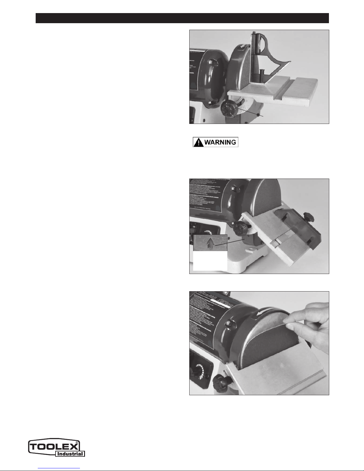
ASSEMBLING THE SANDING DISC TABLE
1. Attach the disc-sanding table (#38) to the sanding
disc guard (#16) by tipping the table up, and slide
the two small nipples extending from the rectangular
mouth of the table, onto the 2 ‘L’ mounting slots in the
sides of the disc sander guide’s frame. FIG. D.
2. Align the two screw holes in the guard with the
arched slots above the angle gauges, so that the
knobs & washers (#39, 95, 94) will travel through the
angle-gauge openings on either side of the disc and
into the mounting holes on the disc sander.
3. Using the disc-table adjustment handles, fasten the
table to the sander.
4. When required for sanding small parts or for sand-
slides in the slot that is in the disc-sanding table.
BELT TABLE ADJUSTMENTS
For most sanding operations, the table will likely
remain at a 90º angle to the belt. A positive stop is
provided with your sander to ensure fast positioning
of the table at 90 degrees to the belt. To ensure and
check the positive-stop 90º angle, proceed as follows:
1. Loosen the table-locking lever / knob (#63).
2. Tilt the table back to the rear as far as possible.
3. Using a square or protractor, measure the angle of
the table against the platen (#84). FIG. E. To adjust
the table angle to ensure a 90º angle, turn the table’s
rear adjustment screw (#61) as needed, and once the
90º is setting is found, lock it in place with the hex nut
(#60), that is under the table.
forward until it is at the required angle. FIG. F.
5. Tighten the table-locking lever to lock the table in
position for sanding.
NOTE: To get the full range of table angling, the
table-locking handle lever must be very loose, so that
it slides along the slot in the table bracket. The table
can then be moved back to get maximum angles.
ASSEMBLY & ADJUSTMENTS
THE MACHINE MUST NOT BE
PLUGGED IN AND THE POWER SWITCH MUST BE
IN THE OFF POSITION UNTIL FULL ASSEMBLY AND
ALL ADJUSTMENTS ARE COMPLETE.
INSTALLING & CHANGING SANDING DISCS
DISC TABLE ADJUSTMENTS
1. To check the trueness of the 90º angle of the
disc-sanding table, place a square or other measur-
ing device on the table with the other end against the
sanding disc. FIG. G.
‘L’ SLOT
TABLE TILT
ANGLE
INDICATOR
TABLE
LOCKING
LEVER
TABLE
ADJUSTING
SCREW
TABLE
LOCKING
LEVER
PLATEN
BEHIND
THE BELT
BRACKET
& SLOT
Note: Not Actual Toolex Product Pictured below
Page 10
10
CHANGING THE SANDING DISC
NOTE: Sanding discs with pressure ensitive adhesive
The sandpaper disc can be removed with the table
installed or with the table removed to give more work
(PSA) backing cannot be used with this sander! Only
Hook & Loop sanding discs can be used.
-
ing access to the disc, if needed.
DISC CHANGING WITH THE TABLE REMOVED:
1. Remove and set aside the miter gauge.
2. Completely remove the 2 disc-table adjustment
handles and washers (#39, 95, 94).
3. Tip the table up and remove it from the guard frame
by slipping the table back out of the slots in the guard.
4. Remove the old disc paper,peel the protective
backing from new sanding disc. Align perimeter of
disc with sanding plate and press disc firmly into
position all the way around. FIG. I.
FIG. G
FIG. H
FIG. I
ADJUSTMENTS
THE MACHINE MUST NOT BE
PLUGGED IN AND THE POWER SWITCH MUST BE
IN THE OFF POSITION UNTIL FULL ASSEMBLY AND
ALL ADJUSTMENTS ARE COMPLETE.
ADJUSTMENT HANDLE
& TABLE ANGLE GAUGE
DISC TABLE ADJUSTMENTS - continued
2. Loosen the 2 disc-table adjustment handles (#39),
and adjust table angle to 90º.
3. Re-tighten the 2 disc-table adjustment handles.
4. To adjust the disc-table to another angle, loosen
the 2 disc-table adjustment handles.
5. Set the table at the desired angle. FIG. H.
6. Re-tighten the 2 disc-table adjustment handles.
TABLE
ANGLE
INDICATOR
Note: Not Actual Toolex Product Pictured below

Page 11
11
INSTALLING & CHANGING SANDING BELTS
SANDING BELT REMOVAL:
1. Remove the top lock-knob (#52), clear plastic belt
guard (#53), and three Phillips screws (#37) that
secure the side cover (#54) to the sander’s frame.
2. Remove the side cover.
3. Push the tracking knob forward release the
belt tension. FIG. J.
4. Remove the belt from the three wheels.
SANDING BELT INSTALLATION:
5. Install the new belt around the top wheel, the large
drive wheel, and then the rear idler wheel.
NOTE: the whole spring-loaded tracking knob assem-
bly can be moved/pulled forward to assist in installing
the belt over the last rear idler wheel.
6. Replace the side cover and re-install the 3 Phillips
screws, clear top guard and lock-knob.
7. Before using, check the belt tracking as described
in “Belt Tracking” section, and adjust as necessary.
FIG. J
FIG. K
Never walk away from sander
when machine is running. Always lock the switch in
the ‘OFF’ position and unplug from the power supply
when not in use.
ADJUSTMENTS
THE MACHINE MUST NOT BE
PLUGGED IN AND THE POWER SWITCH MUST BE IN
THE OFF POSITION UNTIL FULL ASSEMBLY AND ALL
ADJUSTMENTS ARE COMPLETE.
BELT SANDER PLATEN
The platen (# 84) is a heavy steel support plate that
is positioned behind the sanding belt, rising from
the table level to a point several inches above the
table surface. Its purpose is to support the belt when
sanding. The platen should be adjusted so that it is
almost touching the back of the sanding belt. This can
be done by loosening the two hex screws (#86) that
fasten the bottom of the platen to the sander frame. If
the platen is out of alignment for some reason, loosen
these two screws, adjust the platen, and re-tighten the
two screws. FIG. K.
To remove the platen for operations such as curved
surface sanding, stropping, polishing or other special
operations, remove the two screws that fasten the
bottom of the platen to the frame, and remove the
platen.
BELT TRACKING
The belt-tracking adjustment is set at the factory so
that the abrasive belt will run true on the pulleys. If,
however, the belt should track to one side or the oth-
er, an adjustment can be made by turning the tracking
knob (#80), which is located on the back side of the
machine. FIG. J.
- Turning the knob clockwise will cause the belt to
track to the right, towards the sander’s frame.
- Turning the knob counterclockwise will cause the
belt to track to the left, towards the side guard.
TRACKING
KNOB
DRIVE
WHEEL
PLATEN
PLATEN
SIDE GUARD COVER AND
TOP CLEAR GUARD ARE
REMOVED TO
CHANGE A BELT
Note: Not Actual Toolex Product Pictured below
Page 12
FIG. M
DUST
PORT
DUST PORT
12
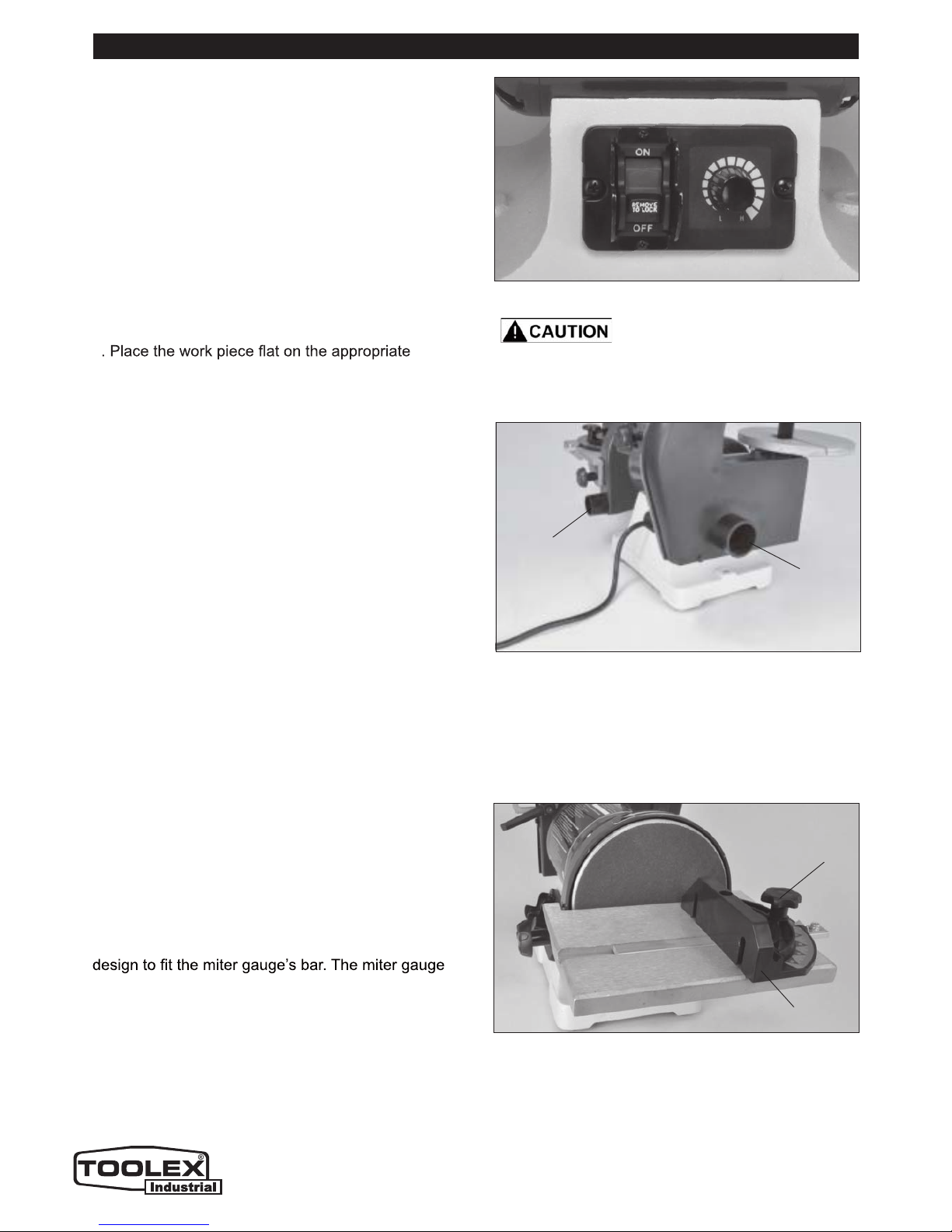
ON/OFF & VARIABLE SPEED SWITCHES
1. To start the machine, the Power Switch must be
in the “OFF” position and the Variable Speed Switch
must be turned to its slowest setting by being turned
all the way to the left until solid resistance is felt. FIG. L.
2. Stand to the side of the sander and plug in
the power cord to a suitable power source.
3. Remain to the side of the sander and turn it
“ON” by moving the power switch to the up position.
4. Allow the sander to come up to a steady speed for
at least one minute. The disc and belt RPM speed
can then be increased to the desired speed for
cleaning operation by rotating
Switch clockwise.
the Variable Speed
table for the desired operation. Firmly hold onto the
work piece.
work
6. When turning the sander OFF, also turn the
Variable Speed Dial counterclockwise to return the
sander to its slowest RPM setting.
7. Unplug the sadner from the power source.
5
NOTE: To prevent unauthorized use of the sander,
the power switch has a removable locking key.
With the power switch in the “OFF” position, pull
the locking key out. The sander machine cannot be
turned “ON” with the key removed. Insert the locking
key to resume sanding operations.
GENERAL USAGE
FIG. N
MITER GAUGE
A miter gauge is supplied with your sander, and can
be used on the disc table, which has a slot in its
head can be set anywhere up to 45º (right or left) by
loosening the lock-knob, setting the miter gauge head
to the desired angle and re-tightening the lock-knob.
FIG. N.
DUST CHUTES / PORTS
Sanding operations are inherently dusty. To help
minimize the amount of dust that escapes into the
surrounding air, this sander is equipped with two dust
chutes (aka: ports) that can be easily connected to a
dust-collection system. FIG. M.
There is one dust chute for the belt-sanding system
and another for the disc-sanding system. Attach your
dust collector to the proper dust chute according to
which sanding mode (belt or disc) is being used.
NOTE: It is strongly recommended that users
employ a dust-collection system when using this
belt & disc sander. Use of a mask or respirator is still
recommended, even when a dust-collection system
is in use.
Never start the machine with work
in contact with the sanding belt or disk, or damage
to the machine, your project, or personal injury may
result from the sudden ‘kick-back’ of the parts.
MITER
GAUGE
FIG. L
LOCK
KNOB
Note: Not Actual Toolex Product Pictured below

Page 13
13
TROUBLESHOOTING
SYMPTOM PROBABLE CAUSE CORRECTIVE ACTION
Motor will not start. 1. Low voltage
2. Open circuit in motor or loose
connections.
3.
4.
Blown fuse or breaker.
Low temperature
1. Start the motor at high speed.
2. Inspect all lead connections on motor
for loose or open connections. (Send
for Servicing.)
3. Short circuit. (Send for Servicing.)
4. Improper match between tool and
circuit, fuse or breaker.
Motor will not start – fuses
or circuit breakers tripping
or blowing.
1. Short circuit in line, cord or
plug.
2. Short circuit in motor or loose
connections.
3. Incorrect fuses or circuit break-
ers in power line.
1. Inspect cord or plug for damaged in-
sulation and shorted wires.
2. Inspect all connections on motor for
loose or shorted terminals and/or worn
insulation.
3. Install correct fuses or circuit breakers
or switch tool to an appropriately sized
circuit.
Motor overheats. 4. Motor is overloaded.
5. Extension cord is too long and
6. Poor air circulation around the
motor
4. Reduce load on motor (pressure on
the sandpaper from the object being
sanded.)
5. Utilize an extension cord of appropriate
gauge and length or plug tool directly
into outlet.
6. Reduce the motor run time.
Motor stalls or runs slow -
resulting in blown fuses or
tripped circuit.
1. Motor is overloaded.
2. Short circuit in the motor or
loose connections.
3. Low line voltage.
4. Incorrect fuses or circuit break-
ers in the power line.
5. Motor capacitor has failed.
6. Belt tension is too tight.
1. Reduce the load on the motor.
2. Inspect connections on motor for loose
or shorted terminals or worn insulation.
3. Correct low voltage conditions (for ex-
ample: improper extension cord length
and/or wire gauge).
4. Install CORRECT fuses or circuit
breakers or plug tool into an appropri-
ate circuit, matched to an appropriate
fuse or breaker.
5. Replace motor capacitor.
6. Decrease belt tension.
Machine slows down when
operating.
1. Feed rate is too great.
2. Undersized circuit or use of
undersized extension cord.
1. Reduce the rate at which the work is
fed into the sandpaper.
2. Ensure circuit wires or extension cords
are proper gauge, or eliminate use of
extension cords.
Machine vibrates
excessively or makes
excess noise.
1. Incorrect motor mounting.
2. Incorrect sanding-belt tension.
3. Weak or broken belt tension
spring.
4. Idler roller is too loose.
5. Broken/defective sanding belt
or disc.
6. Drive belt is too tight
1. Make sure all fasteners are tightened.
2. Adjust tension-adjustment knob.
Follow belt tensioning/tracking instruc-
tions in this manual.
3. Replace belt tension spring by service
technician.
4. Have service technician adjust idler
roller.
5. Replace sanding belt/disc.
6. Decrease belt tension.

Page 14
4
TROUBLESHOOTING
MAINTENANCE REQUIRED FREQUENCY
&KHFNWKHSRZHUFRUGIRUDQ\GDPDJH %HIRUHHDFKXVH
&KHFNVDQGLQJEHOWVDQGGLVFVIRUGDPDJH %HIRUHHDFKXVH
&KHFNDOOJXDUGVDQGKDUGZDUHWRPDNHVXUHWKH\DUHVHFXUH %HIRUHHDFKXVH
&KHFNDOOPRYLQJSDUWVIRUDOLJQPHQWDQGELQGLQJLVVXHV %HIRUHHDFKXVH
'UHVV&OHDQVDQGLQJVXUIDFHVIRUEHVWDEUDVLYHDFWLRQ $VQHHGHG
5HSODFHVDQGLQJEHOWVRUGLVFVZKHQZRUQRUGDPDJHG $VQHHGHG
&OHDQDQGYDFXXPGXVWIURPWKHPRWRUKRXVLQJDQGRWKHUVDQGHUSDUWV $VQHHGHG
Service beyond recommended maintenance on these tools should only be performed by an
DXWKRUL]HGTXDOL¿HGWHFKQLFLDQ
7XUQWKHSRZHUVZLWFK³2))´DQGGLVFRQQHFWWKHSOXJIURPWKHRXWOHWSULRUWRDGMXVWLQJRU
PDLQWDLQLQJWKHVDQGHU'2127DWWHPSWWRUHSDLURUPDLQWDLQWKHHOHFWULFDOFRPSRQHQWVRIWKHPRWRU7DNHWKH
VDQGHUWRDTXDOL¿HGVHUYLFHWHFKQLFLDQIRUWKLVW\SHRIPDLQWHQDQFH
MAINTENANCE
SYMPTOM PROBABLE CAUSE CORRECTIVE ACTION
%XUQPDUNVRQZRUNSLHFH 8VLQJDVDQGLQJJULWWKDWLVWRR
¿QH
8VLQJWRRPXFKSUHVVXUH
:RUNKHOGVWLOOIRUWRRORQJ
DJDLQVWWKHVDQGSDSHU
8VHDFRDUVHUJULWVDQGSDSHU
5HGXFHZRUNSLHFHSUHVVXUHRQ
WKHVDQGSDSHUZKLOHVDQGLQJ
'RQRWNHHSWKHZRUNSLHFHVDQG
LQJLQRQHSODFHIRUWRRORQJ
'HHSVDQGLQJJURRYHVRU
VFDUVLQZRUNSLHFH
6DQGLQJEHOWGLVFJULWLVWRR
FRDUVHIRUWKHGHVLUHG¿QLVK
:RUNSLHFHLVEHLQJVDQGHG
DFURVVWKHJUDLQ
7RRPXFKVDQGLQJIRUFHRQWKH
ZRUNSLHFH
:RUNSLHFHKHOGVWLOODJDLQVWWKH
EHOWGLVFIRUWRRORQJ
8VHD¿QHUJULWVDQGLQJEHOWRU
GLVF
6DQGZLWKWKHJUDLQRIWKHZRRG
5HGXFHSUHVVXUHRQZRUNSLHFH
ZKLOHVDQGLQJ
.HHSZRUNSLHFHPRYLQJZKLOH
VDQGLQJ
6DQGLQJVXUIDFHFORJV
TXLFNO\
7RRPXFKSUHVVXUHDJDLQVWWKH
EHOWRUGLVF
6DQGLQJVRIWZRRGRUKLJKO\
UHVLQRXVZRRGV
5HGXFHSUHVVXUHRQZRUNSLHFH
ZKLOHVDQGLQJ
8VHGLႇHUHQWVWRFNVDQGLQJJULWV
RUDFFHSWWKDWWKLVZLOOKDSSHQDQG
SODQRQFOHDQLQJRUUHSODFLQJEHOWV
GLVFVIUHTXHQWO\
6DQGLQJJUDLQVHDVLO\UXE
RႇWKHEHOWRUGLVF
6DQGSDSHUKDVEHHQVWRUHGLQ
DQLQFRUUHFWHQYLURQPHQW
6DQGSDSHUKDVEHHQGDPDJHG
RUIROGHG
(QVXUHVDQGSDSHULVVWRUHG
DZD\IURPH[WUHPHO\KRWGU\
RUGDPSKXPLGFRQGLWLRQV
6WRUHVDQGLQJDFFHVVRULHVÀDW±
QRWEHQWRUIROGHG
:RUNSLHFHOLIWVXSIURP
WKHVDQGLQJGLVFWDEOH
6DQGLQJRQWKH³XS´ULJKWVLGH
RIWKHGLVFZKHUHURWDWLRQLVXS
DQGDZD\IURPWKHWDEOH
6DQGRQOHIWVLGHRIVDQGLQJGLVF
ZKHUHWKHGLVFURWDWHVGRZQ
WRZDUGVWKHWDEOH

Page 15
PARTS DIAGRAM
15

Page 16
PARTS LIST
16
DESCRIPTION
KEY
NO. QTY. DESCRIPTION
KEY
NO. QTY.
3KLOOLSVVFUHZELJIODWZDVKHU 0;
5XEEHUIRRW
%RWWRPSODWH
&LUFXLWERDUG
3KLOOLSVVFUHZ67[
&LUFXLWERDUGER[
+H[EROWVSULQJZDVKHU0[
+H[VFUHZ0
+H[VFUHZ0
3KLOOLSVVFUHZ 0;
&RUGIL[LQJSODWH
3KLOOLSVVFUHZ6SULQJZDVKHUIODWZDVKHU 0;
&DSDFLWRU
%DVH
&RUGFOLS
'LVFJXDUG
3KLOOLSVVFUHZ6SULQJZDVKHUIODWZDVKHU 0;
3KLOOLSVVFUHZ0;
+H[QXW0
)DVWHQLQJVFUHZ
3RZHUFRUG
2XWHUWRRWKHGORFNLQJZDVKHU˳
&RUGEXVKLQJ
3RWHQWLRPHWHU
6ZLWFKSODWH
3KLOOLSVVFUHZ0;
5XEEHUZDVKHU
+H[VFUHZ
9DULDEOHVSHHGNQRE
6ZLWFKFRYHU
3KLOOLSVVFUHZ0[
/RFNLQJVZLWFK
$OXPLQXPGLVF
+H[VFUHZZDVKHU0;
6DQGSDSHUGLVFJULW PP
'LVFFRYHU
3KLOOLSVVFUHZIODWZDVKHU 0;
:RUNWDEOH
:RUNWDEOHORFNLQJNQRE
3KLOOLSVVFUHZIODWZDVKHU 0[
/HIWHQGFDS
:DY\ZDVKHU'
%DOOEHDULQJ5=
6WDWRU
5RWRU
5LJKWHQGFDS
)HHGEDFNOLQH
3KLOOLSVVFUHZ0;
)HHGEDFNSODWH
+H[VFUHZ0[
5LJKWJXDUGFRYHU
/RFNLQJNQRE
%HOWFRYHU
%HOWVXSSRUWFRYHU
6DQGLQJ%HOWJULW
3KLOOLSVVFUHZORFNZDVKHU 0;
'ULYHZKHHO
+H[QXW0
%HOWVXSSRUW
+H[QXW0
+H[VFUHZ0;
%HOWZRUNWDEOH
/RFNLQJNQRE
%LJIODWZDVKHU ˳
3KLOOLSVVFUHZ 0;
+H[VFUHZ0;
,GOHUVKDIW
:DVKHUIRUVKDIW˳
%DOOEHDULQJ5=
,GOHUSXOOH\
+H[EROW0;
$GMXVWLQJFRYHU
2SHQLQJZDVKHU˳
)ODWZDVKHU˳
$GMXVWLQJVSULQJ,,
$GMXVWLQJ)L[LQJSODWH
6SULQJSLQ;
3KLOOLSVVFUHZ67;
$GMXVWLQJVSULQJ,
$GMXVWLQJKDQGOH
$GMXVWLQJVSULQJ
/RFNLQJQXW0
$GMXVWLQJVKDIW
%HOWZRUNUHVW
)ODWZDVKHU˳
+H[EROW0;
%HOWJXDUGSODWH
%LJIODWZDVKHU ˳
0LWHUJDXJHNQRE
3KLOOLSVVFUHZ6SULQJZDVKHUIODWZDVKHU0;
0LWHUJDXJHSRLQWHU
6OLGHEDU
0LWHUJDXJH
)ODWZDVKHU˳
6SULQJZDVKHU˳
+H[ZUHQFK
&RUGSODWH
&RUGVXESODWH
%LJIODWZDVKHU ˳
/RFNQXW 0
Table of contents


