Toona TO4005 User manual

Toona
EN - Instructions and warnings for installation and use
Swing gate opener
series 4
series 5
series 7


EN
English – 1
ENGLISH
Safety warnings
•CAUTION! - This manual contains important instructions and warnings
for personal safety. Wrong installation can cause serious injuries. Before
starting work read all the manual carefully. If in doubt, stop installation and
ask the Nice Assistance Department for clarifications.
•CAUTION! – According to the most recent European legislation, the
realisation of an automatic door or gate must comply with the regula-
tions of Directive 98/37/CE (Machine Directive) and in particular, stan-
dards EN 12445; EN 12543; EN 12635 and EN 13214-1, which declare
the presumed conformity of the automation. In consideration of this,
all the installation, connection, inspection and maintenance operations
of the product must be performed exclusively by a qualified and com-
petent technician!
•CAUTION! – Important instructions: keep this manual for any possible
future requirement for maintenance and disposal of the product.
Warnings for installation
• Before installing check if this product is suited to automating your gate or
door (see chapter 3 and “Technical features of the product”). If unsuitable,
DO NOT proceed with the installation.
• Include a disconnection device in the power supply system with an opening
distance between the contacts to permit full disconnection in the conditions
dictated by the category of surcharge III.
•All the installation and maintenance operations must occur with the
automation disconnected from the electrical power supply. If the discon-
nection device of the power supply is not visible from the area where the
automatism is located, before starting the work it is necessary to attach a
sign with the text “CAUTION! MAINTENANCE IN PROGRESS” on the dis-
connection device.
• During installation handle the automatism with care avoiding crushing,
knocks, falls or contact with liquids of any kind. Do not place the product
near sources of heat, or expose it to naked flames. All these activities can
damage and cause malfunctions or dangerous situations. If this occurs, stop
the installation immediately and contact the Nice Assistance Department.
• Do not make alterations to any part of the product. Operations which are not
permitted will cause only malfunctions. The manufacturer declines any liabili-
ty for damage caused by arbitrary alterations to the product.
• If the gate or the door to be automated is fitted with a pedestrian door it is
necessary to include a control system in the installation to prevent the opera-
tion of the motor when the pedestrian door is open.
• Check there are no trapping points towards fixed parts when the leaf of the
gate is in the maximum Open position, if necessary protect these parts.
• The push button control on the wall must be positioned in sight of the
automation, away from the moving parts, at a minimum height of 1.5 m from
the ground and it must not be accessible to the public.
• The product packaging material must be disposed of respecting the local
regulations in force.
GENERAL SAFETY WARNINGS AND
PRECAUTIONS
1
This product has been designed to automate gates or doors with leaf opening,
for residential or industrial use. CAUTION! – Any other use different to that
described and in ambient conditions different to those set out in this
manual is to be considered improper and forbidden!
The product is an electromechanical gear motor, equipped with a 24 v continu-
ous current or 230V (depending on the model) alternate current motor and an
endless screw reduction gear.
The gear motor is powered by the external control unit to which it is connected.
In the event of a black out, it is possible to move the gate leaves by hand,
unblocking the gear motor manually.
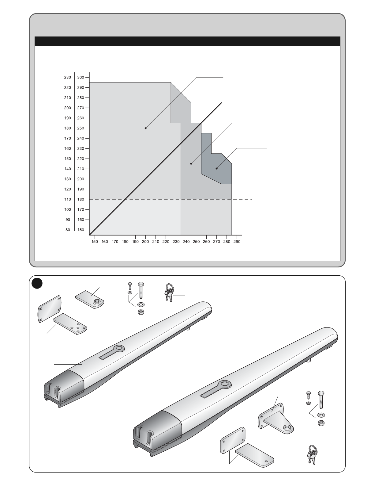
Fig. 1 shows all the components provided in the package (according to the
model chosen):
[a] - electromechanical gear motor
[b] - front bracket (for fixing the gear motor to the gate leaf)
[c] - rear bracket and plate (for fixing the gear motor to the wall)
[d] - metal parts (screws, washers, etc.)
[e] - keys to manually unlock the gear motor
DESCRIPTION OF THE PRODUCT
AND ENVISAGED USE
2
3.1 - Checks before installation
Before installation, check the integrity of the components, suitability of the
model chosen and suitability of the environment chosen for the installation.
IMPORTANT – The gear motor cannot automate a manual gate which
does not have a safe and efficient mechanical structure. Furthermore, it
cannot solve the faults caused by wrong installation or bad maintenance
of the gate itself.
3.2 - Suitability of the gate to being automated and the sur-
rounding environment
• Check the mechanical structure of the gate is suited to being automated and
conforms to the national laws in force (if necessary make reference to the data
on the gate label).
• Moving the gate leaf manually in Open and Close position, check the move-
ment occurs with equal and constant attrition at each point of the stroke (there
must be no moments of greater effort).
• Check the gate leaf remains balanced, that it does not move if brought man-
ually to any position and left stopped.
• Check the space around the gear motor allows to manually unblock the gate
leaf, easily and safely.
• Check the surfaces chosen for installing the product are solid and can guar-
antee stable fixing.
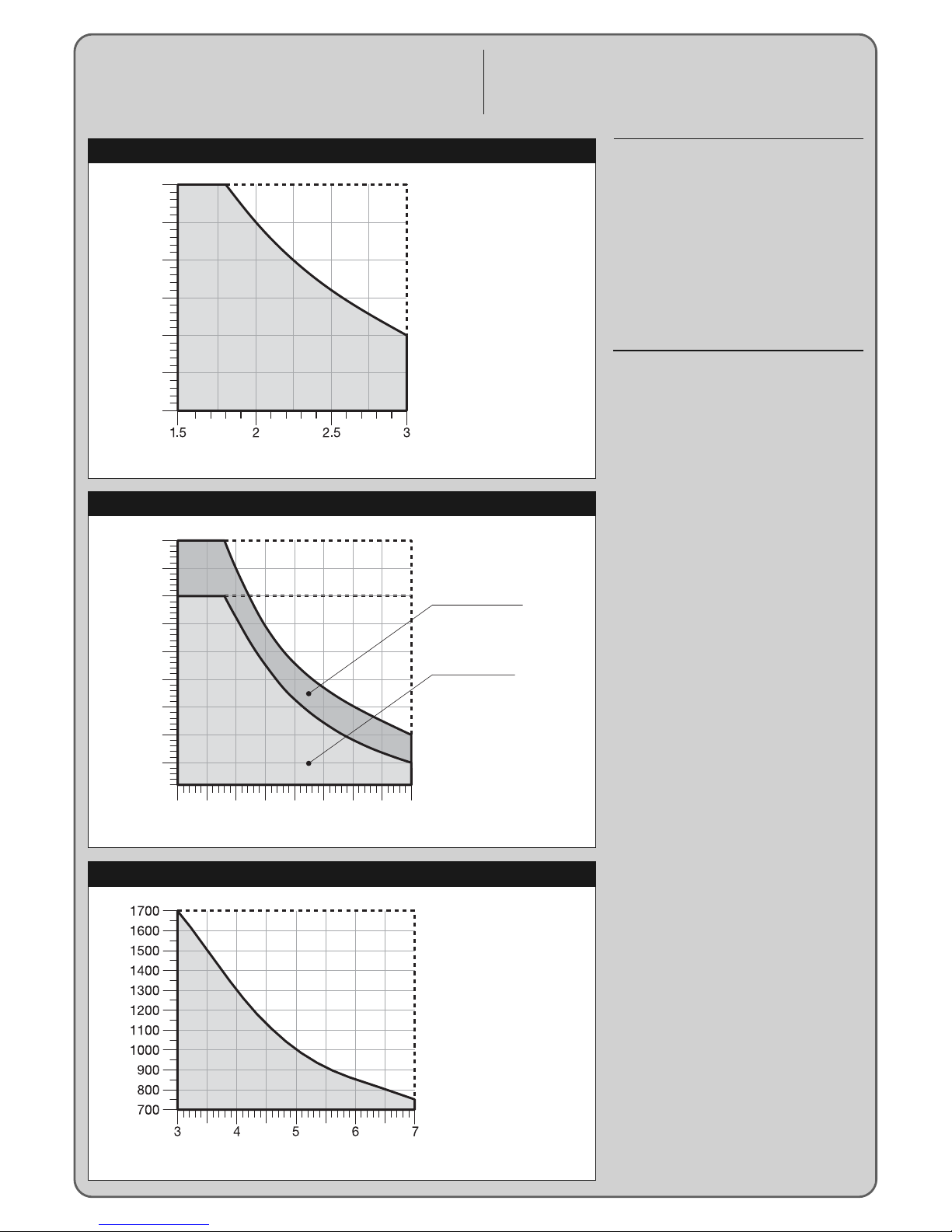
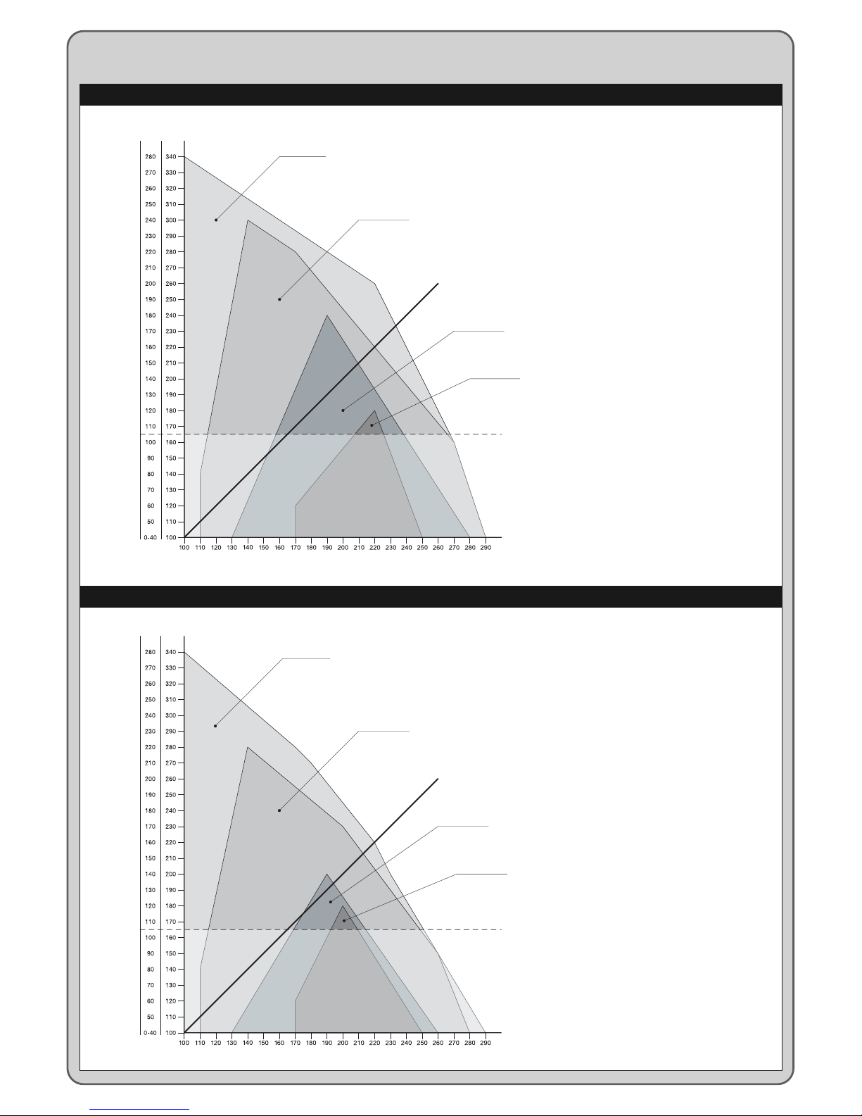
• Check the fixing zone of the gear motor is compatible with the size of the lat-
ter, see fig. 2: the correct Opening movement of the gate and the force the
motor exerts to perform it, depend on the position in which the rear fixing
bracket is secured. Therefore, before installing it is necessary to make reference
to graph 2 to define the maximum Opening angle of the leaf and the force of
the motor, suited to the individual system.
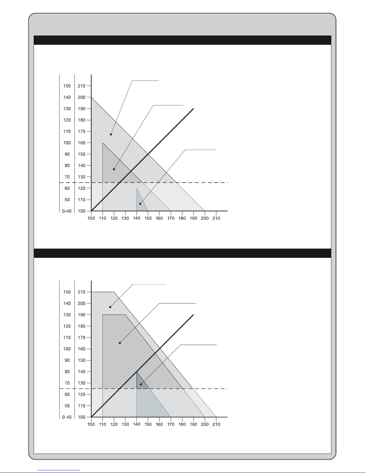
3.3 - Limits of use of the product
Before installing the product, check the gate leaf is the right size and weight
and falls within the limits shown in graph 1.
3.4 - Preparing for installation
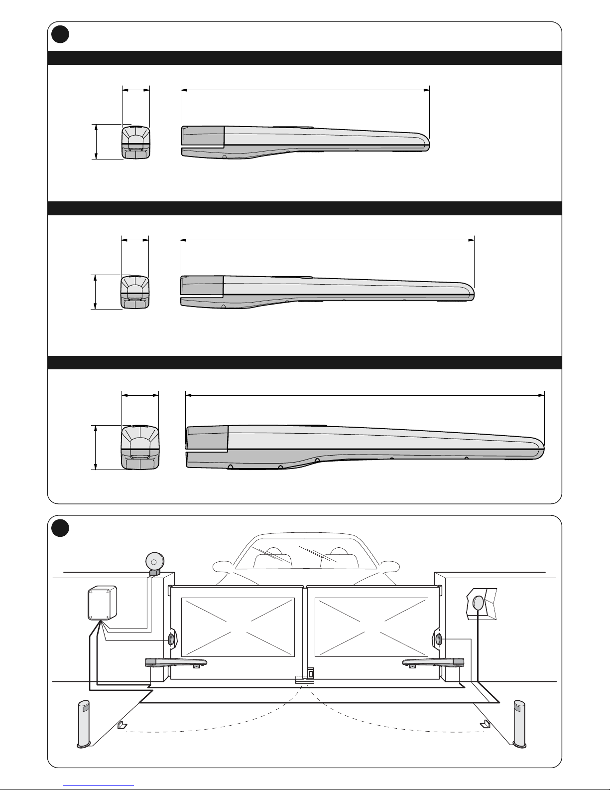
Fig. 3 shows an example of an automation system designed with Nice compo-
nents. These components are positioned according to a typical and usual
scheme.
Making reference to fig. 3, decide the approximate position in which to install
each component envisaged by the system and the most appropriate connec-
tion diagram.
Useful components for producing a complete system (fig. 3):
1- Electromechanical gear motors
2- Couple of photocells
3- Couple of stop blocks (in Opening)
4- Columns for photocells
5- Flashing signalling device with incorporated antenna
6- Key selector switch or digital keypad
7- Vertical electrical locking (only for reversible models)
8- Control unit
INSTALLATION
3

A(mm) E(mm) E(mm) E(mm)
100 630 595 630 630 630 780 745 780 780 780
110 620 585 620 620 620 770 735 770 770 770
120 610 575 610 610 610 760 725 760 760 760
130 600 565 600 600 600 750 715 750 750 750
140 590 555 590 590 590 740 705 740 740 740
150 580 545 580 580 580 730 695 730 730 730
160 570 535 570 570 570 720 685 720 720 720
170 560 525 560 560 560 710 675 710 710 710
180 550 515 550 550 550 700 665 700 700 700 890
190 540 505 540 540 540 690 655 690 690 690 880
200 530 495 530 530 530 680 645 680 680 680 870
210 520 485 530 530 530 670 635 670 670 670 860
220 660 625 660 660 660 850
230 650 615 650 650 650 840
240 640 605 640 640 640 830
250 630 595 630 630 630 820
260 620 585 620 620 620 810
270 610 575 610 610 610 800
280 600 565 600 600 600 790
2– English
EN
3.5 - Installation of fixing brackets and gear motor
3.5.1– Installation of rear fixing bracket
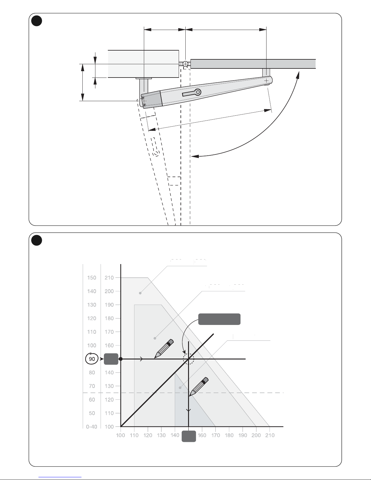
Calculate the position of the rear bracket using graph 2.
This graph serves to establish dimensions A and Band the value of the max-
imum opening angle of the leaf. Important – The values of A and B must
be similar to allow linear movement of the automation.
01. Measure dimension C (fig. 4) on the fixing side;
02. On graph 2, identify dimension C found and trace a horizontal line that
determines the value of dimension B (*) as shown in the example of fig. 5;
the meeting point with line “r.i.l” (installation line recommended) deter-
mines the value of the angle of maximum opening. From this point, trace a
vertical line as shown in the example of fig. 5 to determine the value of
dimension A.
If the angle found does not correspond to the requirements, adapt dimen-
sion A and if necessary dimension B, so they are similar.
(*) Do not use values of dimension B below the line “t” (see graph 2).
03. Before being fixed to the wall the bracket must be sealed to the specific fix-
ing plate (fig. 7); if necessary the bracket can be cut adapting values of
dimensions A and B.
Note – The bracket supplied for the Toona series 4-5 gear motor, meas-
ures 150 mm in length; in the event of special applications or in the event
of a gate equipped with external opening (fig. 6) use bracket mod. PLA6
(accessory).
CAUTION! – Before securing the rear bracket, check the fixing zone
of the front bracket is in a solid part of the leaf, as this bracket must
be fixed at a different height of the rear bracket (fig. 8).
04. At this point, fix the bracket using dowels, screws and washers required
(not supplied).
3.5.2– Installation of front fixing bracket
The front bracket must be fixed to the gate leaf respecting the values of dimen-
sions D and E (Fig. 4).
Note – The bracket supplied for the Toona series 4-5 gear motor must be weld-
ed directly to the gate leaf. If this is not possible, use bracket mod. PLA8
(accessory).
01. Establish the value of dimension E using Table 1;
02. Establish the height in which to position the front bracket, referring to fig. 8;
03. Fix the bracket to the solid part of the gate leaf.
3.5.3– Installation of the gear motor on the fixing brackets
•Installing the gear motor on the rear bracket:
01. Fix the gear motor to the bracket as shown in fig. 9 using the screw,
washer and nut supplied;
02. Tighten the nut to the end and then loosen by 1/10 of a turn to allow min-
imum clearance between the parts.
•Installing the gear motor on the front bracket:
01. Fix the gear motor to the bracket as shown in fig. 10 using the screw,
washer and nut supplied;
02. Tighten the screw to the end.
03. Fix the label provided in the package, dealing with the unblocking and
blocking operations of the gear motor, permanently close to the gear motor
3.6 - Setting the mechanical limit switch
The mechanical limit switch allows to set the stop position of the gate leaf, in
this way, it is not necessary to use the stop blocks and the leaf does not hit
against these at the end of the manoeuvre.
• Toona series 4-5 (24 V)
WARNING – In the event of applications with a gate equipped with open-
ing towards the outside (fig. 6) it is necessary to invert the power supply
wires. Set the limit switch in Opening of the gear motor as follows:
01. Unblock the gear motor as shown in fig. 16;
02. Loosen the mechanical stop screw;
03. Bring the gate leaf manually to the Open position required;
04. Then, bring the mechanical stop to the end of the pin and block the screw
(fig. 11).
05. Bring the leaf manually to the Close position and block the gear motor.
Note –Gear motors mod. TO4006 and mod. TO5016, are provided with a
mechanical limit switch also for the Closing manoeuvre. If in possession of
one of these models, to set the mechanical limit switch repeat the procedure
described above, with a variation at point 03, in this case, bring the gate leaf
manually in the required Closing position.
• Toona series 4-5 (230 V)
The Toona series 4-5 gear motors arranged for an alternate current of 230V,
come with mechanical stop with micro switch which, on contact with the pin
interrupts the electrical power supply. WARNING – In the event of applica-
tions with a gate equipped with opening towards the outside (fig. 6) it is
necessary to invert the power supply wires.
• Toona series 7
Set the limit switch in Opening and Closing of the gear motor;
01. Unblock the gear motor as shown in fig. 16;
02. Move the leaf manually until the mechanical stop screw is visible and
loosen the screw;
03. Bring the gate leaf manually to the Open position required;
04. Then, bring the mechanical stop to the end of the pin and block the screw
(fig. 12);
05. At this point repeat this procedure bringing the leaf manually to the position
of maximum Closure, to set the limit switch in Closure;
06. Finally, block the gear motor.
Toona 4 Toona 5 Toona 7
TO4005 TO4006 TO4015 TO4605 TO4024 TO5015 TO5016 TO5605 TO5024 TO5024I TO7024
D(mm): 730 695 730 730 730 880 845 880 880 880 1070
TABLE 1
English – 3
EN
CAUTION!
–A wrong connection can cause faults or danger; therefore follow
scrupulously the connections set out.
–Perform the connection operations when the electricity is off.
To connect the gear motor to the control unit, proceed as follows:
01. Remove the lid of the gear motor as shown in fig. 13;
02. Loosen the cableway of the gear motor and insert the connecting cables
inside it (fig. 14);
03. Connect the various wires and grounding cable, exactly as shown in the
wiring diagram of fig. 15;
04. Replace lid on gear motor.
To check the connections, direction of rotation of the motor, phase shift in the
movement of the leaves and setting the limit switch, refer to the instructions
manual of the control unit.
IMPORTANT – With a gate configured with opening towards the outside invert
the power supply wires with respect to the standard installation.
ELECTRICAL CONNECTIONS
4
This is the most important phase in realising the automation to guarantee max-
imum safety. The inspection can be used also to periodically check the devices
which make up the automatism.
The inspection of the entire system must be performed by expert and
qualified staff who must take responsibility of the tests requested, depending
on the risk involved and to check compliance of what is set out by laws, rules
and regulations and in particular all the requirements of regulation EN 12445
which establishes the testing methods to verify gate automatisms.
Inspection
Each single component of the automatism, for example sensitive edges, photo-
cells, emergency shutdowns, etc. requires a specific inspection phase; for
these devices follow the procedures shown in the respective instruction manu-
als. For inspection of the gear motor follow the operations below:
01. Check that everything in this manual and in particular in chapter 1 has
been rigorously complied with;
02. Unblock the gear motor as shown in fig. 16;
03. Check it is possible to manually move the leaf when opening and closing
with a force no greater than 390N (approx. 40 kg);
04. Block the gear motor and connect the electrical power supply;
05. Using the control or shutdown devices envisaged (key selector switch,
control buttons or radio transmitters), perform a number of opening, clos-
ing and stopping tests of the gate and check it behaves as it should;
06. Check the correct operation of all the safety devices one by one in the sys-
tem (photocells, sensitive edges, emergency shutdown, etc.) and check
the gate behaves as it should;
07. Command a closing manoeuvre and check the force of the impact of the
leaf against the end of the mechanical limit switch. If necessary, try to
unload the pressure, finding a setting which gives better results;
08. If the dangerous situations caused by the movement of the leaf have been
protected by limiting the force of impact the force must be measured as
required by regulation EN 12445;
Note – The gear motor is not provided with torque setting devices, such regu-
lations are done by the Control unit.
Putting into operation
This can occur only after having performed, with positive results, all the inspec-
tion phases of the gear motor and other devices present. To put it into opera-
tion refer to the instructions manual of the control unit.
IMPORTANT – It is forbidden to put into partial or provisional operation.
INSPECTING THE AUTOMATION
5DISPOSAL OF THE PRODUCT
This product is an integral part of the automation, and therefore, they
must be disposed of together.
As for the installation operations, at the end of the life of this product, the dis-
mantling operations must be performed by qualified personnel.
This product is made from different types of materials: some can be recycled,
others must be disposed of. Please inform yourselves on the recycling or dis-
posal systems provided for by the laws in force in your area, for this category of
product.
CAUTION! – some parts of the product can contain polluting or dangerous
substances which, if dispersed in the environment, may cause serious harm to
the environment and human health.
As indicated by the symbol at the side, it is forbidden to throw
this product into domestic refuse. Therefore, follow the “sepa-
rated collection” instructions for disposal, according to the
methods provided for by local regulations in force, or redeliver
the product to the retailer at the moment of purchase of a new,
equivalent product.
CAUTION! – the regulations in force at local level may envisage heavy sanc-
tions in case of abusive disposal of this product.
To keep the level of safety consistent and to guarantee maximum life of the
entire automation it is necessary to maintain it regularly.
The maintenance must be performed in line with the safety instructions of this
manual and according to what is set out by the laws and regulations in force.
For the gear motor a programmed maintenance within no more than 6 months
is required.
Maintenance operations:
01. Disconnect any sources of electricity.
02. Check the status of deterioration of all the materials which make up the
automation with particular attention to signs of erosion or oxidation of the
structural parts: replace the parts which do not provide sufficient guaran-
tees.
03. Check the screw connections are sufficiently tight.
04. Check the bolt and endless screw are suitably greased.
05. Check the wear of the moving parts and, if necessary, replace used parts.
06. Reconnect the sources of electrical power and perform all the tests and
checks envisaged in chapter 5.
For the other devices present in the system refer to the individual instruction
manuals.
PRODUCT MAINTENANCE
6
EN
4– English
Toona series 5
Type electromechanical gear motor for gates or doors with leaf opening
Power input 230 Vac 50 Hz 230 Vac 50 Hz 230 Vac 50 Hz 24 Vdc 24 Vdc
Maximum absorption 1,5 A 1,5 A 1,3 A 5 A 5 A
Nominal absorption 1 A 1 A 0,9 A 2 A 2,2 A
Maximum absorbed 340 W 340 W 300 W 120 W 120 W
power
Nominal absorbed 180 W 180 W 160 W 48 W 60 W
power
Capacitor incorporated 7 µF 7 µF 7 µF - -
Protection grade IP 44 IP 44 IP 44 IP 44 IP 44
Travel 540 mm 505 mm 540 mm 540 mm 540 mm
Speed loadless 0,013 m/sec 0,013 m/sec 0,016 m/sec 0,016 m/sec 0,013 m/sec
Speed loaded 0,010 m/sec 0,010 m/sec 0,012 m/sec 0,012 m/sec 0,010 m/sec
Maximum force 1800 N 1800 N 1800 N 1800 N 2200 N
Nominal force 600 N 600 N 600 N 600 N 800 N
Operating -20 °C to +50 °C -20 °C to +50 °C -20 °C to +50 °C -20 °C to +50 °C -20 °C to +50 °C
temperature
Thermal protection 140 °C 140 °C 140 °C - -
Cycles/h at nominal force 54 54 50 95 75
Durability estimated between 80,000 and 250,000 cycles of manoeuvres according to the conditions set out in Table 2
Insulation class FFFFF
Dimensions (mm) 965 x 115 x 105 h 965 x 115 x 105 h 965 x 115 x 105 h 965 x 115 x 105 h 965 x 115 x 105 h
Weight 7 Kg 7 Kg 7 Kg 7 Kg 8 Kg
TO5015 TO5016 TO5605 TO5024 TO5024I
TECHNICAL FEATURES OF THE PRODUCT
CAUTIONS: • The technical features set out refer to an ambient temperature of 20°C (± 5°C). • Nice S.p.a. reserves the right to make alterations to the product
any time it deems it necessary, keeping the same functionality and destination of use.
Toona series 4
Type electromechanical gear motor for gates or doors with leaf opening
Power input 230 Vac 50 Hz 230 Vac 50 Hz 230 Vac 50 Hz 230 Vac 50 Hz 24 Vdc
Maximum absorption 1.5 A 1.5 A 1.5 A 1.3 A 5 A
Nominal absorption 1 A 1 A 1 A 0,9 A 2 A
Maximum absorbed power 340 W 340 W 340 W 300 W 120 W
Nominal absorbed power 180 W 180 W 180 W 160 W 48 W
Capacitor incorporated 7 µF 7 µF 7 µF 7 µF -
Protection grade IP 44 IP 44 IP 44 IP 44 IP 44
Travel 385 mm 350 mm 385 mm 385 mm 385 mm
Speed loadless 0.016 m/sec 0.016 m/sec 0.013 m/sec 0.016 m/sec 0.016 m/sec
Speed loaded 0,012 m/sec 0,012 m/sec 0,010 m/sec 0,012 m/sec 0,012 m/sec
Maximum force 1800 N 1800 N 1800 N 1800 N 1800 N
Nominal force 600 N 600 N 600 N 600 N 600 N
Operating temperature -20 °C to +50 °C -20 °C to +50 °C -20 °C to +50 °C -20 °C to +50 °C -20 °C to +50 °C
Thermal protection 140 °C 140 °C 140 °C 140 °C -
Cycles/h at nominal force 58 58 54 50 95
Durability estimated between 80,000 and 250,000 cycles of manoeuvres according to the conditions set out in Table 2
Insulation class FFFFF
Dimensions (mm) 820 x 115 x 105 h 820 x 115 x 105 h 820 x 115 x 105 h 820 x 115 x 105 h 820 x 115 x 105 h
Weight 6 Kg 6 Kg 6 Kg 6 Kg 6 Kg
TO4005 TO4006 TO4015 TO4605 TO4024
EN
English – 5
Toona series 7
Type electromechanical gear motor for gates or doors with leaf opening
Power input 24 Vdc
Maximum absorption 5 A
Nominal absorption 2.5 A
Maximum absorbed power 120 W
Nominal absorbed power 60 W
Protection grade IP 44
Travel 584 mm
Speed loadless 0.013 m/sec
Speed loaded 0.011 m/sec
Maximum force 2700 N
Nominal force 1400 N
Operating temperature -20 °C to +50 °C
Cycles/h at nominal force 41
Durability estimated between 80,000 and 250,000 cycles of manoeuvres according to the conditions set out in Table 2
Insulation class F
Dimensions (mm) 1200 x 128 x 150 h
Weight 15 Kg
TO7024
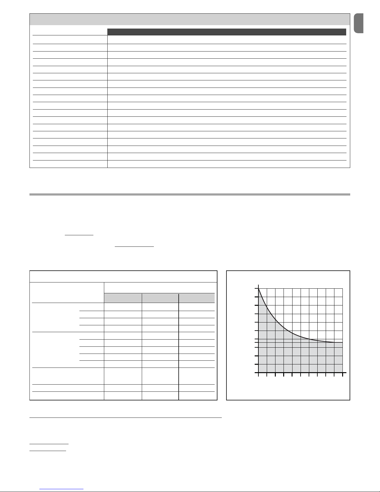
Durability of the product
Durability is the average economic life of the product. The value of durability is strongly influenced by the demand index of the manoeuvres performed by the
automatism: that is the sum of all the factors which contribute to the wear of the product (see Table 2).
To establish the probable durability of your automatism proceed as follows:
01. Calculate the demand index summing the values in percentage of the entries present in Table 2 to each other;
02. In Graph A, from the value just found, trace a vertical line until you intersect the curve; from this point trace a horizontal line to cross the line of “cycles of
manoeuvres”. The value established is the estimated durability of your product.
The estimate of durability is performed on the basis of the design calculations and the results of tests carried out on prototypes. In fact, being an estimate, it does
not give any guarantee on the actual duration of the product.
Example of calculation of durability of a Toona series 5 gear motor (refer to Table 2 and Graph A):
- leaf weight = 350 Kg (demand index= 10%)
- leaf length = 3.5 m (demand index = 10%)
- no other stress elements present
Total demand index = 20%
Durability estimate = 160,000 cycles of manoeuvre
0
0
50.000
80.000
100.000
150.000
200.000
250.000
10 20 30405060708090100
Toona 4 Toona 5 Toona 7
Demand index
> 200 Kg 10 % 0 % 0 %
Leaf weight: > 300 Kg 20 % 10 % 0 %
> 400 Kg 30 % 20 % 10 %
> 500 Kg - 30 % 20 %
2 - 3 m 20 % 0 % 0 %
Leaf 3 - 4 m - 10 % 0 %
length: 4 - 5 m - 20 % 10 %
5 - 6 m - - 20 %
6 - 7 m - - 30 %
Ambient temperature greater
than 40°C or lower than 0°C 20 % 20 % 20 %
or humidity greater than 80%
Blind leaf: 15 % 15 % 15 %
Installation in windy area: 15 % 15 % 15 %
TABLE 2 GRAPH A
Demand index (%)
cycles of manoeuvres

EN
6– English
CE DECLARATION OF CONFORMITY
Note: The content of this declaration corresponds to what is declared in the official document, dated 23rd April 2008, deposited at the premises of Nice
Spa and, specifically, at its last review available before this manual was printed. The text here has been readapted for editorial purposes.
Number: 288/TO Review: 0
The undersigned, Lauro Buoro, in his capacity of Managing Director, declares under his sole responsibility that the product:
Manufacturer: NICE s.p.a.
Address Via Pezza Alta 13, Z.I. Rustignè, 31046 Oderzo (TV) Italia
Type: Electromechanical gear motor TOONA series
Models: TO4005, TO4006, TO4015, TO4024, TO4605, TO5015, TO5016, TO5024, TO5024I, TO5605, TO5624, TO7024
Accessories:
Conforms to the following community directives:
• 98/37/CE (89/392/CEE amended) DIRECTIVE 98/37/CE OF THE EUROPEAN PARLIAMENT AND COUNCIL dated 22nd June 1998 on
the rapprochement of legislations on member States relevant to machines.
As provided for by directive 98/37/CE it is cautioned that it is forbidden to put into operation the product indicated above until the
machine, in which the product is incorporated, has been identified and declared conformant with directive 98/37/CE.
Furthermore, the product conforms to what is provided for by the following community directives, as amended by Directive 93/68/CEE
of the council dated 22nd July 1993:
2006/95/CEE (past directive 73/23/CE) DIRECTIVE 2006/95/CE OF THE EUROPEAN PARLIAMENT AND COUNCIL dated 12th Decem-
ber 2006 concerning rapprochement of the legislations of member states on electrical material for use within certain voltage limits
According to the following harmonised laws: EN 60335-1:1994+A11:1995+A1:1996+A12:1996 +A13:1998+A14:1998+A15:2000
+A2:2000+A16:2001
• 2004/108/CEE(past directive 89/336/CEE) DIRECTIVE 2004/108/CE OF THE EUROPEAN PARLIAMENT AND COUNCIL of 15th
December 2004 concerning rapprochement of the legislations of member states on electromagnetic compatibility and which abrogates
directive 89/336/CEE
According to the following harmonised laws: EN 61000-6-2:2005; EN 61000-6-3:2001+A11:2004
Furthermore, it conforms limited to the applicable parts, to the following standards:
EN 60335-1:2002+A1:2004+A11:2004+A12:2006+ A2:2006, EN 60335-2-103:2003, EN 13241-1:2003; EN 12453:2002;
EN 12445:2002; EN 12978:2003
Oderzo, 23rd April 2008
Lauro Buoro (Managing Director)

ENITFR
ES
DEPL
NL
IX
EN - Images
X
• EN - GRAPH 1 “Limits of use of the product” • IT - GRAFICO 1 “Limiti d’impiego del prodotto”
• FR - GRAPHIQUE 1 “Limites d’utilisation du produit” • ES - GRÁFICO 1 “Límites de empleo del producto”
• DE - GRAPHIK 1 “Verwendungsgrenzen des Produkts” • PL - SCHEMAT 1 “Ograniczenia używania produktu”
• NL - GRAFIEK 1 “Gebruiksbeperkingen van het product”
500
450
400
350
300
250
200
Toona 4
m
Kg
600
550
500
450
400
350
300
250
200
160
1 1.5 2 2.5 3 3.5 4 4.5 5
(mod. 5024)
(mod. 5024I)
m
Kg
m
Kg
Kg:
EN - Maximum weight of the gate leaf
IT - Peso massimo dell’anta del cancello
FR - Poids maximum du vantail du portail
ES - Peso máximo de la hoja de la puerta
DE - Höchstgewicht des Torflügels
PL - Ciężar maksymalny skrzydła bramy
NL - Maximum gewicht van de vleugel
van het hekwerk
m:
EN - Maximum length of the gate leaf
IT - Lunghezza massima dell’anta del
cancello
FR - Longueur maximum du vantail du
portail
ES - Longitud máxima de la hoja de la
puerta
DE - Höchstlänge des Torflügels
PL - Długość maksymalna skrzydła
bramy
NL - Maximum lengte van de vleugel
van het hekwerk
Toona 5
Toona 7
XI
• EN - GRAPH 2 • IT - GRAFICO 2 • FR - GRAPHIQUE 2 • ES - GRÁFICO 2
• DE - GRAPHIK 2 • PL - SCHEMAT 2 • NL - GRAFIEK 2
A (mm)
CB
90° ÷ 100°
100° ÷ 120°
110° ÷ 120°
TO4006
(mm)
A (mm)
CB 90° ÷ 100°
100° ÷ 120°
110° ÷ 120°
TO4005 - TO4015 - TO4024 - TO4605
(mm)
Toona 4
r.i.l.
t
r.i.l.
t
r.i.l. = recommended
installation line
not recommended values area
r.i.l. = recommended
installation line
not recommended values area
XII
• EN - GRAPH 2 • IT - GRAFICO 2 • FR - GRAPHIQUE 2 • ES - GRÁFICO 2
• DE - GRAPHIK 2 • PL - SCHEMAT 2 • NL - GRAFIEK 2
A (mm)
CB
90° ÷ 100°
100° ÷ 110°
110° ÷ 120°
120° ÷ 130°
TO5015 - TO5605 - TO5024 - TO5024I
(mm)
A (mm)
CB
90° ÷ 100°
100° ÷ 110°
110° ÷ 120°
120° ÷ 130°
TO5016
(mm)
r.i.l.
t
Toona 5
r.i.l.
t
r.i.l. = recommended
installation line
not recommended values area
r.i.l. = recommended
installation line
not recommended values area
XIII
1Toona 4-5
Toona 7
• EN - GRAPH 2 • IT - GRAFICO 2 • FR - GRAPHIQUE 2 • ES - GRÁFICO 2
• DE - GRAPHIK 2 • PL - SCHEMAT 2 • NL - GRAFIEK 2 Toona 7
A (mm)
CB
95° ÷ 100°
90° ÷ 95°
(...)° ÷ 90°
TO7024
r.i.l.
t
c
a
b
d
e
a
(mm)
r.i.l. = recommended
installation line
not recommended values area
c
b
d
e
XIV
3
2
Toona 4
Toona 5
Toona 7
115 mm 820 mm
105 mm
115 mm 965 mm
105 mm
128 mm 1200 mm
150 mm
117
2
2
68
44 33
6
XV
A (mm)
CB 90° ÷ 100°
100° ÷ 120°
110° ÷ 120°
90° ÷
1
00°
1
00° ÷
1
20°
1
10° ÷
1
20°
100° ÷ 120°
150
150
5
4AE
D
B
C
(mm)
r.i.l.
not recommended values area

XVI
7
6
D
E
A
B
C

XVII
2
1
9
8
Toona 4-5: F = 44 mm
Toona 7: F = 50 mm
F

XVIII
1
2
3
10
2
3
1
Toona 4-5
Toona 7

XIX
12
11
100 mm max
Toona 4-5
Toona 7

XX
2
1
14
12
13
This manual suits for next models
9
Table of contents
Other Toona Gate Opener manuals


Popular Gate Opener manuals by other brands

CENTURION SYSTEMS
CENTURION SYSTEMS V400 Mechanical Installation Manual

GFA
GFA ELEKTROMAT KE 9.60 FU-25,00 installation instructions

Centurion
Centurion R3 installation manual

Telcoma
Telcoma PASSO CARD Receiver installation instructions

Wholesale
Wholesale SL1694 user manual

Cardin
Cardin 200/BL3924ESB instruction manual


