DKS 1601 User manual

1601/1602 barrier gate operator - installation guide

barrier gate operator installation guide
for use with models
1601-080/081
1602-080/081
with circuit board 1601-010 rev.V or higher
supplemental manual available
(P/N 2340-065) for 1601-081, 1601-088
and 1602-081 for optional battery
backup system with additional wiring
information.
DKS DoorKing, Inc.
120 Glasgow, Avenue
Inglewood, Ca. 90301
310.645.0023
310.641.1586 fax
www.doorking.com
copyright © 2006 DoorKing, Inc.
All rights reserved.
notice of rights
The content in this manual is protected
under copyright law and no portion
of this manual may be copied,
reproduced, translated, or converted
to any electronic medium without prior
written consent.
notice of liability
DoorKing,Inc.reservestherighttomake
changes in the products described
in this manual without notice and/or
obligation to notify any persons of any
revisions or changes. DoorKing, Inc.
makes no representations or warranties
with respect to this manual.
publication number
1601-065-M-05-07
general information
safety information.....................................................................................................4
glossary ........................................................................................................................5
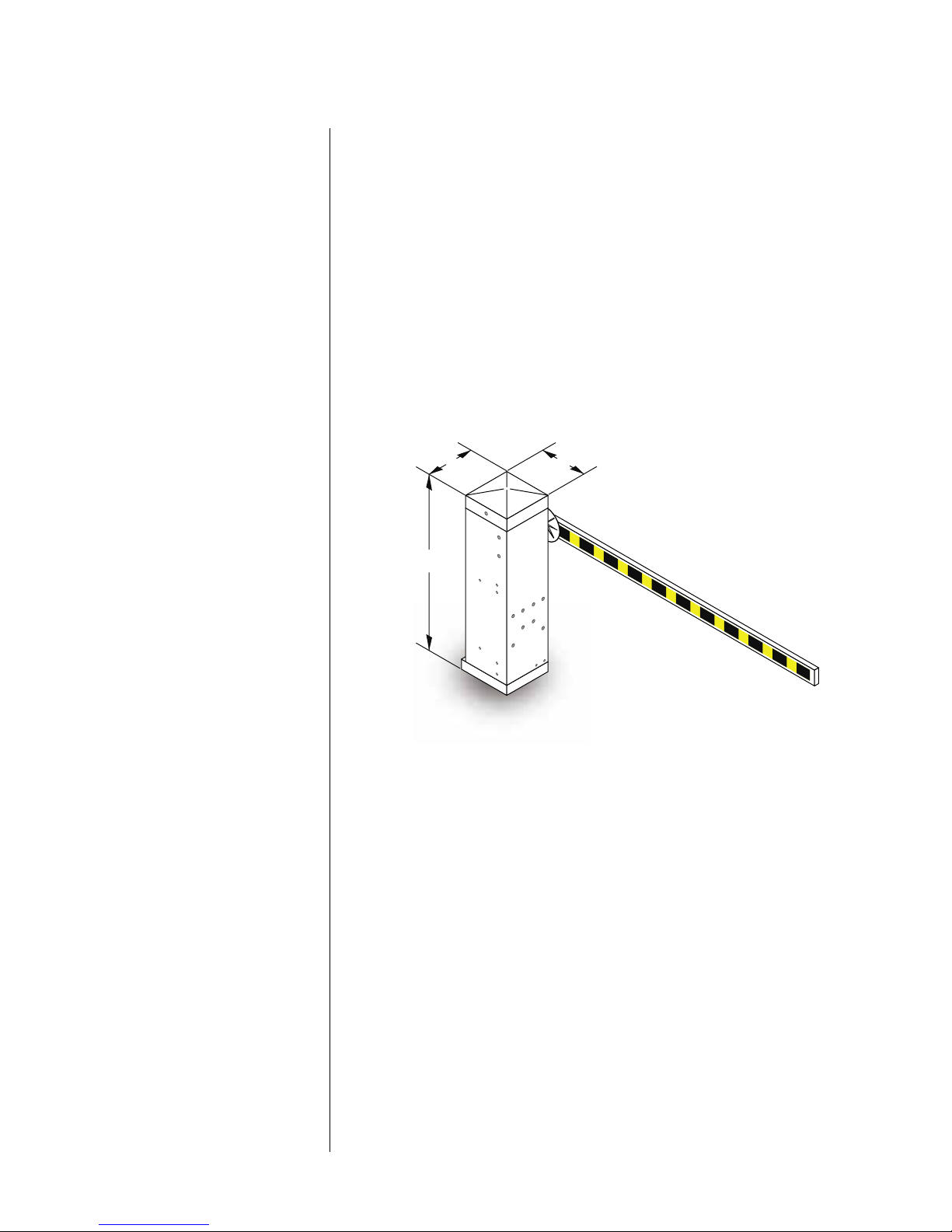
specifications..............................................................................................................6
operator installation
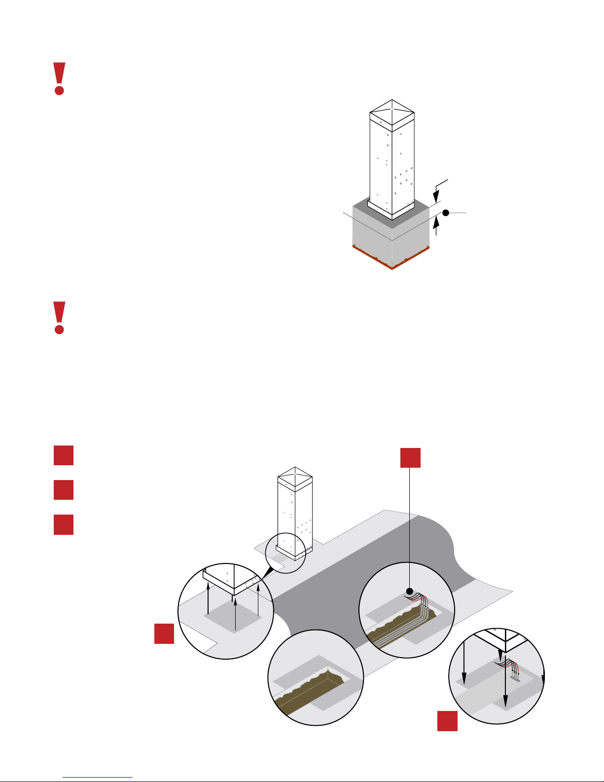
surface operator ........................................................................................................7
electrical installation
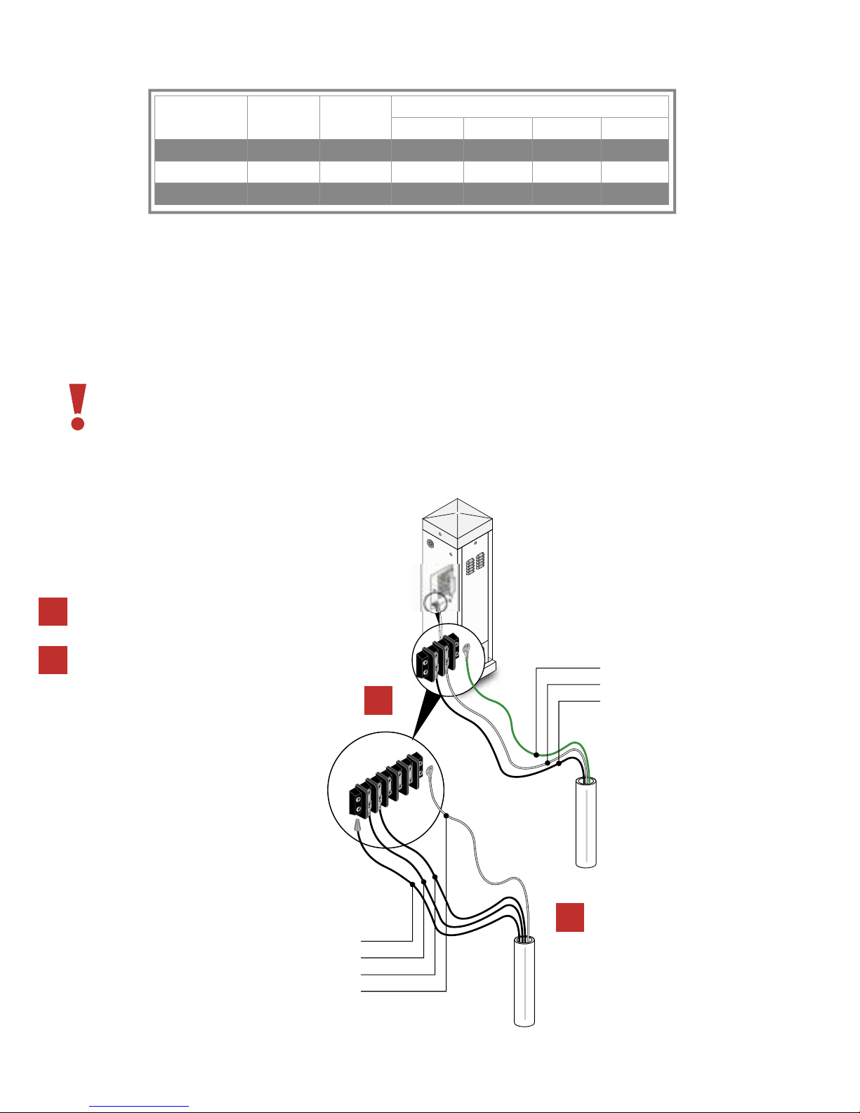
main terminal wiring................................................................................................9
high voltage wiring..................................................................................................10
low voltage wirng ....................................................................................................11
primary/secondary control wiring.......................................................................12
pams wiring ...............................................................................................................13
gate tracker wiring...................................................................................................14
loop detector wiring................................................................................................15
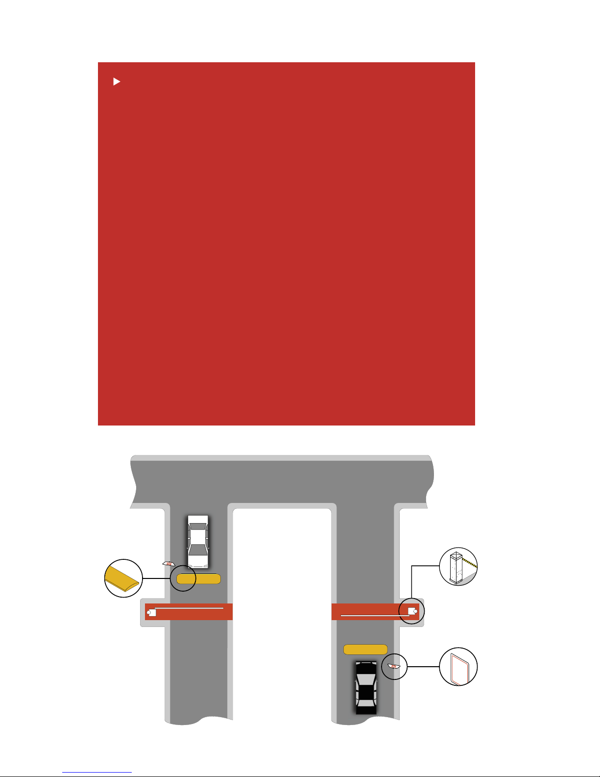
entry lane application.............................................................................................16
exit lane application................................................................................................17
ticket spitter application ........................................................................................18
two-way lane application.......................................................................................19
timer down application..........................................................................................20
arm installation
hub ...............................................................................................................................21
aluminum-plastic-wood .........................................................................................22
wishbone ....................................................................................................................23
settings
control board.............................................................................................................24
magnetic limit ...........................................................................................................25
direction check .........................................................................................................26
reverse sensitivity.....................................................................................................27
switch descriptions & functions ...........................................................................28
accessory installation
reversing edge ..........................................................................................................29
fan kit...........................................................................................................................30
heater kit.....................................................................................................................31
technical information
wiring diagram..........................................................................................................32
wiring diagram-convenience open.....................................................................33
maintenance schedule............................................................................................34
troubleshooting........................................................................................................35
accessories .................................................................................................................36
save this installation guide for reference
1601-065-M-05-07

1601-065-M-05-07
4 installation guide
general information/safety information
SPEED
LIMIT
5
3PEED"UMP
3PEED"UMP
1610
Speed Bumps
Speed Limit
Sign
Operator Danger
Zone
Familiarize yourself with safety warn-
ings, instructions, illustrations, and wiring
guidelines to ensure that the installation is
performed in a safe and professional man-
ner.
Prior to installation check all local build-
ing codes and ordinances to ensure
compliance.
Speed limit through barrier area is 5
MPH. Install speed bumps and warning
signs where visible in the area of the gate,
failure to do so may result in injury, dam-
age to operator and vehicle.
Users should be familiar with proper use
of operator, these include; hardware op-
eration, reversing functions and testing,
reversing loops, inherent reversing system,
electric edges, photoelectric cells related
external devices and possible hazards.
Keep adults, children and objects
away from operator and HAZARD
ZONES. Pedestrians must be provided
with a separate access.
All electrical connections should be made
in accordance with local electrical codes.
Security features should be installed to
avoid unauthorized use.
Controls must be installed away from the
operator (min. 10’ ft. away) to avoid any
contact when operating the controls. If
the installed hardware is in violation of
these restrictions remove the operator
from service immediately and contact
your service dealer.
When removing the operator lift the arm
to the full open position and shut off
power at the service panel.
Operators and components should be
properly installed and maintained fol-
lowing the recommended service sched-
ule, test the operator monthly. Contact
your service dealer for any maintenance
or repairs.
Vehicular operators can produce high
levels of force, it is important that you
are aware and eliminate possible HAZ-
ARDS; Pinch Points, Entrapment, Ab-
sence of Controlled Pedestrian Access,
Traffic Backup.
Reduce the risk of injury or death, read and follow all instructions.

1601-065-M-05-07 installation guide 5
general information/glossary
RESIDENTIAL VEHICULAR OPERATOR-CLASS - A vehicular operator
(or system) intended for use in a home of one-to-four single family dwelling,
garage or parking area associated therewith.
COMMERCIAL / GENERAL ACCESS VEHICULAR OPERATOR-CLASS II -
A vehicular gate operator (or system) intended for use in a commercial location
or building such as a multi-family housing unit (five or more single family units),
hotels, garages, retail store or other building servicing the general public.
INDUSTRIAL / LIMITED ACCESS VEHICULAR OPERATOR-CLASS III - A
vehicular gate operator (or system) intended for use in an industrial location or
building such as a factory or loading dock area or other locations not intended
to service the general public.
RESTRICTED ACCESS VEHICULAR OPERATOR-CLASS IV - A vehicular
gate operator (or system) intended for use in a guarded industrial location or
building such as an airport security area or other restricted access locations
not servicing the general public, were unauthorized access is prevented via
supervision by security personnel.
SYSTEM - In the context of these requirements, a system refers to a group of
interacting devices intended to perform a common function.
WIRED CONTROL - A control implemented in a form of fixed physical
interconnections between the control, associated devices and an operator to
perform predetermined functions in response to input signals.
WIRELESS CONTROL - A control implemented in means other than fixed
physical interconnections (such as radio waves or infrared beams) between
the control, the associated devices and an operator to perform predetermined
functions in response to input signals.
INHERENT ENTRAPMENT SENSOR SYSTEM - An automatic sensor system
that senses entrapment of a solid object and is incorporated as a permanent
and integral part of the operator.
ENTRAPMENT - The condition when an object is caught or held in a position
that increases the risk of injury.

1601-065-M-05-07
6 installation guide
general information/specifications
operator
The 1601 operator has been designed for
high usage single lane (14 feet maximum)
vehicular traffic control.
class:
II, III, IV
horsepower:
1/2 or 1 HP
housing:
G90 galvanized steel, painted white.
mechanical:
worm gear running in a continuous oil bath.
release method:
fail-secure mechanical
operation temperature:
10ºF to 140ºF
-12ºC to 62ºC
voltage:
115/230/460 VAC
note: 230 and 460 VAC units use a
stepdown transformer to achieve 115 VAC
operating voltage.
arm:
wood/aluminum
loop detectors:
Port for plug-in open (up) detector
Port for plug-in reverse (down) detector
DKS Detectors Only
advanced features:
Auto Close Timer 1-23
Electronic Limits
Gate Tracker
Left/Right Mount
safety Listing:
Complies with UL 325 and UL 991 safety
standards.
ETL Listed

1601-065-M-05-07 installation guide 7
hMIN
'2/5.$,%6%,
operator installation/surface operator
Concrete must be even and leveled, avoiding any operator unbalance and unevenness.
Conduit requirements may vary depending on your specific needs. Use only sweeps for conduit bends, do
not use 90° connectors this will make wire pulls very difficult and can cause damage to wire insulation. A
suggested minimum of 3/4-inch conduit should be used. Be sure that all conduits are installed in accor-
dance with local codes.
2
/0%2!4/2
0/3)4)/.
Mix and pour concrete into the trench, al-
low the concrete to cure and place the op-
erator into position.
1
3
From the operator position dig a trench.
NOTE: The trench should enclose the con-
duits.
Run conduits from the operator to their
corrsesponding source .
1
3
•Hi Voltage Conduit
•Low Voltage Conduit
•Loop Lead Conduit
•Sequencing Control or
Primary/Secondary Conduit
2
The operator must be installed on a concrete base. Soil conditions
and local building codes will determine concrete base depth and
width.
•For added support use rebar and/or wire mesh.
•Concrete base should be even and leveled avoiding any
operator unbalance.
•Mix concrete according to manufacturer.
•Pour and tamp concrete into form.
•Level and surface.
•Allow concrete to cure for 48 hrs.

1601-065-M-05-07
8 installation guide
The operator’s access door must
face the opposite side of traffic.
operator installation/surface operator
Place the operator into position and bolt down
using the sleeve anchors.
2
1
3
Set the operator in place and mark the posi-
tion for the sleeve anchors.
Drill the mounting holes (remove all debris),
recommended sleeve anchor sizes are 3/8 x 3
or 1/2 x 3, anchors are not included.
1
2
3

1601-065-M-05-07 installation guide 9
1. 115 VAC NEUTRAL
2. 115 VAC POWER
3. 115 VAC MOTOR POWER
4. 115 VAC MOTOR POWER
5. 24 VAC RADIO RECEIVER POWER ONLY (200 ma. max)
6. UP INPUT - Function is dependent on the setting of programming switch 6. When
switch 6 is OFF, this input will cause the operator to rotate the arm to the up position. If the
arm is in the down cycle, this input will reverse the arm to the up position. If this terminal
has a constant input, the arm will remain in the up position regardless of any down input
or timer command to rotate down. When switch 6 is ON, this input will cause the operator
to rotate the arm to the up position when it is down, and will cause the operator to rotate
the arm to the down position when it is up. If the auto timer is turned ON, this input will
override the timer and rotate the arm to the down position. If the arm is in the down cycle,
this input will reverse the arm to the up position.
7. UP LOOP OUTPUT - Function is dependent on the setting of programming switch
8. When switch 8 is ON, the function of this input is identical to terminal 6 above. When
switch 8 is OFF, this terminal becomes the logic output of the up loop detector.
8. DOWN / REVERSE INPUT - Function is dependent on the setting of programming
switches 1 and 4. With switch 1 OFF and switch 4 ON, activation and then deactivation of
this input will rotate the arm to the down position, provided that the deactivation of the
input happens while the arm is in the full up position. This input will override the auto
timer if it is turned ON. If the arm is in the down position, traveling in the down cycle, or
traveling in the up cycle, activation and deactivation of this input has no effect on the arm.
With switches 1 and 4 ON, activation and then deactivation of this input will rotate the arm
to the down position after it reaches the full up position regardless of when the deactiva-
tion of the input occurred. When switch 4 is OFF, this input is identical to the reverse input,
terminal 9.
9. REVERSE INPUT - When the arm is in the down position, activation of this input has
no effect. When the arm is in the up position, activation of this input will prevent the arm
from rotating to the down position. If the arm is in the down cycle, activation of this input
will reverse the arm to the up position.
10. MOMENTARY UP INPUT - This input is used when sequencing the 1601 with a slide
or swing gate operator in PAMS applications. Activation of this input will rotate the arm to
the up position one time, and activates the enable up input.
11. ENABLE UP INPUT -This input is used when sequencing the 1601 with a slide or swing
gate operator in PAMS applications. This input is only active after a MOMENTARY UP input
is received. Activation of this input will rotate the arm to the up position or reverse an arm
in the down cycle to the up position.
12. RELAY CONTACT - Function is dependent on the setting of programming switch 5.
When switch 5 is OFF, activation of the down loop will activate the relay. When switch 5 is
ON, activation of the UP loop will activate the relay. Relay contacts can be set for N.O. or
N.C. by placing the relay contact jumper on the appropriate pins.
13. RELAY CONTACT - Same as above
14. LOW-VOLT COMMON
electrical installation/main terminal description
NOTE:
See page 28 for switch settings and options.
DC power is not present on the board until the first initial cycle.

1601-065-M-05-07
10 installation guide
",!#+#!07)2%.54
7()4%'.$
",!#+6!#
",!#+6!#
6!#()'(6/,4!'%
7)2).'#/.$5)4
6!#()'(6/,4!'%
7)2).'#/.$5)4
",!#+6!#(/4
7()4%6!#.%542!,
'2%%.'.$
electrical installation/high voltage wiring
MODEL VOLTS AMPS WIRE SIZE / DISTANCE IN FEET
12 AWG 10 AWG 8 AWG 6 AWG
1601/1603 120 5.4 170 275 460 685
1601/1603 230 2.7 685 1100 1830 2750
1601/1603 460 1.35 2875 4600 7665 11500
The distance shown in the chart is measured in feet from the operator to the power source.
If power wiring is greater than the maximum distance shown, it is recommended that a
service feeder be installed. When large gauge wire is used, a separate junction box must
be installed for the operator connection. The wire table is based on stranded copper wire.
Wire run calculations are based on a 3% voltage drop on the power line, plus an additional
10% reduction in distance to allow for other losses in the system.
Connect the High-Voltage wiring to the
terminal block as shown.
2
All wiring must comply with local code requirements.
To protect against surges and power fluctuations it is recommended that a surge suppresser be installed on
the high voltage power lines
For 230 and 460 Volt 3-phase input power, use only two legs of the incoming 3-phase power.
From the High-Voltage conduit, route the
wiring cable up to the terminal block.
1
1
2

1601-065-M-05-07 installation guide 11
s#OMMON
s2ELAY
s2ADIO0OWER
/PTIONAL
5P)NPUTS
$OWN
)NPUTS
2EVERSE
)NPUTS
2ADIO
)NPUTS
DOWN
2ADIO0OWER
2ELAY
#OMMON
electrical installation/low voltage wiring
Controls must be far enough from the barrier operator, preventing contact with the operator/arm
while operating the controls. Outdoor or easily accessible controls should have a security feature to
prevent unauthorized use.
Do not power any devices from the circuit board other than a low voltage radio receiver.
Connect optional control devices to the main terminal strip. Use 18 AWG wire for all low voltage wir-
ing, maximum distance 3000 feet. Use a low voltage surge suppressor, (DoorKing P/N 1878-010) if low
voltage wire runs exceed 1000 feet. All inputs to the terminal strip must be NORMALLY OPEN.
If this operator is part of a Perimeter Access Management System (PAMS), refer to your PAMS wiring
manual and section 2.3.3 for interface wiring to the swing or slide gate operator.
Accessory items; card readers or keypads must
be powered from their own power transformer.
2
Connect control devices to the operator terminal
strip as shown.
1
1
2
117 VAC NEUTRAL
MOTOR
117 VAC HOT
24 VAC
UP
MOTOR
UP / UP LOOP
DOWN / DOWN LOOP
REVERSE
MOM UP
ENABLE UP
RELAY
RELAY
LOW VLOTAGE COMMON

1601-065-M-05-07
12 installation guide
electrical installation/primary-secondary control wiring
9ELLOW
0RIMARY
3ECONDARY
"ROWN
/RANGE
'RAY
123456789
1011121314
123456789
1011121314
1
2
3
4
5
6
7
8
1
2
3
4
5
6
7
8
SW2
1
2
3
4
5
6
7
8
1
2
3
4
5
6
7
8
1
2
3
4
5
6
7
8
1
2
3
4
5
6
7
8
1
2
3
4
5
6
7
8
ONOFF
SW1
1
2
3
4
1
2
3
4
5
6
7
8
1
2
3
4
5
6
7
8
ONOFF
SW1
TB 1
UP
Detector
TB 1
DOWN
Detector
3456789
1011121314
3456789
1011121314
3PEED"UMP
3PEED"UMP
Connect the primary/secondary operators
as shown.
1
Connect operators to its own high voltage power source, refer
to the high voltage wiring section on page10.
2
3
Connect control devices to the primary unit as described
in the Low Voltage Wiring section on page 11.
Switch Settings
•SW1 Switch 5 Off - Relay activates
with DOWN LOOP.
•SW1 Switch 6: ON - UP LOOP output
from Term 7.
•Set other switches based on gate op-
eration preferences.
•Set both operators switches to the
same settings.
1
2
2
3
3

1601-065-M-05-07 installation guide 13
electrical installation/pams wiring
DKS
DKS
123456789
1011121314
SW1
1
2
1
2
3
4
5
6
7
8
3WING'ATE/PERATOR
#ONTROLLER
"ARRIER!RM/PERATOR
#ONTROLLER
1 2 3 4 5 6 7 8 9 101112131415161718 1920
SW1 SW2
1
2
3
4
5
6
7
8
1
2
3
4
5
6
7
8
10 11 12 13 14 15 16 17 18 19 20
SW1 SW2
1
2
3
4
5
6
7
8
1
2
3
4
5
6
7
8
3456789
1011121314
DKS
DKS
123456789
1011121314
SW1
1
2
3
1
2
3
4
5
6
7
8
4MJEF(BUF0QFSBUPS
$POUSPMMFS
#BSSJFS"SN0QFSBUPS
$POUSPMMFS
3,/$7.
,)-)4
-/4/2
-/4/2
#/--/.
#/--/.
,)-)4
3,/$7.
0HOTO#LOSE
0HOTO/PEN
/PEN%DGE
#OMMON
#LOSE%DGE
#OMMON
37
3,/$7.
,)-)4
-/4/2
-/4/2
#/--/.
#/--/.
,)-)4
3,/$7.
2%$
#(!2'%$
#(!2').'
4)-%
$%,!9
'2%%.
2%3%4 #/092)'(4
$//2+).'
2%6%23%,//0%8)4,//0
3%#/.$!29
02)-!29
+%9
37)4#(
123456 7891011121314151617181920
3456789
1011121314
91011121314151617181920
When using the operator in a Perimeter Access Manage-
ment System (PAMS) application, refer to illustrations for
PAMS wiring interface to sequence the barrier operator
with the slide or swing gate operator. For detailed PAMS
wiring information, refer to the PAMS Technical Informa-
tion and Wiring Manual.

1601-065-M-05-07
14 installation guide
electrical installation/gate tracker wiring
123456789
1011121314
SW1 SW2
1
2
3
4
5
6
7
8
1
2
3
4
5
6
7
8
3- DATA OUT
2- DATA IN
1- COMMON
#IRCUIT"OARD
"ELDEN
OR
#ONSOLIDATED#)3HIELDED
CABLEOREQUIVALENT
00
0
0
0
0
0
4O4RACKER"OARD
3- DATA OUT
2- DATA IN
1- COMMON
The operator will report status to the DoorKing Access Control System (Model 1803PC, 1815, 1817 or 1818) that is equipped with a Tracker
expansion board. This report includes operator cycle count, shorted inputs, loop detector problems, power interruptions, etc.
Maximum wire run for tracker board is 500 feet using Belden #9931 shielded cable or Consolidated #5324-CL
shielded cable. Float the shield at the tracker board. Do not connect the shield to the tracker board common.
Wire connection from the tracker board terminal P1-6 to the terminal 6 is optional if the barrier operator is not
to be activated by the tracker output relay.
For more detailed information on Gate Tracker™ and wiring to the Tracker expansion boards, refer to the
Tracker Installation and Wiring Manual, DoorKing P/N 2351-010.
1
2
1Connect the wiring from the auxiliary terminal
strip located on the left side of the circuit board
to the Gate Tracker™.
Connect the wiring from terminals 5, 6 and 14
on the main terminal strip to the Gate Tracker™.
2

1601-065-M-05-07 installation guide 15
Loop detector wiring shown is for DoorKing model 9405 and 9406 plug-In loop detectors only.
electrical installation/loop detector wiring
1234567891011121314
SW1 SW2
1
2
3
4
5
6
7
8
1
2
3
4
5
6
7
8
3- DATA OUT
2- DATA IN
1- COMMON
5P,OOP
$OWN,OOP
TB 1
UP
Detector
TB 1
DOWN
Detector
Power must be turned off prior to making any connections to the terminal strip.
If using other loop detectors, inputs to the terminal strip are NORMALLY OPEN.
If using other loop detectors, refer to the separate.
Loop layouts shown are for typical barrier gate applications.
If using other loop detectors refer to the separate Loop Information Manual for installation instructions,
loops/preformed loops and wiring diagrams.

1601-065-M-05-07
16 installation guide
electrical installation/entry lane application
$OWN,OOP
123456789
1011121314
1
2
3
4
5
6
7
8
1
2
3
4
5
6
7
8
3- DATA OUT
2- DATA IN
1- COMMON
4"
4"
#/-
./
#/-
./
!CCESS
#ONTROL
$EVICE
,OOP$ETECTOR
$OWN
0ORT
!RMING,OOP
/PTIONAL
1
2
3
4
5
6
7
8
ONOFF
SW1
3PEED"UMP
1
2
1
Use a 9405 loop detector plugged into the DOWN port on the 1601 circuit board. Connect the DOWN loop to
terminals TB-1 and the ARMING loop to terminals TB-2.
If the optional arming loop is not used, use a 9406 detector plugged into the DOWN port on the 1601 circuit board and connect
the DOWN loop to terminals TB-1 on this detector.
3
4SW-1, switch 4 must be ON.
2
The timer (SW-1, switch 7) should be OFF. The arm will rotate down after the vehicle clears
the down loop.
3
4

1601-065-M-05-07 installation guide 17
electrical installation/exit lane application
SW-1, switch 4 must be ON.
$OWN,OOP
%XIT,OOP
123456789
1011121314
1
2
3
4
5
6
7
8
1
2
3
4
5
6
7
8
3- DATA OUT
2- DATA IN
1- COMMON
TB 1
TB 1
UP
PORT
DOWN
PORT
9406
Loop
Detector
9406
Loop
Detector
5
1
2
3
4
5
6
7
8
ONOFF
SW1
3PEED"UMP
1
2
3
4
Use a 9406 detector plugged into the DOWN port on the 1601 circuit board and connect the DOWN loop to terminals TB-1 on this
detector.
Use a second 9406 detector plugged into the UP port on the 1601 circuit board and connect the EXIT loop to terminals TB-1 on
the detector.
The timer (SW-1, switch 7) should be OFF. The arm will rotate down after the vehicle clears the down loop.
1
2
3
4

1601-065-M-05-07
18 installation guide
SW-1, switch 4 must be ON.
electrical installation/ticket spitter application
4ICKET%JECT
,OOP
$OWN,OOP
123456789
1011121314
1
2
3
4
5
6
7
8
1
2
3
4
5
6
7
8
3- DATA OUT
2- DATA IN
1- COMMON
4"
4"
#/-
./
#/-
./
4ICKET
3PITTER
,OOP$ETECTOR
$OWN
0ORT
7
1
2
3
4
5
6
7
8
ONOFF
SW1
3PEED"UMP
1
2
3
Use a 9405 loop detector plugged into the DOWN port on the 1601 circuit board. Connect the DOWN loop to terminals TB-1 and
the TICKET EJECT loop to terminals TB-2.
The timer (SW-1, switch 7) should be OFF. The arm will rotate down after the vehicle clears the down loop.
1
2
3

1601-065-M-05-07 installation guide 19
Spacing of the loops is critical when using this configuration. Be sure that the loops are spaced as shown in the diagram.
electrical installation/two-way lane application
$OWN,OOP
%XIT,OOP
123456789
1011121314
SW2
1
2
3
4
5
6
7
8
1
2
3
4
5
6
7
8
3- DATA OUT
2- DATA IN
1- COMMON
TB 1
UP
PORT
9410
Loop
Detector
TB 2
TB 1
DOWN
PORT
9409
Loop
Detector
$OWN,OOP
!CCESS
#ONTROL
$EVICE
!RMING,OOP
/PTIONAL
COM
N.O. FT
FT
FT
-IN
1
2
3
4
5
6
7
8
ONOFF
SW1
3PEED"UMP
3PEED"UMP
1
2
3
4
Plug a 9406 loop detector into the UP loop port on the 1601 circuit board and connect the EXIT loop to terminals TB-1.
Use a 9405 loop detector plugged into the DOWN port on the 1601 circuit board. Connect the DOWN loops, wired in series, to
terminals TB-1 and the ARMING loop to terminals TB-2.
If the optional arming loop is not used, use a 9406 detector plugged into the DOWN port on the 1601 circuit board and connect
the DOWN loops, wired in series, to terminals TB-1 on this detector.
The timer (SW-1, switch 7) should be OFF. The arm will rotate down after the vehicle clears the down loops.
SW-1, switch 4 must be ON.
5
6
6
1
2 3
5
4

1601-065-M-05-07
20 installation guide
electrical installation/timer down application
123456789
1011121314
SW2
7
8
3- DATA OUT
2- DATA IN
1- COMMON
TB 2
TB 1
DOWN
PORT
9409
Loop
Detector
!CCESS
#ONTROL
$EVICE
COM
N.O.
!RMING,OOP
/PTIONAL
2EVERSE,OOP
2EVERSE,OOP
1
2
3
4
5
6
7
8
ONOFF
SW1
3PEED"UMP
Spacing of the loops is critical when using this configuration. Be sure that the loops are spaced as shown in the diagram.
1
2
3
4
5
Use a 9405 loop detector plugged into the DOWN port on the 1601 circuit board. Connect the REVERSE loops, wired in series, to
terminals TB-1 and the ARMING loop to terminals TB-2.
If the optional arming loop is not used, use a 9406 detector plugged into the DOWN port on the 1601 circuit board and connect
the REVERSE loops, wired in series, to terminals TB-1 on this detector.
The timer (SW-1, switch 7) should be ON. The arm will rotate down after the vehicle clears the reverse loops and the timer
times out.
SW-1, switch 4 must be OFF.
1
2
3
4
5

1601-065-M-05-07 installation guide 21
arm installation/hub
Using the supplied hardware install and
secure the arm hub as shown.
(2) Hex Bolt
(1) Mounting Hub
(3) Locking Plate
(4)Screw
1
1
Follow the same instructions when in-
stalling an additional mounting hub on
the opposite side.
2
2
Test operator and set the up
and down direction before
installing arm.
Install the arm hub with the
mounting holes in a X pattern
when the operator is in the
down position.
Other manuals for 1601
2
This manual suits for next models
1
Table of contents
Other DKS Gate Opener manuals

DKS
DKS 66011200 Instruction Manual

DKS
DKS 1603 Operating instructions

DKS
DKS 9100 User manual

DKS
DKS 1603 User manual

DKS
DKS 9050 Operating instructions

DKS
DKS 9024-081 Installation instructions

DKS
DKS Standard User manual

DKS
DKS 6524-081 Instruction Manual

DKS
DKS 9100 User manual

DKS
DKS 9200 "Full Open" User manual