TOPMAQ LGK-80S User manual
Processes
PlasmaArcCutting
Description
Input:Output:
Plasma Arc Cutting Power Source
USER
S
MANUAL
LGK-
80S
INVERTER AIR PLASMA CUTTING MACHINE
Please
read
the
User
s
Manual
carefully
before
use
the
machine.

CONTENTS
IDENTIFYINGSAFETYINFORMATION
●Thesymbolsarebeingusedtoidentifypotentialrisks.
●
When
seen
a
safety
symbol
in
the
manual,
it
must
be
understood
that
there
is
an
injury
risk
and
following
instructions
must
be
read
carefully
to
avoid
potential
risks.
●
While
welding
and
cutting,
keep
the
third
persons
and
especially
the
children
away
from
the
work
area.
UNDERSTANDINGTHESAFETYWARNINGS
Read
carefully
the
manual
and
the
labels
and
the
safety
warnings.
Learntooperatethemachineand howtomakethecontrolsproperly.
Operate
your
machine
in
convenient
work
areas.
Improper
modifications
a
f
fect
the
safety
of
your
machine
negatively
and
shorten
i
t
s
lifetime.
SAFETY
RULES
........................................................................
.................................
....................................
...
.
2
ELECTROMAGNETIC
COM
PA
TIBILIT
Y
......................................................................................................
...
.
6
1.TECHNICALINFORMATIONS........................................................................................................................7
1.1GENERALEXPLANATIONS......................................................................................................................7
1.2APPLICATIONAREA..................................................................................................................................7
1.3SYMBOLANDMEANINGON DATAPLATE...........................................................................................7
1.4ENVIRONMENTALCONDITIONS............................................................................................................8
2.INSTALLATION................................................................................................................................................9
2.1UPONRECEIPTANDCLAIMS..................................................................................................................9
2.2WORKAREA...............................................................................................................................................9
2.3
INS
T
ALL
A
TION
AND
USAGE
OF
THE
MACHINE
................................................
.................................
9
2.3.1CONNECTTHEMACHINETOPOWERSUPPLY.........................................................................10
2.3.2CONNECT OUTPUT( )ANDOUTPUT(+)................................................................................11
2.3.3 CONNECTTOTHEREGULATORANDAIRSUPPLY....................................................................11
3.USAGEINFORMATION...................................................................................................................................11
3.1THEPOWERSOURCEFRONTPANEL.........................................................................................................11
3.2ADJUSTINGTHEGASFLOW...................................................................................................................11
3.3 ARCSTARTINGFOR CUTTING PRESSES..........................................................................................11
3.4ADJUSTINGTHECUTTINGCURRENT..................................................................................................11
4.MAINTENANCEANDTROUBLESHOOTING...............................................................................................12
4.1PERIODICMAINTENANCE......................................................................................................................12
4.2NONPERIODICMAINTENANCE.............................................................................................................12
4.3
BASIC
TROUBLESHOOTING
.....................................................................................................
...
...
.....
...
13
-1-
SAFETY
RULES
ELECTRICALSHOCKCOULDBEFATAL
Installationproceduremustcomplywithnationalelectricitystandardsandotherrelevantregulations
and
ensure
that
installation
is
performed
by
qualified
persons.
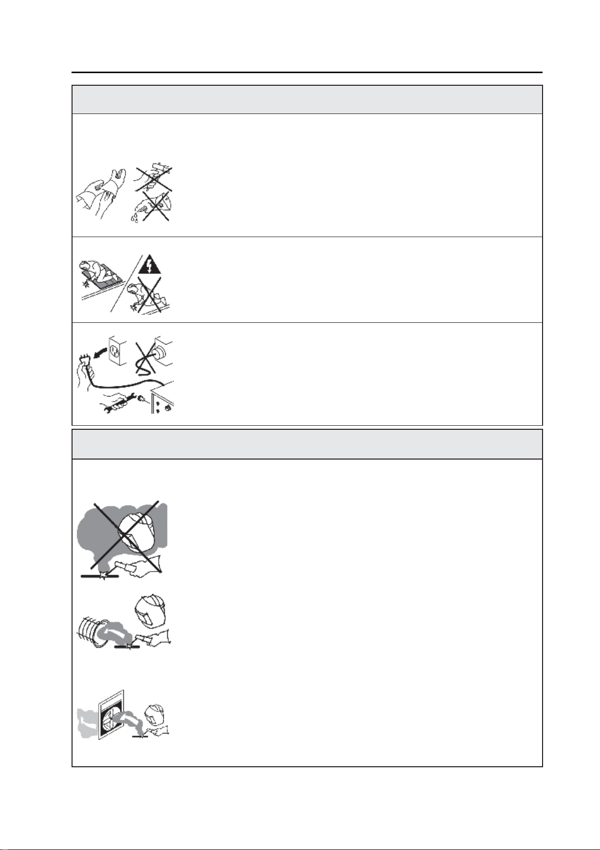
●Weardry,hole-freeinsulatingglovesandbodyprotection.
●
Do
not
touch
electrode
with
bare
hand.
Do
not
wear
wet
or
damaged
gloves
and
bodyprotection.
●Donottouchliveelectricalparts.
●Nevertouchelectrodewhileincontactwithworkingsurface,groundoranother
electrodewhichisconnectedtoadifferentmachine.
●Protectyourselffromelectricshockbyinsulatingyourselffromworkandground.
Usenon-flammable,dryinsulatingmaterialifpossible,orusedryrubbermats,dry
wood
or
plywood,
or
other
dry
insulating
material
big
enough
to
cover
your
full
area
of
contact
with
the
work
or
ground,
and
watch
for
fire.
●Neverconnectupmorethan1electrodesorwirestothemachine.
●Turnoffthemachine,whennotinuse.
●Disconnectinputplugorpowerbeforeworkingonmachine.
●
Frequently
inspect
input
power
cord
for
damage
or
bare
wiring
-
repair
or
replace
cord
immediately
if
damaged.
●
Be
sure
input
ground
wire
is
properly
connected
to
a
ground
terminal
in
disconnect
boxorreceptacle.
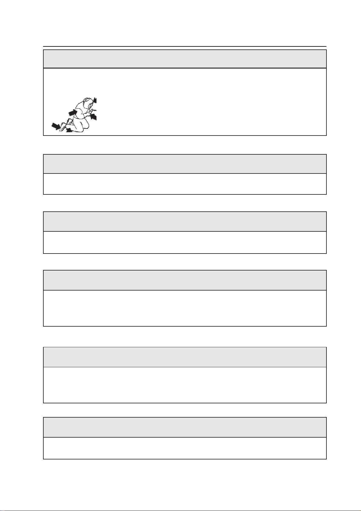
BREATHINGWELDINGFUMESCANBEHAZARDOUSTOYOURHEALTH
Inhalingfumesandgasesoveralongperiodoftime,generatedduringweldingisdangerousand
forbidden.
●Irritationoftheeyes,noseandthroataresymptomsofinadequateventilation.Take
immediatestepstoimproveventilation.Donotcontinueweldingif symptoms
persist.
●Installanaturalorforcedairventilationsystemintheworkarea.
●Installanadequateventilationsystemintheweldingandweldingarea,ifneeded
installasystemthatcanremovethefumeandvaporaccumulatedintheentirework
area,topreventpollutionuseadequatefiltrationindischarge.
●Intheeventofweldingandcuttinginsmall,confinedplaces,orweldinglead,
beryllium,cadmium,zinc,zinccoatedorpaintedmaterials;alsowearafreshair
suppliedrespiratorinadditiontotheabovementionedrules.
●Alwayshaveatrainedwatch-personnearby,whileworkinginsmallconfinedplaces.
Avoid
working
in
such
confined
places
if
possible.
●Ifgascylindersaregroupedinadifferentarea,makesurethatitisawell-ventilated
area.Whennotbeingused,turnoffthecylindervalve.
●Shieldinggassessuchasargonisdenserthanairandwhenbeingusedinconfined
places,canbeinhaledinplaceofair,andthisisdangerousforyourhealth.
●
Do
not
perform
welding
operations
near
chlorinated
hydrocarbon
vapors
produced
by
degreasing
or
painting.
-2-
SAFETY
RULES
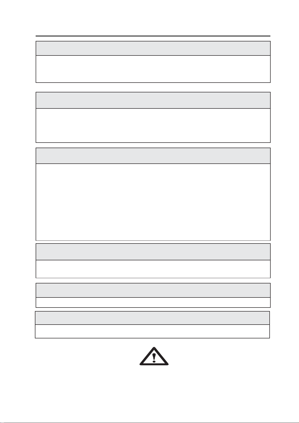
ARCRAYSCANBURNEYESANDSKIN
●Useadequateweldinghelmetwithcorrectshadeoffilter(4or13consideringTSEN
379)
to
protect
your
eyes
and
face.
●
Protect
open
parts
of
your
body
(arms,
neck
and
ears)
from
arc
rays
by
adequate
protective
clothing.
●
To
protect
others
by
arc
rays
and
hot
metals,
surround
the
working
area
with
flame
proof
curtains
which
are
higher
than
eye
level
and
put
up
warning
boards.
FLYINGMETALSCANINJUREEYES
●Weldingandcuttingcausesparksandflyingmetal.
●Topreventinjurieswearappropriatesafetyglasseswithsideshieldsevenunderyourweldinghelmet.
NOISECANDAMAGEHEARING
●Noisefromcertainindustrialprocessesorequipmentcandamagehearing.
●
Wear
approved
ear
protection
if
noise
level
is
high.
HOTPARTSCANCAUSESEVEREBURNS
●Donottouchhotparts.
●Allowcoolingtimebeforeservicing.
●
If
needed
to
hold
hot
parts,
use
appropriate
tool,
insulating
gloves
and
fireproof
clothes.
MOVINGPARTSCANCAUSEINJURY
●Keepawayfrommovingparts.
●Keepalldoors,panels,andguardsclosedandsecured.
●
Wear
shoes
with
metal
protection
over
the
fingers.
WORKINGINSMALLANDCONFINEDPLACESCANBEDANGEROUS
●Whileweldingandcuttinginsmall,confinedplaces,alwayshaveatrainedwatch-personnearby.
●Avoidworkinginsuchconfinedplaces.
-3-

SAFETY
RULES
WELDINGWIREMAYCAUSEINJURY
●
Do
not
point
the
gun
toward
any
part
of
a
human
body,
other
persons
or
any
type
of
metal
when
unwinding
welding
wire.
●
While
extracting
the
wire
from
the
spool
by
hand,
it
may
spring
suddenly
and
injure
you
or
a
nearby
person,
protect
especially
your
eyes
and
face.
●
Make
sure
that
there
is
no
one
close.
WELDINGCANCAUSEFIREOREXPLOSION
●Neverweldnearflammablematerial.Itmaycausefireorexplosions.
●Beforestartingtoweldorcut,moveflammablesawayorprotectthemwith
flame-proofcovers.
●Donotweldorcutonandcutclosedtubesorpipes.
●
Before
welding
and
cutting
on
closed
containers,
open
and
clear
them
entirely.
Weldingoperationsonthesepartsmustbeperformedwiththeutmostcaution.
●Neverweldorcutcontainersorpipescontainingorwhichhavecontained
substances
that
could
give
rise
to
explosions.
Welding andcutting equipmentwarmsupsoneverpositionthemonflammable
surfaces.
●
Welding
and
cutting
sparks
can
cause
fire.
For
that
reason,
keep
extinguishing
means,suchasfireextinguishers,waterandsandeasyreach.
●Haveandmaintainsecurityvalves,regulatorsandothervalvesontheflammable,
explosiveandcompressedgascircuitsingoodconditionbyperiodicalcontrols,
usedforweldingandcuttingoperations.
FALLINGUNITCANCAUSEINJURY
Wrong
positioned
power
source
or
other
equipment
may
cause
serious
injury
to
persons
or
damage
to
objects.
●Whilere-positioningthepowersourcealwayscarrybyusingtheliftingeye.Neverpullcable,hoseorGun.
Always
carry
the
gas
cylinders
separately.
●
Before
carrying
the
welding
and
cutting
equipment,
disassemble
all
the
connections
between
and
separately
carry
the
small
ones
by
hand
-
grips
and
the
big
ones
by
lifting
eyes
or
by
using
appropriate
vehicles
like
forklifts.
●
I
nstall
your
machine
on
flat
platforms
having
maximum
10
°
slope
that
it
does
not
fall
over.
Install
it
on
well
ventilated,
non-confined
places
away
from
the
dust,
also
avoiding
the
risk
of
falling
caused
by
cables
and
hoses.
For
gas
cylinders
not
to
fall
over,
attach
it
to
the
mobile
machine
or
to
the
wall
with
a
chain.
●Ensurethatoperatorseasilyreachthecontrolsandconnectionsonthemachine.
-4-
SAFETY
RULES
MAINTENANCEMADEBYUNQUALIFIEDPERSONSMAYCAUSEINJURIES
●
Electrical
devices
should
not
be
repaired
by
unqualified
persons.
Improper
repairs
can
cause
serious
injuries
or
even
death
during
applications.
●
The
components
of
the
gas
circuit
works
under
pressure.
The
service
given
by
unqualified
persons
may
cause
explosions
and
operators
can
be
injured
seriously.
OVERUSECANCAUSEOVERHEATING
●Allowcoolingperiod;followrateddutycycle.
●Reducecurrentorreducedutycyclebeforestartingtoweldagain.
●Donotblockairflowtounit.
●
Do
not
filter
airflow
to
unit
without
the
approval
of
manufacturer.
ARCWELDINGCANCAUSEINTERFERENCE
●
Electromagnetic
energy
arising
during
welding
and
cutting
operations
can
interfere
with
sensitive
electronic
equipment
such
as
microprocessors,
computers,
and
computer-driven
equipment
such
as
robots.
●Besureallequipmentintheweldingareaiselectromagneticallycompatible.
●
To
reduce
possible
interference,
keep
weld
cables
as
short
as
possible,
close
together,
and
down
low,
such
as
on
the
floor.
●
To
avoid
possible
EMC
damages,
locate
welding
operation
as
far
as
possible
(100
meters)
from
any
sensitive
electronic
equipment.
●Besurethisweldingmachineisinstalledandgroundedaccordingtothismanual.
●
If
interference
still
occurs,
the
user
must
take
extra
measures
such
as
moving
the
welding
and
cutting
machine,
using
shielded
cables,
using
line
filters,
or
shielding
the
work
area
.
STATIC(ESD)CANDAMAGEPCBOARDS
●Putongroundedwriststrapbeforehandlingboardsorparts.
●Useproperstatic-proofbagsandboxestostore,move,orshipPCboards.
PROTECTION
●
Do
not
expose
the
welding
machine
to
rain,
protect
from
water
drops
and
vapour.
●
The
lifetime
determined
by
Ministry
of
Industry
and
Trade
is
10
years.
OBEYALLTHESAFETYRULESSTATEDINTHEMANUAL!
-5-
LIFETIME

ELECTROMAGNETIC
COMPATIBILITY
EMC
)
ELECTROMAGNETICEMISSION
●
All
electrical
equipment
generates
small
amounts
of
electromagnetic
emission
due
to
current
transferring
in
the
equipment.
Electrical
emission
may
be
transmitted
through
power
lines
or
radiated
through
space,
similar
to
a
radio
transmitter.
When
emissions
are
received
by
other
equipment,
electrical
interference
may
result
.
Electrical
emissions
may
affect
not
only
welding
machines
but
also
many
kinds
of
electrical
equipment
like
radio
and
TV
reception,
numerical
controlled
machines,
telephone
systems,
computers
etc.
●
Welding
and
cutting
machines
have
been
designed
to
work
for
professional
and
industrial
use;
for
other
applications
to
contact
the
manufacturers.
●
The
user
is
responsible
for
installing
and
using
the
equipment
according
to
the
manufacturer
’
s
instructions.
If
electromagnetic
disturbances
are
detected
then
it
shall
be
the
responsibility
of
the
user
of
the
equipment
to
resolve
the
situation
with
the
technical
assistance
of
the
manufacturer.
In
some
cases
this
remedial
action
may
be
as
simple
as
earthing
the
welding
the
welding
circuit,
in
other
cases
it
could
involve
constructing
an
electromagnetic
screen
enclosing
the
power
source
and
the
work
complete
with
associated
input
filters.
In
all
cases
electromagnetic
disturbances
must
be
reduced
to
the
point
where
they
are
no
longer
troublesome.
●
The
circuit
may
or
may
not
be
earthed
for
safety
reasons.
Changing
the
earthing
arrangements
should
only
be
authorized
by
a
person
who
is
competent
to
assess
whether
the
changes
will
increase
the
risk
of
injury,
e.g.
by
allowing
parallel
welding
current
return
paths
which
may
damage
the
earth
circuits
of
other
equipment.
●Extraprecautionmayberequiredwhentheweldingpowersourceisusedinadomesticestablishment.
●SpecialmeasuresshallbetakentoachievecompliancewithweldingpowersourceincludingHFfrequencyfor
arcignitionandstabilizing;itmayberequireduseofshieldedcablesandinanycasetoresolvetheparticular
implementation(e.g.withrobot,computerandanyotherelectricalandelectronicequipmentconnectedto
weldingpowersource)tocallthetechnicalassistanceofthemanufacturer.
●EMCisClassAaccordingtoCISPRII.
ASSESMENTOFTHESURROUNDINGAREA
Beforeinstallingtheweldingandcuttingequipment,theusershallmakeanassessmentofpotential
electromagneticproblemsinthesurroundingarea.Thefollowingshallbetakenintoaccount-ifneeded
arrangetheworkinghoursthatnotcoincidewiththose.
●
Other
supply
cables,
control
cables,
signaling
and
telephone
cables;
above,
below
and
adjacent
to
the
welding
and
cutting
equipment,
●Radioandtelevisiontransmittersandreceivers,
●Computerandothercontrolequipment,
●Safetycriticalequipment,
●Presenceofheartbeatregulators,heartcells,hearingdevicesoretc.nearby,
●Equipmentusedforcalibrationormeasurement,
●
The
immunity
of
other
equipment
in
the
environment.
Theusershallensurethatotherequipmentbeingusedintheenvironmentiscompatible.Thismay
requireadditionalprotectionmeasures.
METHODSOFREDUCINGEMISSIONS
●Cuttingequipmentshouldbeconnectedtothemainssupplyaccordingtothemanufacturer’srecommendations.
Ourweldingmachinesarefilteredagainstemissionaccordingtostandards.Ifinterferencestilloccurs,itmay
benecessarytotakeadditionalprecautionssuchasfilteringofthemainssupply.
●
The
equipment
should
be
routinely
maintained
according
to
the
manufacturer
’
s
recommendations.
The
welding
and
cutting
equipment
should
not
be
modified
without
the
approval
of
manufacturer.
●
The
welding
and
cutting
cables
should
be
kept
as
short
as
possible
and
should
be
positioned
close
together,
running
at
or
close
to
the
floor
level.
Power
cables
and
signal
cables
should
be
kept
separately.
●Keepingcablesintheshapeof-8-andtapingtogetherreduceemission.
●
Connect
earth
clamp
to
work
-
piece
as
close
to
the
weld
as
possible.
But
the
user
should
be
control
whether
this
situation
damage
to
people
and
equipment
or
not.
-6-

TECHNICAL
INFORM
A
TION
1.TECHNICALINFORMATIONS
1.1GENERALEXPLANATIONS
●Thiscuttingmachineismanufacturedwithadvancedinvertertechnology.Withhigh-powercomponentIGBTand
byadoptingPWMtechnology.TheinverterconverttheDCvoltage,whichisrectifiedfrominputACvoltage,to
high20KHzfrequencyACvoltage.Asaconsequence,thevoltageistransformedandrectified.Therefore,itresults
themuchmoresmall-sizedofthepowersourceandlighterinweightoftheinvertercuttingmachine,whichratesthe
performanceofcuttingby30%.Thehighfrequencyoscillation,whichenablestheoutputofthehighfrequencyDC,
isemployedinthearc-startingsystem.Thefeaturesofthisproductareasfollowing:stablethecuttingcurrent
output,reliable,completelyportable,efficientandlownoisegeneratedwhilecuttingisperformed.
●CuttingProcessisavailablefor LGK-80S.
●Duringtheperformanceofcutting,thiscuttingequipmentisfeaturedwiththestabilityofcurrentoutputandthat
thecuttingcurrentoutputdoesnotvarywithvariationofthelengthofarc.
●Guaranteeofmaintenanceformainengineisoneyear,excludingotherspareparts.
●Duringtheguaranteemaintenanceperiod,allmaintenanceisfreeofcharge,excludingthedeliberateddamageto
thiscuttingequipment.
●Onlyqualifiedtechnicianareauthorizedtocarryouttherepairstaskofthiscuttingmachineincaseofmachine
fault.
●THEMAINTECHNICALSPECIFICATIONSorDATAPLATEonthecuttingmachine.
1.2APPLICATIONAREA
1.3SYMBOLANDMEANINGONDATAPLATE
threephaseinputACpower supply,RectifierDCcurrentor voltage output
Output Characteristicsofthecuttingpowersourceisconstantcurrent(CC)outputfor LGK-80S.
Norm:Applicationstandards,forexample,EN60974-1orIEC60974-1.
-7-
●LGK-80S cuttingmachinesare threephase,
380V,50Hz,constantcurrent(CC)outputpower
sourcesespeciallydesignedfortheairplasmaarc
cutting.
●Allthecontrolsandadjustmentknobofthecutting
powersourceareplacedontothefrontpanelforeasy
operation.
●CuttingCable,the torch, EarthCableand gas
hose canbe easyconnectedto thepowersource.
●Outputcurrentofthe LGK-80S cuttingmachine
canbeadjustedbyacuttingcurrentadjustment
knob.
●LGK-80S isverygoodselectionformedium
thicknessmetals(upto20mm)cutting.It isalsoa
verygoodchoiceforstainlesssteelandmetalscutting.
Thismachineshouldbeselectedforhighdutycycle
cuttingapplications.

TECHNICAL
INFORM
A
TION
U1:RatedACinputvoltageofthecuttingpowersource,3~,380V,etc.
I1max:Max.inputcurrent.
I1eff:Max.effectiveinputcurrent.
50HZ:RatedfrequencyofsinglephaseACpowersupply.
X: Rated dutycycle.Itistheratiobetweentheloaddurationtimeandthefullcycletime.
Note1: Thisratioisbetween0~100%.
Note2: Forthisstandard,onefullcycletimeis10min.Forexample,iftherateis60%,theloadedtimeshallbe6
minutesandresttimeshallbe4minutes.
Dutycycleisbasedonatenminuteperiod.Thismeansthatthearcmaybedrawnfortwominutesoutof
eachtenminuteperiodwithoutanydangerofoverheating.Ifitisusedmorethantwominutesduringseveral
successivetenminutesperiods,itmayoverheat.
U0:No-loadvoltage
Itistheopen-circuitoutput voltageofthecuttingpowersource.
I2:outputcurrentorcuttingcurrent
U2:Outputloadvoltageorcuttingvoltage. Theratedloadedoutputvoltage U2=80+0.04I2forPlasmaCutting.
A/V A/V:Theadjustablerangeofcurrentanditscorrespondingloadvoltage.
S1:TheratedInputPower,KVA
IP:Protectiongrade.Forexample,IP21S,approvingthecuttingmachineassuitableforuseindoors;IP23S,.
approvingthecuttingmachineassuitableforuseoutdoorsintherain.
Suitableforhazardousenvironments.
Class:H Insulationgrade.
1.4Environmentalconditions
Thepowersourceshallbecapableofdeliveringtheirratedoutputwhenthefollowingenvironmental
conditionsprevail:
e)baseoftheweldingpowersourceinclinedupto10°
-
8
-
S

INS
T
ALL
A
TION
2.INSTALLATION
2.1UPONRECEIPTANDCLAIMS
2.2WORKAREA
2.3INSTALLATIONANDUSAGEOFTHEMACHINE
Onlyqualifiedpersonsshouldinstall,useorservicethisequipment.Protectyourselfandothers
frompossibleseriousinjuryordeath.
WARNING: Donotoperatewithcoversremoved.Disconnectinputpowerbeforeservicing.
Donottouchelectricallyliveparts.
●Beforestartingtheinstallation,checkwiththepowercompanytobesureyourpowersupplyisadequate
forthevoltage,amperes,phase,andfrequencyspecifiedonthecuttingmachinenameplate,Alsobesurethe
-
9
-
●Besurethatyouhavereceivedalltheitemsthatyou
haveordered.Incaseofanyitemsaremissingordamaged,
contactyoursupplierimmediately.
●Besurethatnoneofthefollowing4items are
missing
in
the
box.
Power Source
EarthClampandCable
CuttingTorch
UserManual
●Make sure that your line voltage is
threePhase,380V,50Hz andyouhaveaneutraland
earthlinepresentatyourworkplace.
●Inordertocooldownthemachineandhave
anefficientwork,keepthemachineatleast30
cmawayfromthesurroundingobjects.Donot
placeanyheatsource,asoven,tofrontsideof
themachinewherethecoolingair istakenfrom.
●Donotplacethemachineinsmalland narrow
places.Bewareofexcessivedustanddirt.
●Keepyourmachineawayfromwetand humid
places.
●Donotoperatethemachineunderdirectsunlight,rain
andwind.Machinesshouldbeoperatedon lower
capacities whenambientairtemperatureexceeds40ºC.
●Pleaseuseasuitableexhaustsystemforgases
andcuttingvapour.Usebreathingapparatusifthereisa
riskofinhalinganyweldingorcuttingvapour.
●Avoidcuttingwhereair-flowishigh.Protect
thecuttingareawithcurtainsormobilescreens.
●Transportandplacethedeviceonfirmand
levelgroundsothatitmaynotfallover.The
maximumpermissibleangleofinclination
fortransportandassemblyis10°.
●Thismachineisprotectedelectronically
againstoverloading.Donotusestrongerfuses
thanthosestatedonthetypeplateofthe
device.
●Ensurethattheearthclamphasgoodand
directcontactnearthecuttinglocation.Do
notdirectcuttingcurrentoverchains,ball
bearings,steelcables,protectionconductors
etc.,Otherwisetheymaymelt.
●Ensurethatoperatorscaneasilyreachthe
machine
controls
and
equipment
connections.
●Useliftingeyesforliftingthemachine.
Donotliftthemachinebyusingafork-liftora
similar vehicle.

INS
T
ALL
A
TION
plannedinstallationwillmeetalllocalandnationalcoderequirements.Somecuttingmachinesmaybe
operatedfromasinglephaselineorfromonephaseofatwoorthreephaseline.
●Beforeconnectingtheinputcabletothepowersupply,checkthatthepower(on-off)switchoperatesin
thepositioncorrespondingtotheinputvoltagethatthemachinewillbeconnectedto.
CAUTION:Ifthepowerswitchsettingdoesnotmatchtheinputpowervoltage,youmayburnupthe
cuttingmachine!
●Connectthe “PE”or green/yellowgroundingwire intheinputcordtoasystemgroundperthe
applicablenationalandlocalcodes.
2.3.1CONNECTTHEMACHINETOPOWERSUPPLY
●Theconnectiontothemainlinesismadebytheenduser.Ithastobeperformedbyqualifiedelectriciansorby
thepeopletrainedinthisarea.
●Power supply cable tothemachine mustbeconnectedto themain power supply switch.Themain power
supplyhasbeenlabeledinthe nameplateof themachine,forexample,3~,50Hz,380VAC.
●The4x2.5mm²power supply cable shouldbeused.
●Beforeturningonthemain power supply switch usermustcheckcarefullytheseconnections ofthepower
supply cable andearth cable (Yellow/Green) tothemachine.
Besurethatconnectionsarefastenedtightly.Looseorincorrectfasteningmaycause
theconnectiontooverheator burn.Unexpectedresultsmayoccurifamistakeismade
inthenetworkconnection.Payattentionthattheconnection of the “PE”or green/yellow
groundingwireoftheinputcordtoasystemground.
Figure1:The front panel ofthe cutting powersource
POWER Pilotlightof andLED1forthe power supply
O.H PilotlightofLED2forOverheating protection
CUTTINGCURRENT Cuttingcurrentadjustmentknob
LOWINPUT PilotlightofLED3forlow power supplyvoltageorlowvoltage protection.
SwitchofCUTTINGorCHECKAIR CUTTINGorCHECKAIRSelectionSwitch
-1
0
-
Adjustmentofthe
cuttingcurrent

INS
T
ALL
A
TION
2.3.2CONNECT OUTPUT(-)ANDOUTPUT(+)
●Connectthework-piece to Output(+), notLoose.
●ConnecttheCuttingtorchto Output( )or connectoroftheCuttingtorch, notLoose.
●Connecttheairtubetothecoppernozzleoftheback panel.Theairsupplysystemshouldbewellconnectedin
ordertokeepairoutput,whichisofcriticalimportanceforcuttingoperation.
●BesurethatconnectionsarecorrectandnotLoose.
●Turnon thepower supply ON/OFFswitch.
●SetCHECKAIR,CheckAir flow andpressure!
●SetCUTTING,thecuttingprocesswillbecarriedoutbyusingthe torch switch.
●Toincreasethequalityofcutting,earthclampontheworkpieceshouldbeclampedtightlyandasclosetothe
cuttingareaaspossible.
2.3.3CONNECTTOTHEREGULATORANDAIRSUPPLY
●ConnecttheairregulatortotheCuttingmachine.Connecttheairregulatortotheairsupply.
●Connectoneendoftheairregulatortotheairsupplyinletofthecuttingpowersource.Theotherendisfor
connectingthehosetotheairsupply.
●Screwtheairhosepressureregulatorandopen the airsupply.
●SettingoftheAirflowwiththeadjustment valveoftheregulator. Usually,thevalveisabout0.17m3/min.
3.USAGEINFORMATION
3.1THEPOWERSOURCEFRONTPANEL
●Onthefrontcontrolpanelofthecuttingpowersource,therearePilotlights,checkairandcuttingswitch,Cutting
currentcontroller,etc.
●A:Cuttingcurrent adjustmentknob orcontroller.
●LED1(POWER):PilotlightofthepowersupplyintheON/OFFpowersourceswitch.TheLED1islighted
whenthe switchisON.
●LED2(O.H):PilotlightofOver-heating,Overcurrentorvoltage.TheLED2islightedwiththermaloverload
protectionorovercurrent.LED2ison,incasethatthiscuttingequipmentisofoverheatingprotectionstatus.
Overheatingarisesifthiscuttingpowersourceisoverloaded.Thiscuttingequipmentautomaticallyrestarts
whenthetemperatureinsideofthiscuttingequipmenthasfallen,andpilotlampisoff.
●LED3(LOWINPUT):Pilotlightoflow power supplyvoltageorlowvoltage protection.TheLED3islighted
whenthe power supplyvoltage is low.
CAUTION:Incasethatthiscuttingequipmentisofovercurrentorvoltageprotectionstatus,LED2ison.At
thistime,Switchofthecuttingpowersourcemustbeturnoff,andthenSwitchshouldbeturnon,thecuttingpower
sourcewould beabletocut.
3.2ADJUSTINGTHEAIRFLOWFORTHECUTTINGPROCESS
●SettingoftheAirflowwiththeadjustment valve. Usually,thevalveisabove0.17m3/min.
3.3 Arcstartingforthecuttingprocess
Pressthetorchswitch.Thearcismadebetweentheworkandthecuttingtorch,andcuttingoperationis
accessible.
3.4ADJUSTINGTHECUTTINGCURRENT
Thecuttingcurrentisselectedaccordingtothethicknessoftheworkpiece.
-1
1
-

MAINTENANCEANDTROUBLESHOOTING
4.MAINTENANCEANDTROUBLESHOOTING
Onlyqualifiedpersonsshouldinstall,useorservicethisequipment.Protectyourselfandothers
frompossibleseriousinjuryordeath.
WARNING: Donotoperatewithcoversremoved.Disconnectinputpowerbeforeservicing.
Donottouchelectricallyliveparts.
WARNING: Beforeremovinganyscrewonthemachineformaintenance,powersupplymustbe
disconnectedfromtheelectriclinesandenoughtimeshouldbeallowedforcapacitordischarging.During
maintenance,payattentiontothemovingpartsinthemachine.
4.1PERIODICMAINTENANCE
Onceeverythreemonths
●Cleanthelabelsonthemachine.Repairorreplacethewornoutlabels.
●Repairorreplacethewornoutcuttingcables.
●Cleanandtightenweldterminals.
●CheckGun,earthclampandtheircables.
●Checkthemainconnectionsinsidethemachine.
Onceeverysixmonths
●Openthecoversofthemachineandcleanwithdryair.
NOTE: Theaboverecommendedmaintenanceperiodsareindicativeaccordingtoour
generalexperience,thesemayvaryfromworkshoptoworkshopandtheconditionsofthe
cuttingsite.
4.2NONPERIODICMAINTENANCE
●Thecuttingpowersource mustbecleanedwithdryair.
●
Nozzleonthetorchhavetobecleanedregularlyandchangedifrequired.Contacttips
mustbeingoodcondition,longertipsgenerallygivebetterresults.
Exposuretoextremelydusty,damp,orcorrosiveairisdamagingtothecuttingmachine.Inordertopreventany
possiblefailureorfaultofthiscuttingequipment,cleanthedustatregularintervalswithcleananddrycompressed
airofrequiredpressure.
Pleasenotethat:lackofmaintenancecanspelltotheunavailabilityandcancellationoftheguarantee;the
guaranteeofthiscuttingequipmentwillbenolongeravailableincasethatithasbeenattemptedtotakethe
machineapartoropenthefactory-madesealingofthemachine.
-
12
-

MAINTENANCE
AND
TROUBLESHOOTING
4.3BASICTROUBLESHOOTING
FaultSymptoms Rectification
1.Thecuttingequipment
isoperated,LED1lampis
off,nooutput,thebuilt-in
fanunavailable.
1.Possiblefunctionfailureofpowerswitch.Compensateitifnecessary.
2.Possibleunavailabilityofinput.Compensateitifnecessary.
3.Possibleshortcircuitofinputcable,Compensateitifnecessary.
2.Whilethisequipmentis
operated,LED1ison,no
output,thebuilt-infan
unavailable.
1.Possibleunavailabilityoftheconnectionofswitch.Reconnectit.
2.PCBispossiblydamaged.Replaceitifnecessary.
3.Whilethisequipmentis
operated,thebuilt-infan
functions,LED2isoff,no
HFelectricityreleasing,
arcstartingunavailable.
1.PCBispossiblydamaged.Replaceitifnecessary.
2.Possibleelectricityleakageofcapacitors,replacethemifnecessary.
3.Checktheconnectionwhetherisavailable.Iffaultcannotberectified,please
contactthesupplierforfurtheradvice.
4.Possibledamageofthecuttingtorch.Replaceitifnecessary.
4.LED2isoff,andcutting
currentoutputis
unavailable.
1.Possibledisconnectionofcuttingtorchcable.
2.Possibledisconnectionofearthcable,orunavailabilityofconnectionoftheearth
cableandworkpiece.
3.Theconnectionbetweenpositiveoutputterminalortheairorelectricityoutput
terminalandthiscuttingequipmentispossiblyunavailable.Reconnectthem.
5.Whileisthiscutting
equipmentisoperated,
LED2isoff,noelectricity
releasing,andthearc
startingavailable.
1.ThecableconnectionbetweenthetransformerofarcstartingandpowerPCBis
possiblyunavailable.Checkandreconnectit.
2.Possibleoxidizationofthesparkgappartsoccurs.Orthedistanceislargerthan
themaximumdistanceavailable.Removetheoxidizationofthesepartsandadjust
thedistanceofthesparkgappartsto1mm.
3.Possibledamagetoswitch.Replacethemifnecessary.
4.HFarcstartingcircuitarepossiblydamaged.Checkandreplacethemif
necessary.
6.Whilethiscutting
equipmentisoperated,
LED2ison,andthereis
nooutput.
1.Itispossibleofover-currentprotectionstatus.WaittilltheLED2isoff,andrestart
thiscuttingequipment.
2.PossiblefaultwithInvertercircuit.DisconnecttheplugofPCB.Andrestartthis
cuttingequipment.
3.PCBispossiblydefective.Replaceit.
4.PossibledamageoftransformerofcenterPCB.Replaceitifnecessary.
5.Iftheindicatorisoff,possibledamageofsecondaryrectifieroftransformer.
Replaceitifnecessary.
6.Possibledamageoffeedbackcircuit.Replaceitifnecessary.
7.Unstablecurrent is
unavailable.
1.Possibledamageofthecurrentcontroller.Replaceitifnecessary.
2.Theconnectionofthiscuttingequipmentisnotavailable.
-
13
-
Table of contents


