Introduction
Thank you for choosing TOPP PRO. The new TOPP PRO ARRAY SERIES cabinets have been
designed to provide a cost effective high grade solution while maintainig high quality cabinet
construction and optimum components.
The array series, can be used for all types of applications including, but not limited to, churches,
conference centers and discos.
The woofer and neodymium driver combination provides excellent performance rivaling those
cabinets costing much more.
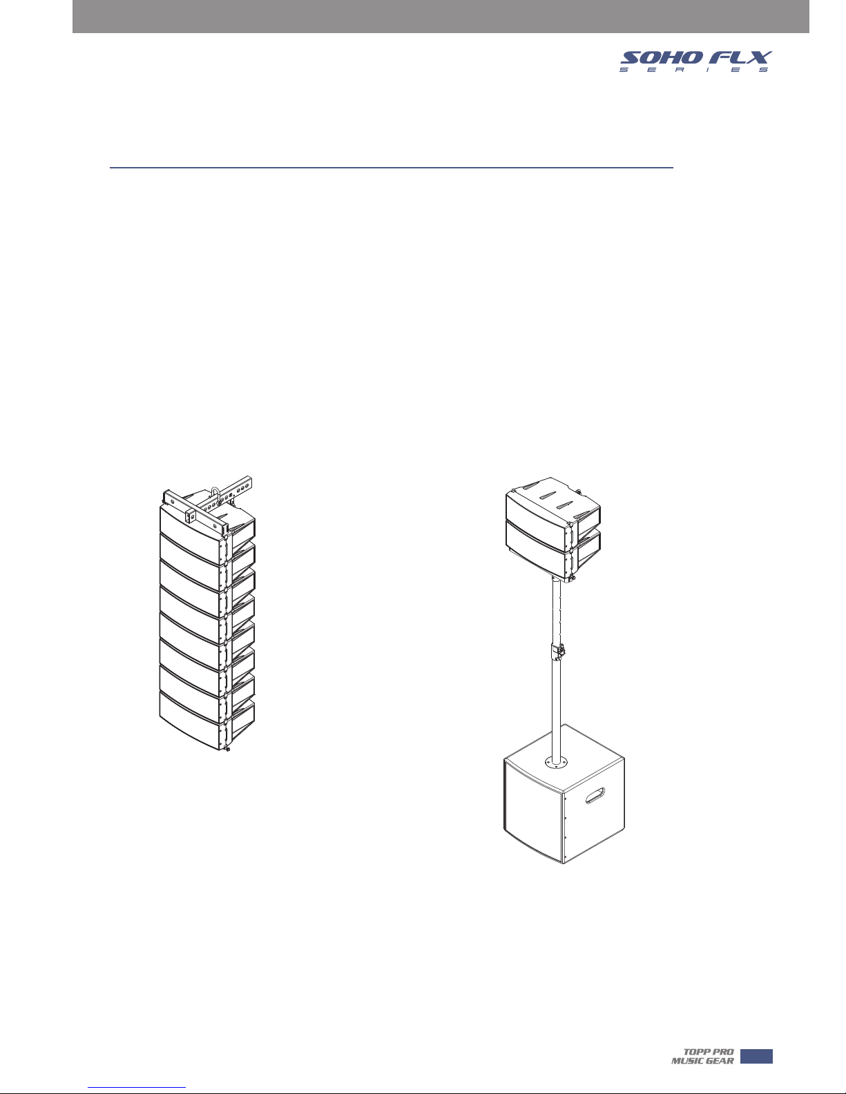
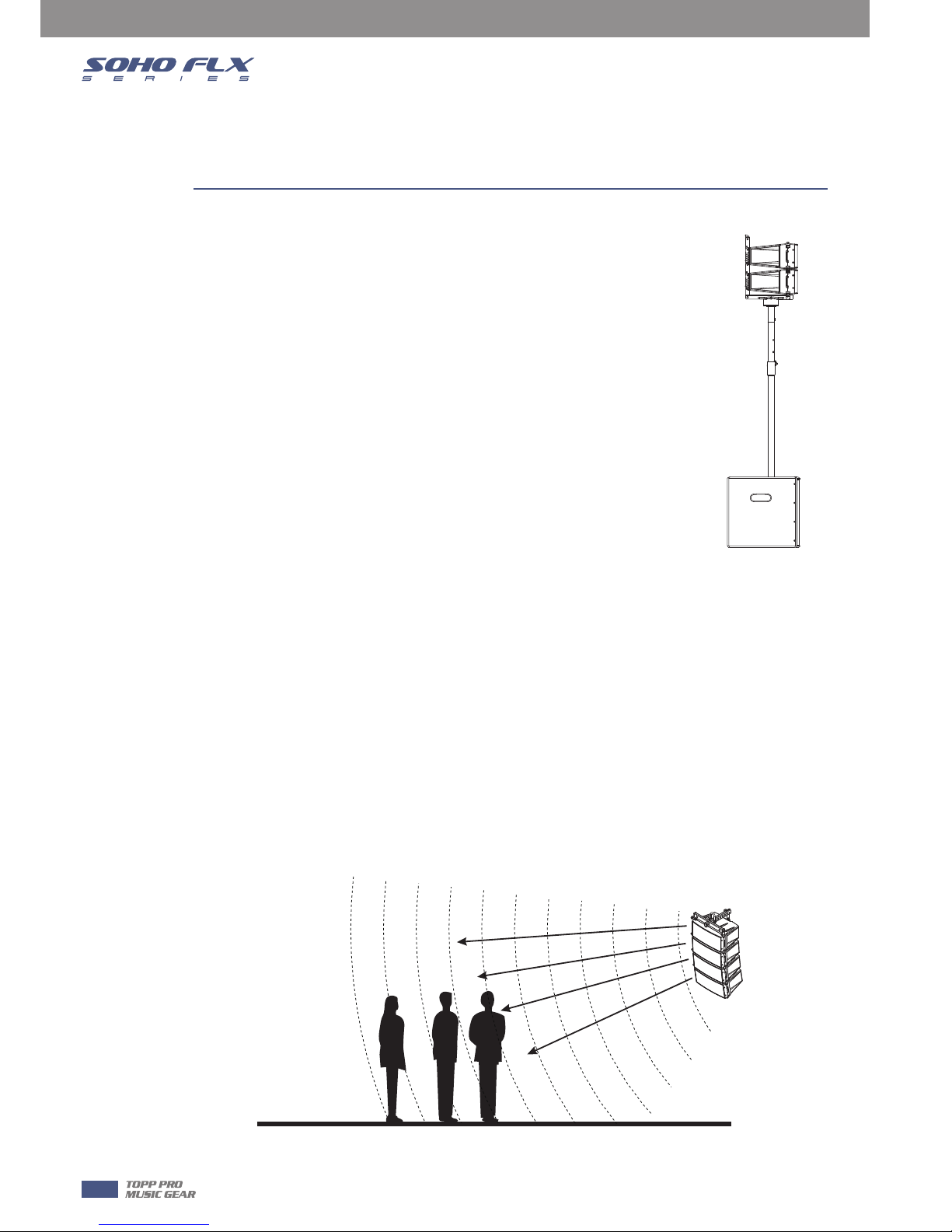
Speakers should be placed in a position that allows for unobstructed sound projection. In many
instances it is beneficial for speakers to elevate on tripod stands to achieve maximum dispersion
and reach. Consider TOPP PRO speaker stand or equivalent to raise speakers.
Using quality cables ensure best possible sound. Consider using TOPP PRO 16 or 14 gauge
cables or equivalent.
For best results match the speakers to a good amplifier that matches the wattage and
impedance of your speakers. Proper amplification power results in good quality audio and
longer component life. Check out.
Avoid pointing microphone directly at an amplified speaker otherwise could cause feedback
possible damaging speaker components and your hearing.
Our Professional Audio Products are designed and tested by a highly qualified engineering team
with more than 20 years of experience. Great care is placed in delivering products with excellent
performance, specifications and dependable reliability. Also great emphasis is placed in creating
and bringing to market products that can fill multiple applications and also offer customers
exceptional value.
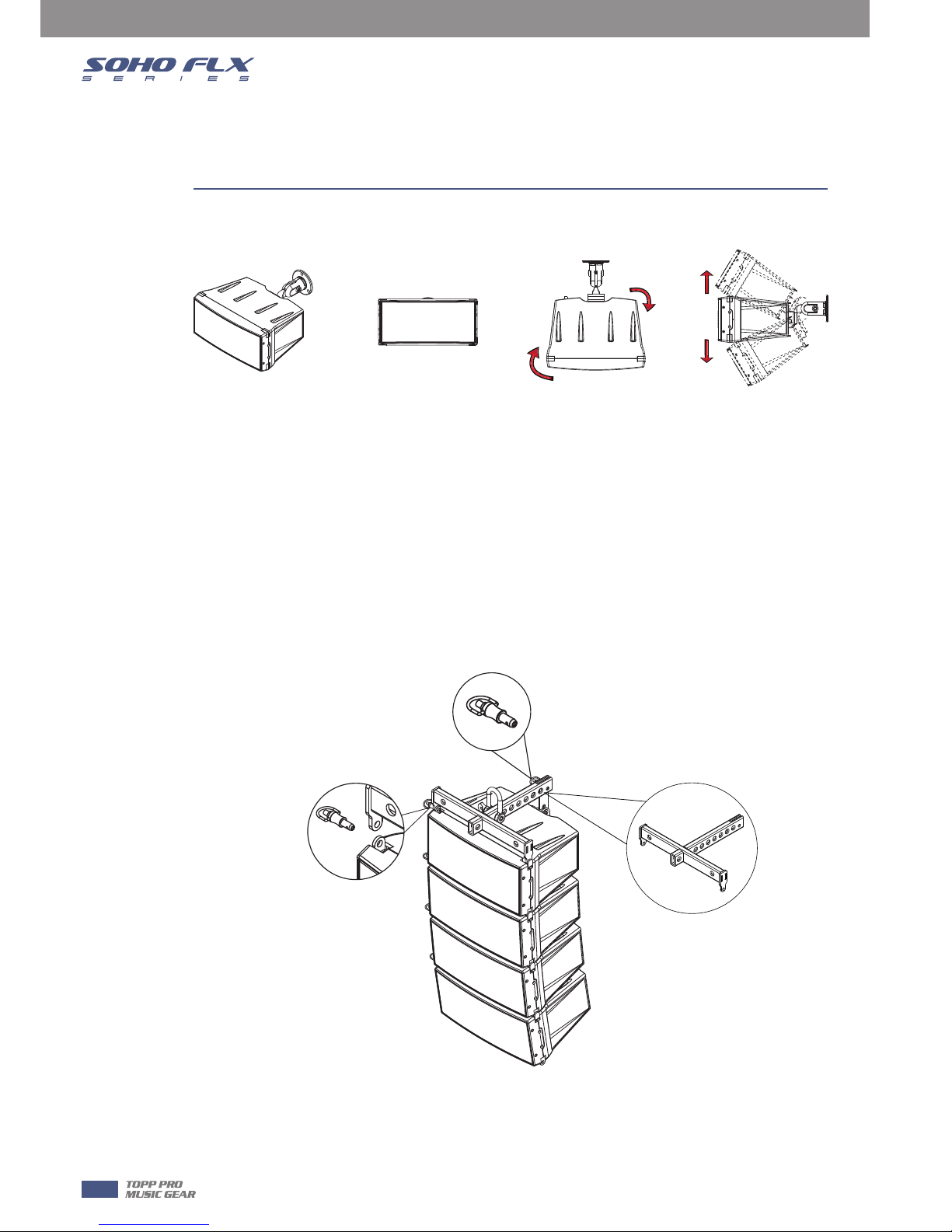
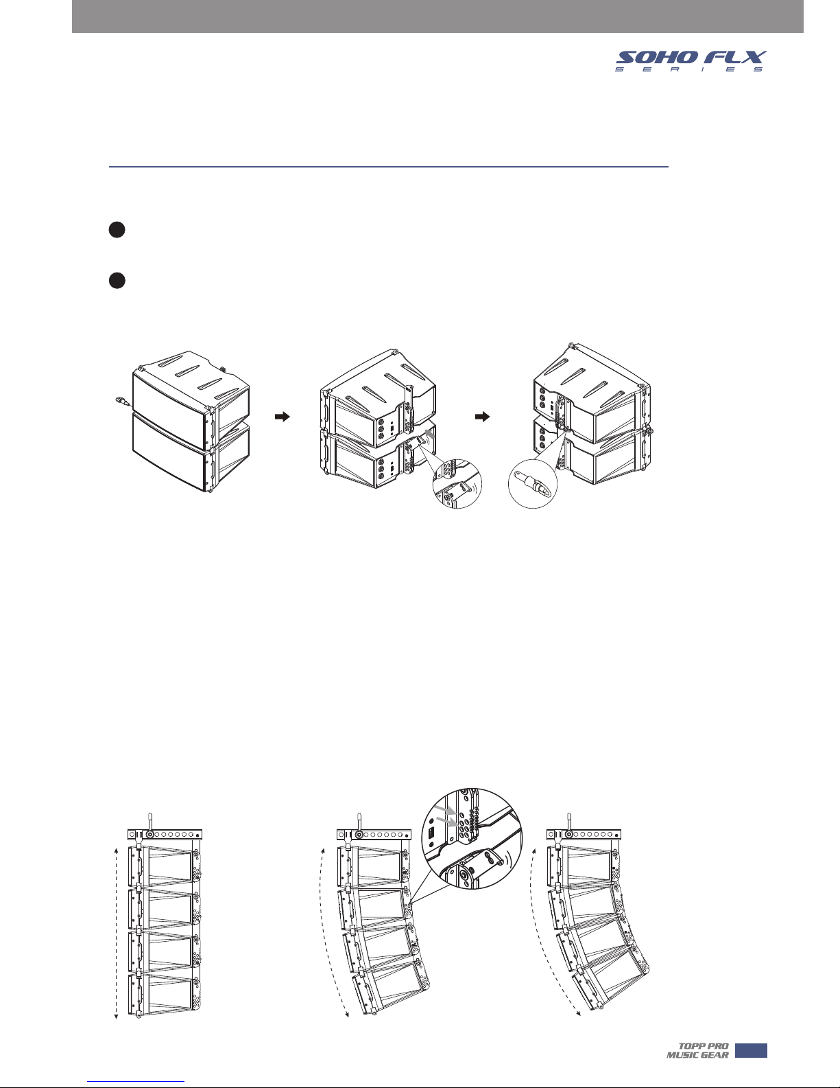
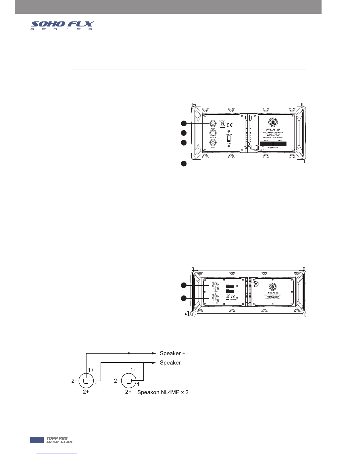
Installation Tips
Usefull Data
Please write your serial number here for future reference.
4