Torin BIG RED T51201 User manual

OWNER’S MANUAL
12 TON SHOP PRESS
Item: T51201
Questions, problems, missing parts? Before returning to your retailer, call our customer service department at
1-888-44-TORIN (1-888-448-6746), 8 a.m.- 5 p.m., PST, Monday-Friday.
Read carefully and understand all ASSEMBLY AND OPERATION INSTRUCTIONS before operating. Failure
to follow the safety rules and other basic safety precautions may result in serious personal injury.
Version 20180927

2
IMPORTANT
OWNER / USER RESPONSIBILITY
INTENDED USE
TECHNICAL SPECIFICATIONS
Before You Begin Register This Product.
For future reference, record the model name, model number, date of manufacture and purchase date of this
product. You can nd this information on the product.
Model Name ________________________
Model Number ________________________
Date of Manufacture _______________________
Date of Purchase ________________________
Description
Item T51201
Capacity 12 TON
Bed Opening 3-1/8 inch
Work Range 0~24 inch
Stroke Length 6-7/8 inch
Inside Bed Dimensions L x W 16-5/16 x 3-1/8 inch
Dimensions L x W x H 20-7/8 x 19-11/16 x 48-7/16 inch
DO NOT OPERATE OR REPAIR THIS PRODUCT WITHOUT READING THIS MANUAL.
Read and follow the safety instructions. Keep Instructions readily available for operators. Make certain all
operators are properly trained and understand how to safely and correctly operate the product. By proceeding
you agree that you fully understand and comprehend the full contents of this manual. Failure to operate this
product as intended may cause injury or death. The manufacturer is not responsible for any damages or injury
caused by improper use or neglect. Allow product operation only with all parts in place and operating safely.
Use only genuine replacement parts. Service and maintain the product only with authorized or approved
replacement parts; negligence will make the product unsafe for use and will void the warranty. Carefully
inspect the product on a regular basis and perform all maintenance as required. Store these instructions
in a protected dry location. Keep all decals on the product clean and visible. Do not modify and/or use for
any application other than that for which this product was designed. If you have any questions relative to a
particular application, DO NOT use the product until you have rst contacted the distributor or manufacturer to
determine if it can or should be performed on the product.
For technical questions please call 1-888-448-6746.
This equipment is designed for automotive, truck, implement, eet, and industrial repair shops where pressing,
bending, straightening and forming tasks are required. Typical applications include installation and removal of
alternator and power steering pump bearings, axle bearings, transmission bearings, seals, U-joints and many
other jobs.

3
GENERAL SAFETY RULES
GENERAL SAFETY RULES
IMPORTANT SAFETY CONSIDERATIONS
WARNING: Read and understand all instructions. Failure to follow all instructions listed below may result
in serious injury.
WARNING: The warnings, cautions, and instructions discussed in this instruction manual cannot
cover all possible conditions or situations that could occur. It must be understood by the operator
that common sense and caution are factors which cannot be built into this product, but must be supplied
by the operator.
CAUTION: Do not allow persons to operate or assemble this Shop Press until they have read this manual
and have developed a thorough understanding of how the Shop Press works.
SHOP PRESS USE AND CARE
INSPECTION
• Do not modify the Shop Press in any way. Unauthorized modication may impair the function and/or
safety and could affect the life of the equipment. There are specic applications for which the Shop Press
was designed.
• Always check of damaged or worn out parts before using the Shop Press. Broken parts will affect the
Shop Press operation. Replace or repair damaged or worn parts immediately.
• Store idle Shop Press. When Shop Press is not in use, store it in a secure place out of the reach of
children. Inspect it for good working condition prior to storage and before re-use.
• Not for use by children or people with reduced mental capacity.
• Do not use under the inuence of drugs or alcohol.
• Ensure children and other bystanders are kept at a safe distance when using shop press.
• Inspect the shop press carefully before each use. Ensure the shop press is not damaged, excessively worn,
or missing parts.
• Do not use the shop press unless it is properly lubricated.
• Using a shop press that is not in good clean working condition or properly lubricated may cause serious
injury.
• Inspect the work area before each use. Make sure it is free and clear of any potential hazards.

4
SAFETY MARKINGS
WARNING!
1. Study, understand, and follow all instructions before operating the device.
2. Do not exceed rated capacity.
3. Prior to use, make sure the press is securely anchored.
4. The press shall be installed and operated in accordance with federal (OSHA), state, and local safety
standards.
5. Ensure the work area is clean and free of any hazards before operation.
6. Operators and observers shall wear eye protection that meets ANSI Z87.1 and OSHA standards.
7. Keep hands, arms, feet, and legs out of the work area. Accidental slippage can result in personal injury.
8. Use appropriate guarding to contain any pieces that may break or y apart when applying force.
9. Use only press accessories having a capacity rating equal to or greater than the capacity of the press.
10. Verify lift cables are slack before pressing on the bolster.
11. Avoid off-center loads.
12. No alterations shall be made to the product.
13. Do not use this press for any use other than the manufacturer specied usage.
14. Failure to heed and understand these instructions and markings may result in personal injury, property
damage, or both.
DO NOT OPERATE OR REPAIR THIS EQUIPMENT WITHOUR READING THIS MANUAL.
To maintain the Shop Press and user safety, the responsibility of the owner is to read and follow these
instructions. Inspect the service shop press for proper operation and function. Keep instructions readily
available for equipment operators. Make certain all equipment operators are properly trained; understand
how to safely and correctly operate the unit. Allow unit operation only with all parts in place and operating
properly. Use only genuine replacement parts. Service and maintain the unit only with authorized or approved
replacement parts negligence will make the shop press unsafe for use and void the warranty. Carefully inspect
the unit on a regular basis and perform all maintenance as required. Store these instructions in the handle of
your shop press. Keep all decals on the unit clean and visible.
Safety: always follow safety precautions when installing and operating this shop press. Keep all decals on
the unit clean and visible. Before proceeding that you fully understand and comprehend the full contents of
this manual. Failure to operate this equipment as directed may cause injury or death. The distributor is not
responsible for any damages or injury caused by improper use or neglect.

5
GENERAL SAFETY INSTRUCTIONS
PLEASE READ THESE INSTRUCTIONS CAREFULLY. NOTE THE SAFETY INSTRUCTIONS AND
WARNINGS. USE THE PRODUCT CORRECTLY AND WITH CARE FOR THE PURPOSE OF WHICH IT IS
INTENDED. FAILURE TO DO SO MAY CAUSE DAMAGE TO PROPERTY AND/OR SERIOUS PERSONAL
INJURY. PLEASE KEEP THIS INSTRUCTION MANUAL SAFE FOR FUTURE USE.
We’ve done all we can to assure this press offers the outmost in safety, but you have to do your part. No
amount of warning can take the place of your good judgment, so make sure it’s the rst thing you bring to any
job. Beyond that here are some obvious tips:
• Steel and other materials can shatter, so always use protective eyewear that complies with the appropriate
ANSI code.
• If you detect anything that may indicate imminent structural failure, stop using the press immediately and
inspect it thoroughly.
• Bolt the press to the oor if it is to be used on bulky or unstable items.
• Do not use press to compress springs or any other item that could disengage and cause a potential ying
hazard.
• Use this press for the purpose for which it is intended. Do not use it for any other purpose it is not designed
to perform.
• Keep children and unauthorized persons away from the work area.
• Contain loose tting clothing. Remove ties, watches, rings and other loose jewelry and contain long hair.
• Wear ANSI approved impact safety goggles, full-face impact safety shield and heavy-duty work gloves
when operating the press.
• Keep proper balance and footing, do not overreach and wear nonskid footwear.
• Only use this press on a surface that is stable, level, dry and not slippery, and capable of sustaining
the load. Keep the surface clean, tidy and free form unrelated materials and ensure that there is adequate
lighting.
• Inspect the press before each use. Do not use if bent, broke, cracked, leaking or otherwise damaged. Do
not use if any suspect parts are noted or if the shop press has been subjected to a shock load.
• Check to ensure that all applicable bolts and nuts are rmly tightened.
• Ensure that work piece is center-loaded and secure.
• Keep hands and feet away from bed area at all times.
• Do not use the shop press to compress spring or any other item that could disengage and cause a potential
hazard. Never stand directly in front of loaded press and never leave loaded press unattended.
• Do not operate the press when you are tired or under the inuence of alcohol, drugs or an intoxicating
medication.
• Do not allow untrained persons to operate the press.
• Do not make any modications to the press.
• Do not use brake uid or any other improper uid and avoid mixing different types of oil when adding
hydraulic oil. Only good quality hydraulic jack oil can be used.
• Do not expose the press to rain or any other kind of bad weather.
• If the press needs repairing and/or there are any parts that need to be replaced, have it repaired by
authorized technicians and only use the replacement parts supplied by the manufacturer.

6
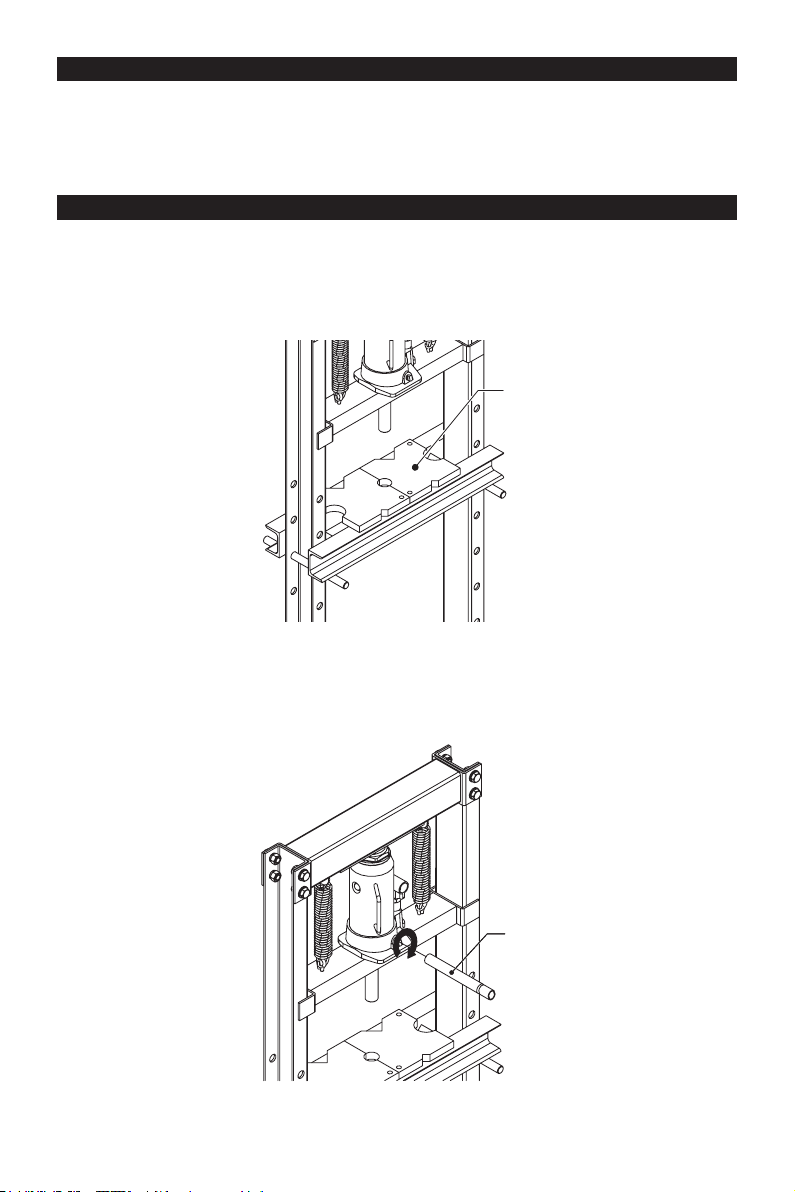
ASSEMBLY
All numbers in parenthesis () refer to the index number from the parts breakdown
1. Attached rail sections (16) to left and right posts
and lower cross member (24) using bolts (15),
washers (17), lock washers (18) and nuts (19).
3. Put the frame in an upright position, and attach
the upper crossbeam (2) and attached the springs
(6). Then attach eye hooks (8), using nuts (10) to
middle bolster (19). The attach springs to middle
bolster. (Middle Bolster will then suspend between
left and right frame posts.)
4. Carefully place 12 ton hydraulic bottle jack (7)
in between the middle bolster (9) and upper
crossbeam (2). Adjust the nuts (10) to the proper
position once jack has been installed.
2. Put the press frame in an upright position, attach
upper crossbeam (2) to left and right posts (14)
using bolts (1), washer (2), lock washer (3) and
nuts (4). Hook mounts should face down on upper
crossbeam.
19
16
17
15
24
18
14
2
4
14
3
2
1
10
9
8
2
6
9
2
7

7
5. Insert lower bolster pins (13) into the holes in the
posts. Then insert the lower bolster (11) into press
frame and onto lower bolster pins.
6. Check that all fasteners are tightened and insert
the handle into the handle socket.
7. Place the bolster plates (12) on lower bolster (11).
8. Assembly is now complete.
13
11
12

8
IMPORTANT: BEFORE FIRST USE
All numbers in parenthesis () refer to the index number from the parts breakdown. Perform the following Air
Purge Procedure to remove any air that may have been introduced into the hydraulic system as a result of
product shipment and handing. This step is to be completed without and weight on the jack.
SYSTEM AIR PURGE PROCEDURE
BOTTLE JACK ASSEMBLY
1. Turn release valve counterclockwise on full turn to
the open position.
2. Pump handle 6 to 8 full strokes. Leave handle in
down position to expose oil ll plug.
3.Turn release valve clockwise to the closed
position.
4. Pump handle until the ram reaches maximum
height and continue to pump several times to
remove trapped air in the ram.
R22
R7
R22
R7
1. Familiarize yourself with the jack.
2. Attach the handle pieces making sure to align the
holes on both the lowering valve and the handle
socket.
3. Line up the handle to the handle socket located
on the side of the jack, then insert the handle
inside the handle socket.
4. Secure the handle in place inside the handle
socket. Without any weight on the jack. Cycle
the lift up and down several times to insure the
hydraulic system is operating properly. (Perform
to the Air Purge Procedure before rst use.)
R22
R7

8. Secure the handle in place inside the handle
socket. Without any weight on the jack. Cycle
the lift up and down several times to insure the
hydraulic system is operating properly. (Perform
to the Air Purge Procedure again if neccesary.)
7. Turn release valve (R7) clockwise to the closed
position and check for proper pump action. It may
be necessary to perform the above step more
than once to assume air is evacuated totally.
5. Turn release valve counterclockwise to the open
position one full turn and lower ram to the lowest
position.
R22
R7
Use force
if necessary
R22
R7
6. Carefully and slowly pinch oil ll plug to release
trapped air.
R5
10
BEFORE USE
OPERATION
1. Before using this product, read the owner's manual completely and familiarize yourself thoroughly with the
product and the hazards associated with its improper use.
2. Perform the air purge procedure. (See previous instructions for system purge procedure.)
3. Inspect before each use. Do not use if bent, broken or cracked components are noted.
All numbers in parenthesis () refer to the index number from the parts breakdown.
1. Insert the bed frame pins to desired height, then lower the bed frame. Ensure bed frame is fully rested on
the bed frame pins.
2. Place bolster plates (12) on press bed frame as needed.
3. Place work piece on the bed frame or pressing block, use every precaution necessary to ensure safety and
to prevent accidents. Position work piece in a manner which will not allow it to inadvertently fall from the
bed frame or pressing block.
4. With the notched (or stamped) end of jack handle (R22), close the release valve by turning it clockwise until
it is closed rmly tight.
R22R
12

11
5. Insert jack handle into handle socket and pump until ram nears work piece.
6. Keep ram and work piece aligned to ensure center-loading.
NOTE: Stabilize work piece in a manner which will not allow it to inadvertently fall from the bed frame
when the load is removed.
7. Apply load to work piece by pumping handle. Do not overload work piece.
8. Stabilize work piece in a manner which will not allow it to inadvertently fall from the bed frame when the
load is removed.
9. When work is completed, stop pumping the handle. Slowly turn the release valve counter-clockwise in small
increments until ram is free from work piece.
10. Once ram has fully retracted, remove workplace from bed frame. Cautiously remove work piece from
press.
R22

12
MAINTENANCE INSTRUCTIONS
If you use and maintain your equipment properly, it will give you many years of service. Follow the
maintenance instructions carefully to keep your equipment in good working condition. Never perform any
maintenance on the equipment while it is under a load.
Inspection
You should inspect the product for damage, wear, broken or missing parts (e.g.: pins) and that all components
function before each use. Follow lubrication and storage instructions for optimum product performance.
Binding
If the product binds while under a load, use equipment with equal or a larger load capacity to lower the load
safely to the ground. After un-binding; clean, lubricate and test that equipment is working properly. Rusty
components, dirt, or worn parts can be causes of binding. Clean and lubricate the equipment as indicated in
the lubrication section. Test the equipment by lifting without a load. If the binding continues contact Customer
Service.
Cleaning
If the moving parts of the equipment are obstructed, use cleaning solvent or another good degreaser to clean
the equipment. Remove any existing rust with a penetrating lubricant.
Lubrication
This equipment will not operate safely without proper lubrication. Using the equipment without proper
lubrication will result in poor performance and damage to the equipment. Some parts in this equipment are not
self-lubricating inspect the equipment before use and lubricate when necessary. After cleaning, lubricate the
equipment using a high grade light penetrating oil or lubricating spray.
• Use a good lubricant on all moving parts.
• For light duty applications, use lubrication once a month.
• For heavy and constant use, lubrication is recommended every week.
• NEVER USE SANDPAPER OR ABRASIVE MATERIAL ON THESE SURFACES!
Rust Prevention:
Check rams and pump plungers on the power unit assemblies daily for any signs of rust or corrosion.
Without a load on the equipment extended hydraulic rams to check if signs of rust are visible; clean as
needed.
Grease Fittings
Some models contain grease ttings that will regularly need to be greased and lubricated.
How the Ram Operates
With release valve closed, an upward stroke of the jack handle draws oil from the reservoir tank into the
plunger cavity. Hydraulic pressure holds the valve closed, which keeps the oil in the plunger cavity. A
downward stroke of the jack handle releases oil into the cylinder, which forces the ram out. This extends the
ram. When the ram reaches maximum extension, oil is bypassed back into the reservoir to prevent an over
extended ram stroke and possible damage to the vérin. Opening the release valve allows oil to ow back into
reservoir. This releases hydraulic pressure on the ram, which results in lowering the ram.
Storing the Ram
1. Fully Retract Ram after use.
2. Place the handle in the upright position.
3. Store in a dry location, recommended indoors.
Note: If the press is stored outdoors, be sure to lubricate all parts before and after use to ensure the press
stays in good working condition.

13
TO ADD JACK OIL:
The hydraulic cylinder assembly contains hydraulic uid that must be kept at approximately 80% full at all
times for proper operation. To check the level and to ll remove oil ller plug.
1. Position the jack on level ground and lower the
saddle.
3. Fill the oil case until oil level is just beneath the
lower rim of the oil ll hole.
KEEP DIRT AND OTHER MATERIAL CLEAR
WHEN POURING.
4. Replace oil plug.
5. Perform the Air Purge Procedure.
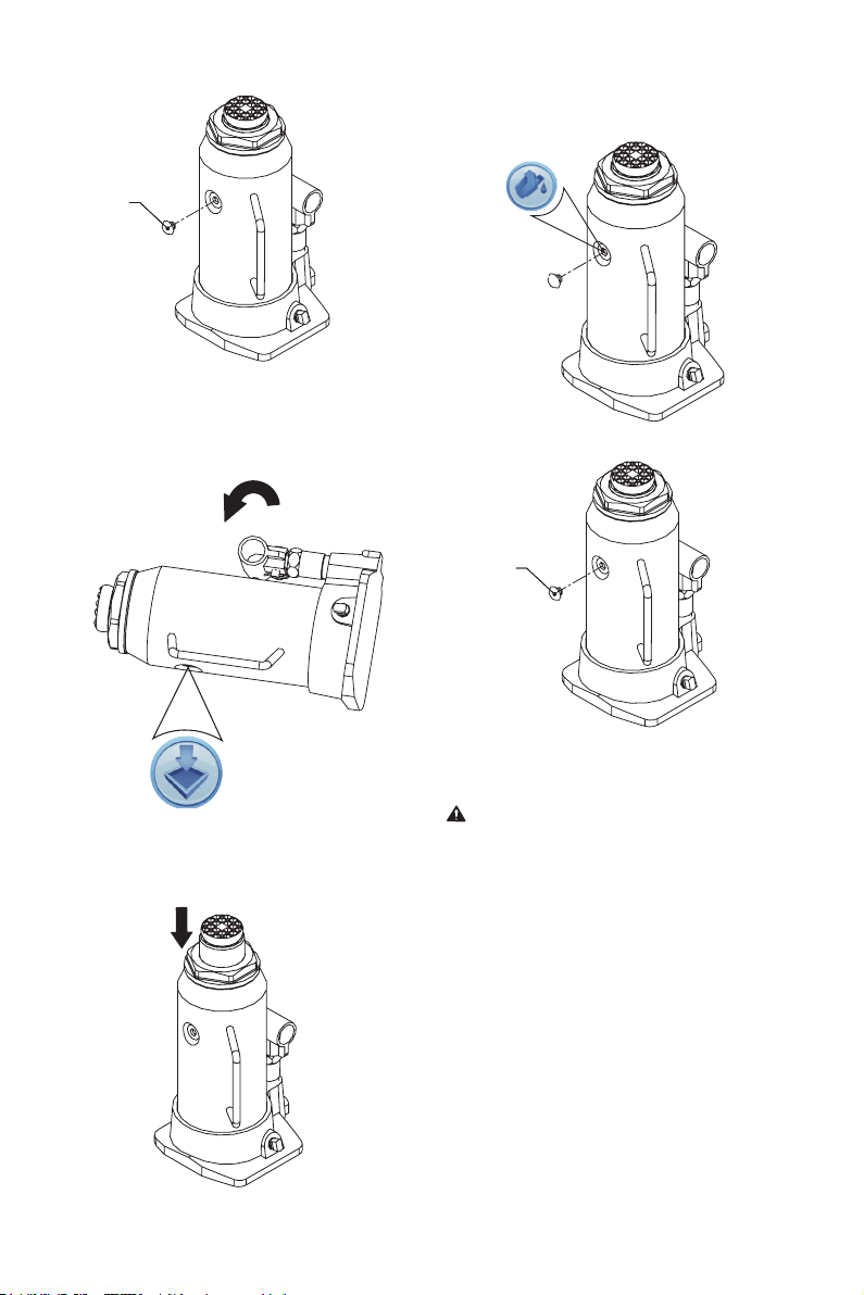
TO REPLACE JACK OIL
1. Position the jack on level ground and lower the
saddle.
2. Open release valve by turning handle counter-
clockwise (4 full turns).
2. Remove the oil plug.
R5
R5
R22
R7
14
3. Remove the oil plug. 6. Fill the oil case until oil level is just beneath the
lower rim.
KEEP DIRT AND OTHER MATERIAL CLEAR
WHEN POURING.
7. Replace oil plug.
8. Perform the Air Purge Procedure.
• DO NOT USE MOTOR OIL IN THE JACK.
• ONLY USE ANTI-FOAMING JACK OIL.
• ALWAYS USE A GOOD GRADE HYDRAULIC
JACK OIL.
• DO NOT USE HYDRAULIC BRAKE FLUID,
ALCOHOL, GLYCERINE, DETERGENT, MOTOR
OIL OR DIRTY OIL.
• USE OF A NON-RECOMMENDED FLUID CAN
CAUSE DAMAGE TO A JACK.
• AVOID MIXING DIFFERENT TYPES OF FLUID
AND NEVER USE BRAKE FLUID, TURBINE
OIL, TRANSMISSION FLUID, MOTOR OIL OR
GLYCERIN. IMPROPER FLUID CAN CAUSE
PREMATURE FAILURE OF THE JACK AND THE
POTENTIAL FOR SUDDEN AND IMMEDIATE
LOSS OF LOAD.
• DISPOSE OF HYDRAULIC FLUID IN
ACCORDANCE WITH LOCAL REGULATIONS.
4. Turn the jack on its side so that old oil will drain
from the oil ll hole.
Note: Dispose of hydraulic uid in accordance
with local regulations.
5. Position the jack on level ground and keep saddle
in the lowered position.
ADDITIONAL WARNINGS:
R5
R5

15
LUBRICATION
TROUBLESHOOTING
A periodic coating of light lubricating oil to pivot points will help to ensure that pump pistons move freely.
Note: Never apply oil to the saddle. If saddle extension threads require lubrication; clean thread surfaces with
a clean, dry cloth, then apply a drop of bearing grease to the threads. Distribute as evenly as possible along
the threaded post.
JACK
WILL
NOT
LIFT
LOAD
JACK
WILL
NOT
HOLD
LOAD
JACK
WILL
NOT
LOWER
POOR
JACK
LIFTING
WILL NOT
LIFT TO
FULL
EXTENSION CAUSES AND SOLUTIONS
Release valve is not completely closed
(Turn handle clockwise).
Weight Capacity Exceeded.
Air is in the hydraulics.
Purge air from system.
Low oil level. Add oil as required.
Oil reservoir is overlled.
Drain excessive oil.
Lubricate moving parts.
Jack is binding or foreign obstruction
Power unit malfunctioning.
Replace the power unit.
X XX
X
X X
X X XX
X X X
X
X
Safe Operating Temperature is between 40°F – 105°F (4°C - 41°C)

16
ASSEMBLY DIAGRAM
Optional

17
No. Part Description Qty
1 Bolt M12×25mm 8
2 Upper bolster 1
3 Washer 12 8
4 Spring washer 12 8
5 Nuts M12 8
6 TQ20002-36 Return spring 2
7 T91204 Bottle Jack 1
8 T51201-05 Hook 2
9Jack base 1
10 Nut M6 2
11 Lower bolster 1
12 T51201-02 Bolster plate 2
13 T51201-03 Support pin 2
14 Posts 2
15 Hex head bolt M10×30mm 4
16 Base 2
17 Washer M10 4
18 Spring washer M10 4
19 Nuts M10 4
20 T91203-31(ASM) Handle assembly 1
21 GB308-Φ6 Steel ball bearing Φ6mm 1
22 T90403-25(ASM) Release value assembly 1
23 TF1201C-29 Oil plug 1
24 Bottom crossbeam 1
25 T51201.5 Guide pilliars 1
26 T51201.MF Seal kit 1
ASSEMBLY PARTS LIST

18
WARRANTY NOTICE
WARRANTY INFORMATION
This equipment is covered under a 1-year limited warranty when used as recommended. Only those
items listed with a Part # are available for purchase. For assistance with the operation or the availability of
replacement parts, contact our Parts and Warranty Department at 1-888-44-TORIN (1-888-448-6746). Please
have available a copy of your receipt, the model number of the product, serial number, and specic details
regarding your question.
Not all equipment components are available for replacement; illustrations provided are a convenient reference
of location and position in the assembly sequence.
The manufacturer reserves the rights to make design changes and or improvements to product lines
and manuals without notice.
We want to know If you have any concerns with our products. If so, please call toll-free for Immediate
assistance. For additional web customer support help inquiries visit the Customer Service section at:
http://www.torin-usa.com.

19
TORIN ONE YEAR LIMITED WARRANTY
Torin Inc.® has been producing quality automotive repair and maintenance products since 1968. All products
sold are felt to be of the highest quality and are covered by the following warranty:
With proof of purchase for a period of one year from the date of that purchase, the manufacturer will repair or
replace, at its discretion, without charge, any of its products or parts thereof which fail due to a defect in
material or workmanship. This warranty does not cover damage or defects caused by improper use, careless
use or abuse of the equipment. This warranty does not cover parts normally considered to wear out or be
consumed in the normal operation of the equipment. Except where such limitations and exclusions are
specically prohibited by applicable law, (1) the CONSUMERS SOLE AND EXCLUSIVE REMEDY SHALL BE
THE REPAIR OR REPLACEMENT OF DEFECTIVE PRODUCTS AS DESCRIBED
ABOVE, and (2) THE MANUFACTURER SHALL NOT BE LIABLE FOR ANY CONSEQUENTIAL OR
INCIDENTAL DAMAGE OR LOSS WHATSOEVER, and (3) THE DURATION OF ANY AND ALL
EXPRESSED AND IMPLIED WARRANTIES, INCLUDING, WITHOUT LIMITATION, ANY WARRANTIES OF
MERCHANTABILITY AND FITNESS FOR A PARTICULAR PURPOSE, IS LIMITED TO A PERIOD OF ONE
YEAR FROM DATE OF PURCHASE. Product alteration in any manner by anyone other than us, with the sole
exception of alterations made pursuant to product instructions and in a workman like manner. You
acknowledge and agree that any use of the product for any purpose other than the specied use(s) stated in
the product instructions is at Your own risk.
Always check for damaged or worn out parts before using any product. Broken parts will affect the equipment
operation. Replace or repair damaged or worn parts immediately. Do not modify the product in any way.
Unauthorized modication may impair the function and/or safety and could affect the life of the equipment.
There are specic applications for which products are designed and tested during production. Manufacturer
provided warranted items are not authorized to be repaired by anyone other than the manufacturer or
manufacture approved repair person. Distributor does not have authorization to amend these statements. You
acknowledge and agree that any modication of the product for any purpose other than manufacturer
completed repairs is at your own risk. Before using this product, read the owner's manual completely and
familiarize yourself thoroughly with the product and the hazards associated with its improper use.
IMPORTANT: BEFORE FIRST USE on any Lift verify that a daily inspection has been completed and that all
components are in the proper working order.
This limited warranty gives you specic legal rights, and you also may have other rights, which vary from
state to state. Some states do not allow limitations or exclusions on implied warranties or incidental or
consequential damages, so the above limitations may not apply to You. This limited warranty is governed by
the laws of the State of California, without regard to rules pertaining to conicts of law. The state courts
located in San Bernardino County, California shall have exclusive jurisdiction for any disputes relating to this
warranty.
Manufacturer reserves the rights to make design changes and or improvements to this product lines and
manual without notice. We at Torin have taken every effort to ensure complete and accurate instructions have
been included in this manual. However, possible product updates, revisions and or changes may have
occurred since this printing. Torin Inc. reserves the right to change specications without incurring any
obligation for equipment previously or subsequently sold. Not responsible for typographical errors.
Alternately Customer Service can be reached through www.torin-usa.com or via email at
Not all equipment components are available for replacement, but are illustrated as a convenient reference of
location and position in the assembly sequence. Contact Customer Service for equivalent component. When
you contact us, please have your Product’s Model number, Serial Number and Description ready so that we
may help you efciently. This information can be found on a sticker on the product.
For any warranty support or if your Torin® equipment is not functioning properly contact
Torin® Customer Service directly by telephone at 1-888-44-TORIN (1-888-448-6746)
8:00am – 5:00pm Pacic Time, Monday – Friday
www.torin-usa.com Made in China

MANUEL DU PROPRIÉTAIRE
PRESSE D’ATELIER - 12 TONNES
Article No. T51201
Questions, problèmes, pièces manquantes? Avant de retourner voir votre fournisseur, appelez notre service à
la clientèle au 1-888-44-TORIN (1-888-448-6746) entre 8 heures et 17 heures, HNP, du lundi au vendredi.
Lisez attentivement et comprenez toutes les DIRECTIVES DE MONTAGE ET DE FONCTIONNEMENT avant
l’utilisation. Vous pouvez subir des blessures graves si vous ne vous conformez pas à ces règles et autres
précautions de sécurité.
AVERTISSEMENT!
Table of contents
Languages:
Other Torin BIG RED Power Tools manuals

Popular Power Tools manuals by other brands

Terex
Terex TS14G Maintenance manual

Nitto Kohki
Nitto Kohki delvo DLV45C Series instruction manual

Milescraft
Milescraft WorkCenter 1098 quick start guide

Titgemeyer
Titgemeyer TIOS 220 operating manual

Jefferson Professional Tools & Equipment
Jefferson Professional Tools & Equipment JEFPDB0750-12S user manual

Schmidt
Schmidt 3 Operator's manual


